Note: Descriptions are shown in the official language in which they were submitted.
CA 02152282 2001-06-26
2~5~282
PCIiL~'93/1~~1
-1-
FAST RESPONSE WELD HEAD
Field of the Invention
The present invention relates to a device for resistance welding, and more
particularly
to a fast-response weld head having servo control for sensing and controlling
the speed.
direction, force and duration of the weld or bonding head.
Background of the Invention
In resistance welding, heat and pressure are used to fuse metals together.
Heat
generated by the resistance of the work pieces to the flow of electricity
either melts the
material at the interface, or at least reduces its strength to a level where
the surfaces of the
materials become plastic. When the flow of current stops, the electrode force
is maintained,
for a fraction of a second, while the weld rapidly cools and solidifies.
Broadly speaking, there are several parameters which can be controlled in the
resistance
welding process, these being the electrode force on the workpiece, the
magnitude of the weld
current, and the duration of the weld current. These parameters have different
optimum
values for different materials being welded. If these parameters are not
closely controlled.
the welds obtained can vary in quality.
Maintaining weld quality in integrated circuit packages and micro-circuit
components
and assemblies is particularly important. Precision welding equipment is used
for the welding
of these extremely small items. The weld heads for most prior an precision
welding
equipment are driven manually or pneumatically through a spring nest. Because
of the
limitations in control of these types of systems, a number of desirable
control features are
either very difficult or impossible to obtain.
AMENDED SHEET
CA 02152282 2001-06-26
-2-
With such prior art welding equipment there is no practical way to program in
different speeds, forces or positions. Also, there is no satisfactory way to
achieve the
desired speed of response of the weld head to the onset of welding current or
to prevent
the force from continuing to increase after the weld has been completed, which
can cause
damage to the weld or the entire component.
Not only is there a problem with not being able to control the force with
prior art
welding equipment, additionally, there is no means for automatically
controlling the
speed and the duration of contact of the weld or bonding head and for varying
the amount
of force during contact. Therefore, there exists a need for the automatic
control of speed,
response time, force, duration and pressure of the weld head in a precision
welding
device for the welding of a broad range of precision applications such as
integrated
circuit packages and micro circuit components.
Summary of the Invention
This invention provides an apparatus and method for precisely controlling
welding parameters essential for optimum welding. The present invention is
readily
controlled by computer-generated signals for use with automated equipment or
by a
microprocessor.
Accordingly, the present invention provides a method if rapid precision
welding
of an object comprising the steps of:
(a) providing a movable electrode;
(b) moving the electrode into contact with the object using a fast response
weld head on which the electrode is mounted;
(c) increasing the force exerted by the electrode to a first predetermined
level;
(d) applying electrical welding energy through the electrode to the object for
a
predetermined duration of time;
(e) holding the force exerrted at said first level for a first length of time
as the
object softens;
(f) increasing the force exerted to a second predetermined level for a second
shorter length of time; and
CA 02152282 2001-06-26
-2a-
(g) returning the electrode force to said first predetermined level during the
remaining portion of the interval of application of weld energy wherein the
electrode
maintains contact with the object at all times during welding eliminating
expulsion of
material.
The present invention also provides in a fast response weld head, control
means
comprising:
means for selecting a force to be applied by an electrode on an object to
enable
low impact contact;
means for varying the speed of movement of the electrode relative to the
object;
means, comprising a linear magnetic actuator, for varying the level of force
exerted by the electrode on the object; and
means for increasing the force exerted by the electrode on the object at a
predetermined rate prior to the start of weld energy wherein control of the
speed of the
electrode enables low impact contact with the object minimizing movement of
and
damage to the object.
The present invention also provides a method of rapid precision welding of an
object by an electrode with user-controlled parameters comprising:
(a) providing a movable electrode;
(b) generating a speed control signal defining a rate of motion of the
electrode;
(c) generating a predetermined force control signal defining a first force to
be
applied to the object by the electrode;
(d) generating a position control signal defining a displacement of the
electrode relative to the object;
(e) generating a duration control signal defining a length of time the
electrode
contacts the object;
(fj driving the electrode toward and into contact with the object;
(g) rapidly increasing the force applied by the electrode after contact;
(h) applying welding energy to the object through the electrode for a
predetermined interval;
CA 02152282 2001-06-26
-2b-
(i) generating a transient force greater than said first force for a brief
interval
during the weld energy interval and prior to the end of the time interval when
the
electrode contacts the object; and
(j) rapidly decreasing the force applied by the electrode after the weld
energy
interval to minimize the overall time interval of each welding operation.
In a further aspect, the present invention provides in a fast response weld
head,
force controlling means comprising:
means for programming a prescribed force control signal representative of a
force
to be applied by an electrode on an object; and
means, comprising an open loop control circuit, for programming a transient
force
applied by the electrode to the object; and
means for maintaining the prescribed force and transient force exerted by the
electrode on the object for predetermined intervals.
The present invention also provides a fast response weld head comprising:
a support means;
means for mounting a movable shaft on the support means permitting motion of
the shaft relative tot he support means;
driving means, comprising a linear magnetic actuator, for moving the shaft
linearly with respect to the support means;
operator controlled mans for controlling a force to be exerted by the weld
head;
means for maintaining the operator controlled force between the electrode and
the
workpiece for a predetermined duration; and
means for applying a transient amount of force during the force maintaining
interval.
The present invention also provides a fast response weld head comprising:
a servo control means for controlling position of an electrode relative to an
object;
detecting means coupled to the servo control means for detecting electrode
contact with the obj ect;
open loop control means for controlling the force exerted by the electrode in
response to a current; and
CA 02152282 2001-06-26
-ZC-
control switching means coupled to the detecting means for changing control of
the electrode from the servo control means to the open loop control means upon
detection
of electrode contact with the object.
The apparatus and method controls the speed, position, force and the rate of
force
of contact of the welding electrodes with the workpiece, as well as the
duration of the
weld current. Furthermore, the invention provides a method for applying and
controlling
different user-defined forces for predetermined durations of time before,
during and after
a weld current is enabled to the electrode.
These highly desirable features are incorporated into a mechanical weld head
driven by a control system containing a position servo loop. The loop,
controlled by
user-defined input voltages, comprises an input resistor, a feedback resistor,
a servo
amplifier, a magnetic linear actuator, and a position transducer. The actuator
is attached
to the welding electrode through a linear output shaft which can be driven
toward and
away from a workpiece. The linear motion of the output shaft is coupled to a
position
transducer, allowing for precise position measurements. Moreover, speed can be
controlled because the rate the shaft moves is directly proportional to the
rate of change
of the input voltage to the loop. Therefore, the output shaft, and hence the
welding
electrode, can be positioned anywhere in its operating span at any speed
within the
capability of the linear actuator.
The speed and position control features allow for fast, precise welding. Once
the
command is given to begin a weld cycle, the welding electrode can be driven
rapidly to a
search position thousandths of an inch above the maximum height of the
workpiece.
Then the speed of the output shaft can be significantly reduced as the
electrode contacts
the
WO 94/14564 ~ ~ ~ PCT/US93/12412
-3-
workpiece to prevent damage to especially fragile workpieces and to prevent
dislodging of
the piece part in the welding fixture due to shock.
The three control feature of this invention is provided by the magnetic linear
actuator.
The output shaft of this actuator is attached to the welding electrode,
allowing the electrode
to he driven by the shaft. As the shaft and electrcule are driven toward a
workpiece, the
electrode will first contact the rigid workpiece and begin to apply force up
to a first
predetermined amount. The shaft stops momentarily, then accelerates rapidly
during the
interval when the weld current is tired, causing additional mechanical force
to he exerted on
the workpiece tier a preselected amount of time during the weld current
interval, returning
prior to the termination of the weld current to the first lesser predetermined
amount of force.
A linear magnetic actuator of the type described in U.S. 3,889,139 is suitable
for use
in the apparatus according to the present invention. Other examples include
3,505,544;
3,666,977 and 3,576,454.
In order to maintain a desired force for unitbrm welding of several similar
workpieces,
the actuator is controlled or programmed to exert different forces on the
workpiece before,
during and after the interval when weld current is actually t7owing. In a
typical welding
sequence, the electrode contacts the workpiece, increases the force to a first
level and holds
that force for a predetermined interval before an additional transient force
is exerted. When
the forces reaches the first level, welding energy is applied tbr a programmed
interval.
Before the transient force is exerted, the input current to the actuator is
held constant,
maintaining the position of the output shaft as well as the force applied by
the electrode on
the workpiece. In some instances there may he a tiring delay before weld
current is supplied
to the welding electrode. This feature is desirable to allow any mechanical
vibration of the
weld head to diminish before the actual weld energy is applied.
When the user-defined weld current is delivered to the electrode, the
workpiece softens
and the preprogrammed additional transient amount of force is applied by the
electrodes to
the workpiece. Prior to the termination of the weld current, the force is
reduced and
continues at the lower force level as the weld cools. This weld current starts
after welding
electrode force is applied and stops before the electrode force is removed.
Finally, the
electrode is raised on cue from the control system. A precise, repeatable weld
has been
performed.
As can be readily inferred from this summary, the features of this invention
allow for
precision control of critical welding parameters not achievable in prior art
welding systems.
These features are extremely important for the optimum welding of small to
large workpieces
starting from small, fragile components and chips to and including automotive
body welding
applications..
WO 94/14564 PCT/US93/12412
x
Brief Descripticm of the Drawin;,S
'The invention will now be described in more detail with reference to the
accompanying
drawings in which:
FIG. 1 is a side elevation showing a motorized embodiment of a fast response
weld
head apparatus according to the present invention;
FIG. 2 is a block diagram of the control system tbr the weld head apparatus of
FIG.
l;
FIG. 3 is a timing diagram for the weld head apparatus shown in FIG. 1 showing
the
actions and timing intervals of the various operations of the apparatus during
a typical weld
cycle;
FIG. 4 is a side elevation showing the motorized weld head apparatus along
with user
controls for the weld head;
FIG. 5 is a side elevation showing a presently preferred embodiment of a fast
response
weld head apparatus utilizing a linear actuator according to the present
invention;
F1G. 6 is a block diagram of the control system for the weld head apparatus of
FIG.
5; and
FIG. 7 is a timing diagram for the weld head apparatus shown in FIG. 5 showing
the
actions and timing intervals of the various operations of the apparatus during
a typical weld
cycle.
WO 94!14564 PCT/US93/12412
-5-
Detailed Description of the Invention
A motorized weld head apparatus according to the present invention
incorporates
control apparatus which enable a user to control critical parameters of a weld
cycle via servo
controlled motion. In FIG. I, a presently preferred embodiment of the suh_ject
weld head
apparatus provides a welding electrode to he moved upwardly and downwardly to
precise
locations along the z-axis of the electrode at a variable speed. As a result
of position and
speed control, both the rate of force and the amount of terse the electrode
exerts on a
workpiece can be varied and controlled as required for optimum welding.
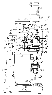
The various components of the motorized weld head 2 will tirst be described.
Referring to FIG. 1, a support tbr the weld head comprises a two-legged base 3
to which
housing 4 is t7xedly mounted. Housing support members including an upper
member 6, a
middle member 8 and a lower member 10 each extend horizontally across the
length of the
housing. The three support members together define an upper cavity 12 and a
lower cavity
14. Housing 4 supports a drive motor 16 which moves a welding apparatus. The
welding
apparatus, to be discussed subsequently, includes a welding electrode 38 and
an electrode
holder 40. Weld apparatus controls including a keyboard 54 and a trot pedal 56
shown in
FIG. 4, are connected to circuit board 42 through cables 58. The circuit hoard
containing
the amplifier for the control system, fixedly attaches to supports in the
lower cavity of the
housing. The remaining elements of the control system, to he discussed
subsequently, are
housed external to the weld head in, tier example, the keyboard controls 54
(FIG. 4) or an
external power supply (not shown). Transducer apparatus 48,50, for measuring
both the
applied force exerted on a workpiece 46 by the welding electrode and the
position of the
electrode relative to the workpiece, is also mounted on housing 4.
The drive for the welding apparatus comprises a hidirectional DC servo motor
16, a
gearcase 18, a motor driven lead screw 20 threaded into a lead nut 28, and an
output shaft
36. Motor 16 and gearcase 18 are t7xedly mounted cm top of upper support
member 6. To
enable the motor to rotate the lead screw, the upper end of lead screw 20 is
attached to the
gearcase through an internally threaded universal coupling 22. Both the
universal coupling
and the lead screw are supported by a thrust hearing 26 fixedly mounted on the
upper surface
of the middle support member 8 by clamp 52. The thrust hearing protrudes
through the
middle support member and prevents linear motion of the lead screw as it
threads into lead
nut 28 within the lower cavity.
To facilitate the conversion from the angular mcnion of the lead screw 20 to
the linear
motion of the lead nut 28 along the screw, one end of an antirotation clamp 30
fixedly
attaches to the lead nut to prevent angular motion of the nut. The other end
of the
antirotation clamp is movably mounted to an antirotation shaft 32 by means of
bearings 34.
The antirotation shaft 32, fixedly mounted to honh the middle support member 8
and the
WO 94/14564 ~ ~ ~ ~ PCT/US93/12412
-6-
lower support member 10, vertically traverses the lower cavity in parallel
alignment to the
z-axis of the driving apparatus. As the lead nut is displaced by the angular
motion of the lead
screw driven by the motor, the antirotation clamp slides vertically along the
length of the
antirotation shaft in conjunction with the displacement of the nut. Thus,
angular displacement
of lead nut is prevented while~linear displacement is allowed.
Located beneath the lead nut and antirotation clamp, output shaft 36 protrudes
throubh
the lower support member 10 and provides a mechanical connection between the
drive portion
and the welding portion of the weld head apparatus. As the lead nut is
displaced, shaft
bearings (not shown) within the lower support member 10 allow linear motion of
the output
shaft. The welding portion, comprising an electrode 38 secured by an electrode
holder 40,
is attached to the output shaft through a compressible spring assembly 44. As
the motor 16
drives the welding apparatus downward on cue from the control system the
electrode contacts
a rigid workpiece 46 on work table 47. The workpiece exerts an upward z-axis
force on the
spring assembly 44 resulting in its compression. The rigid output shaft,
however, continues
its downward motion, further compressing the spring assembly 44 along the
downward z-axis.
The net effect of the combined force from the drive motor and the workpiece is
a linear force
on the spring assembly proportional to the tordue provided by the motor.
To measure the force exerted on the workpiere by the welding apparatus, a load
cell
48 or other pressure transducer is mounted between the output shaft and the
spring assembly.
The load cell accurately measures the tbrce exerted on the workpiece by the
welding electrode
38 and generates a voltage output signal proportional to the three which is
amplified an the
printed circuit board 42 and transmitted to the control system. To measure the
linear
displacement of the welding apparatus along the z-axis, a position transducer
50 contains a
cylindrical shaft 43 that moves linearly within a slightly wider cylindrical
transducer body 45
mounted to the middle support member 8 via the transducer clamp 52. A
compression spring
41, coaxially mounted around the transducer shaft, keeps the shaft extended to
its outward
stop. The spring compresses as the antirotation clamp 30 moves upward, keeping
the end of
the position transducer shaft against the antirotation clamp.
Although one form of motorized weld machinery has been described, it is
contemplated
that other types of motorized weld heads may he used in conjunction with the
servo control
system.
A control system for operating the mechanical motorized weld head apparatus
which
allows the user direct control of critical welding parameters will now be
described.
A block diagram for explaining the control system is shown in FIG. 2. The user
control means 60 allows the user to command the operaticm of the weld head
either directly,
with control apparatus such as a keyboard with a display 54 and a toot pedal
56 (FIG. 4) or
automatically, with a computer program. Regardless of the means used. the
speed, ford,
WO 94/14564 PCT/US93/12412
_7_
duration, and position of the welding apparatus may effectively he controlled.
The user
controls drive generator 62 to produce a voltage waveti~rm whose shape and
amplitude is
dependant on the control desired. Fur example, as the generator receives a
command from
the user control to increase the speed of the welding apparatus hetween
desired positions. the
generator will produce a proportionally increased voltage ramp signal. This
voltage ramp
produced by the generator is one component of the input voltage to the servo
loop circuit.
The servo loop circuit, an essential feature of this control system, comprises
input
resistor 64, servo amplitier 66, hidirectiunal DC servo motor 16, linear
motion position
transducer 50, and feedback resistor 70. As the input voltage enters the servo
loop, it first
encounters servo amplifier 66 which augments the voltage signal in order to
sufticiently
power the motor. The voltage delivered to the servo motor is proportional to
the voltage
input from the generator 62. The more voltage delivered to the motor, the
taster it will run.
By means of the angular to linear nu>tiun conversion apparatus the motor can
drive the
welding apparatus upwardly and downwardly along the z-axis. The position
transducer,
independently powered by transducer driving circuitry 68, precisely measures
the
displacement of the welding apparatus and outputs a voltage signal
proportional to the said
displacement directly into the feedhac:k loop comprising the feedhack
resistor. The feedback
voltage signal provides a second component of input voltage to the servo
amplifier in addition
to that produced by the generator. The effect of the feedhac;k loop is that a
instantaneous
preferred steady state position of the welding apparatus will he maintained by
the servo loop.
If the position transducer senses that the welding apparatus is displaced from
its instantaneous
steady state position, the fundamental operation of the servo loop will drive
the apparatus
back toward the correct position.
As the welding apparatus is driven downwardly by the motor, it may engage a
rigid
workpiece 46. A force transducer, comprising the load cell 48, is
independently powered by
transducer driving circuitry 72. The load cell senses the ti~rve exerted on
the workpiece and
more particularly, on the spring assemhly 44, by the welding apparatus and
outputs a voltage
signal proportional to the amount of force exerted on the workpiece into a
force amplifier 74.
The resulting augmented voltage signal from the furi:e amplitier provides one
of two inputs
into a force comparator 76. The second input is providad by a force program
78. The
function of the comparator is to continuously compare the two inputs and
change state when
the inputs are equal.
The force program, as well as the entire means for sensing force in
comhination with
the servo loop, is an important feature of the control system. The tierce
program is a
preprogrammed or user controlled means of producing a voltage level which
represents the
optimum force to he applied by the welding apparatus on to the workpiece. The
force
program can be programmed either for simple constant three welding
applications or, it'
WO 94/14564 PCT/US93/12412
_g_
necessary, for more complex variable force applications. When the force sensed
by the
load cell and thus its output voltage equals the output voltage of the tone
program, the
comparator will change state triggering two separate but simultaneous voltage
signals. The ,
first signal triggered is a hold signal 80 to the generator 62 which commands
the generator
to maintain the present input voltage tc> the servo loop. The functicm of the
hold signal is to
maintain the force specified by the force program between the welding
apparatus and the
workpiece. The hold signal can he manipulated either by the user or by a
computer program
to maintain the duration of the force as desired. The second signal triggered
by the
comparator is a firing delay 82 which temporarily blocks current tlow to the
welding
electrode via a switch (not shown) within the weld current control circuit.
The purpose of
the tiring delay is to allow mechanical vibrations of the welding apparatus to
signit7cantly
diminish prior to enablement of a weld current to the electrode. The tiring
delay further
allows the user to visually c:he~k tha ali5nment of the welding apparatus with
respect to the
workpiece, vary the force exerted on the workpiece by the welding electrode,
or compute an
appropriate welding current. As with the hold signal, the length of the firing
delay can be
freely altered by the user or a computer program.
The end of the firing delay triggers a weld fire signal 84 which enables the
welding
current to flow through the weld current control circuit to the electrode for
actual welding.
This signal, also programmable or user-controlled, may be long or short
depending on the
requirements of the weld to the workpiece. The end of the weld tire signal
which cuts off
user control to the generator 62 by means of switches 86,88. Finally, under
direct control
of the servo loop, the welding apparatus rises away from the welded workpiece
marking the
end of a weld cycle.
In order to further describe the essential features of the motorized weld
head, an
example of a typical weld cycle will now he described by reference to the
timing diagram of
FIG. 3.
During a typical weld cycle, at initial time to, the user will place the
workpiece 46 to
be welded directly underneath the upper electrode 38. At this time the welding
apparatus will
be positioned at an upstop position 100, a predetermined position representing
the minimum
displacement of the driving shaft along the z-axis relative to the DC motor.
At time tl, by
depressing a weld cycle start switch 88 such as a toot pedal to change the
state of the switch
112, the user, via the control system, will drive the welding electrode 38
downwardly from
the upstop position to a search position 102 slightly (e.g., three thousandths
of an inch) above
the maximum height of the workpiece 46.
At time t2, by depressing a search position descent switch 86 such as a second
level
of the tbot pedal, the switch will change state 1 14. The welding electrode
will proceed
downwardly (indicated by path I ) from the search position toward the
workpiece. At time
WO 94/14564 PCT/1JS93/12412
-9-
t3, assuming the workpiece is aligned axially with respect to the electrode
38, the electrode
will engage the workpiece. Due to the rigidity of the workpiece, the electrode
will cease to
move further downward. However, the driven output shaft 36 will continue to
proceed
downwardly (indicated by path 2) he>th compressing the spring assembly between
the shaft
and the electrode and increasing the force exerted on the workpiece by the
electrode. Also
at t3, when the load cell 48 senses the.electrode fore 110 via the compression
of the spring
assembly 44, the load cell wilt output a voltage signal into the force
comparator 76.
At time t4, the electrode force 110 sensed by the load cell equals that of the
force
program 78. The comparator changes state 116 triggering both the hold delay 22
and the
tiring delay 118. The hold delay maintains the constant force specified in the
t«rce program
between the electrode and the workpiece. At time t5, after any mechanical
vibration of the
electrode has adequately diminished, the firing delay I 18 switches off.
Simultaneously the
weld signal 120 switches on, enabling current flow to the electrode tip. At
time t6, the weld
signal ends and the current is stopped. However, the hold signal continues to
maintain a
constant applied force to the workpiece as the molten metal cools. At time t8
the hold signal
ends, the force comparison ceases, and the electrode rises releasing the force
applied to the
workpiece. At time t9, the welding apparatus automatically returns to the
upstop position
under direct control of the servo loop. Finally, by time t10, all switches
have returned to
their initial positions, marking the end of the weld cycle.
If no wurkpiece is encountered by the electrode, the output shaft and the
electrode wilt
travel to a predetermined downstop position 106 at time t7 (indicated by path
3). This
downstop position represents a predetermined displacement point of the driving
shaft relative
to the motor along the downward z-axis. Since no force is built up to initiate
the completion
of the cycle, the electrode will remain at the downstop position until the
weld cycle switch
88 changes state 114 ending the weld cycle. Thus, the control system provides
means to
precisely control welding parameters.
In another and presently preferred embodiment of the invention, a fast
response weld
head apparatus according to the present invention incorporates a linear
actuator which enables
a user to control critical parameters of a weld cycle. In FIG. 5, a presently
preferred
embodiment of the subject weld head apparatus provides a welding electrode to
be moved
upwardly and downwardly to precise locations along the z-axis of the electrode
at a variable
speed under control of a linear actuator. As a result of microprocessor
control, both the rate
of force and the amount of force the electrode exerts on a workpiece can he
varied and
controlled as required for optimum welding.
The various components of the weld head 130 will first he described. Referring
to
FIG. 5, a support for the weld hand comprises a hale 132 cm which a housing
134 is fixedly
mounted by means of a spacer block 133. Housing 134 supports a linear magnetic
actuator
WO 94/14564 PCT/US93/12412
~~:v~28~
-l o-
136 which moves a welding apparatus 137. The welding apparatus includes a
welding
electrode 138 and an electrode holder 140. Weld apparatus controls including a
keyboard and
a foot pedal are utilized similar to those shown in FIG. 4, and are connected
to multipin .
connector 142. A position transducer 144, for measuring the position of the
electrode relative
to the workpiece, is also mounted on housing 134.
A non-rotatable output shaft 148 extends from beneath actuator 136 and
provides a
mechanical connection between the actuator drive and the welding portion of
the weld head
apparatus. As the shaft is displaced, shaft hearings (not shown) allow linear
motion of output
shaft 148. The welding portion, comprising electrode 138 secured by electrode
holder 140,
is attached to the output shaft 148. As the actuator 136 drives the welding
apparatus
downward on cue from the control system the electrode contacts a rigid
workpiece 156 on
work table 158. The electrode exerts a downward z-axis force on the workpiece.
In contrast with the motorized weld head embodiment the path of the driven
shaft anti
the electrode shaft are the same. In this embodiment the spring compliance in
the weld shaft
is replaced with a programmable transient force. The follow-up spring has been
eliminated
and the force required to keep constant pressure on the softened workpiece is
supplied by a
short pulse of force, that accelerates the relatively large mass of the weld
head in a short
time.
An important characteristic feature of a linear magnetic actuator is its
linear force
response to an increase or decrease in current supplied to the actuator which
means direct
control of the force exerted by control of the current supplied to the
actuator and by provision
of predetermined current profiles for the actuator. This enables control of
electrode velocity
prior to the welding operation and control of the electrode force during the
welding operation.
Control of electrode velocity enables the obtaining of a low impact by the
electrode when it
contacts the workpiece thereby preventing damage to the workpiece and
eliminating
movement of the workpiece in the welding fixture. Control of electrical force
enables
increasing or ramping up the three applied by the electrode at a controlled
rate to control the
seating of workpieces relative to one another for improved weld duality. Since
electrode
force is determined electronically, predetermined three values and three
profiles can be stored
by a microprocessor as part of the overall weld schedules. This means that the
desired force
profiles can automatically be selected whenever a different weld schedule is
selected.
As indicated, a characteristic of a linear magnetic actuator is its rapid
response time.
A rapid increase in applied force can he obtained in extremely short intervals
of I to 3
milliseconds by increasing the current to the actuator which in turn causes
rapid acceleration
of the electrode so that it maintains contact with the workpiece as it becomes
plastic: or molten
during the welding operation. Control of electrode contact with the workpieces
eliminates
WO 94/14564 PCT/US93/12412
.. '
_11_
the tendency to cause molten or plastic; portions of the workpiece to he
expelled from the
weld site.
Other advantages of the present invention are increased efticiency and speed
of
operation. With a magnetic linear actuator, the time reduired to ramp up m and
down from
a desired force is reduced in comparison to prior art welders. In welding
applications
requiring many repetitive welds on the same workpiece, this fast response of a
linear actuator
and the weld head provides increased production rates and savings in time and
expense by
enabling quicker setups and welds and more welds per unit time.
1n operation the weld electrode moves to the search position, and then to the
level of
the workpiece. As contact is made with the workpiece, the electrode force
signal, from the
microprocessor 159, is ramped up at a programmed rate until the programmed
force is
reached. Since the magnetic actuator has a very linear current vs. output
force curve, the
force is no longer monitored by a transducer. The ma~~neti~ actuator is
pru~~ramm~cl with the
correct current profile to produce the desired terse protile. Upon reaching
the programmed
force, a weld signal is sent to the welding power supply and weld current is
supplied to the
weld electrode and workpiece. A slight delay of 1 to 10 milliseconds is
programmed in to
allow the workpiece time to soften (transient tierce delay) and then the
transient force is
produced for ,just enough time to accelerate the mass of the electrode
mechanism to follow
the collapse of the weld.
The force exerted by the weld electrode is then returned to normal tier the
remainder
of the weld, which cools rapidly as the weld current decreases. Atter the hold
duration
expires, weld force is removed, and the electrode returns to an upstop
position in preparation
for the next weld. The next weld can only begin after switches 186 and 188 are
released and
reactuated.
A control system fur operatinb tha linear magnetic actuator weld head
apparatus which
allows the user direct control of critical welding parameters will now be
described.
A block diagram illustrating the control system is shown in FIG. 6. The user
control
means allows the user to command the operation of the weld head either
directly. with control
apparatus such as a keyboard with a display and a foot pedal ur automatically,
with a
computer program. Regardless of the means used, the speed, fore, duration, and
position
of the welding apparatus may effectively he controlled. A microprocessor 1~9
controls the
electrode force signal. For example. as the generator receives a command from
the user
control to increase the speed of the welding apparatus between desired
positions, the generator
will produce a proportionally increased voltage ramp signal. This voltage ramp
produced by
the generator is one component of the input voltage to the servo loop circuit.
The servo loop circuit, an essential feature of this control system, comprises
a position
digital to analog converter 16~, a ti>rce digital to analog u~nverter 157,
input resistor 160,
WO 94/14564 PCT/US93I12412
servo amplifier 162, linear magnetic actuator 164, linear motion position
transducer 166, and
feedback resistor 168. As the input voltage enters the servo loop, it first
encounters servo
amplifier 162 which augments the voltage signal in order to sufficiently power
the actuator
164. The voltage delivered to the actuator is controlled by microprocessor
159. The actuator
drives the welding apparatus upwardly and downwardly along the z-axis. The
position
transducer 161, independently powered by transducer drivin~~ circuitry 170,
precisely
measures the displacement of the welding apparatus and outputs a voltage
signal proportional
to the said displacement directly into the feedback loop via feedback resistor
168. The
feedback voltage signal provides a second component of input voltage to the
servo amplifier
in addition to that produced by the microprocessor. The effect of the feedback
loop is that
a instantaneous preferred steady state position of the welding apparatus will
he maintained by
the servo loop. If the position transducer senses that the welding apparatus
is displaced from
its instantaneous steady state position, the fundamental operation of the
servo loop will drive
the apparatus hack toward the correct position.
The pUSltlOn transducer and associated circuitry in conjunction with the
actuator senses
the downstop position when the electrode contacts the workpiece. A change of
length in the
welding electrode automatically results in a new downstop position. Because of
the
programming and sensing capabilities of the linear magnetic actuator and
transducer, the
actuator will automatically react to stop a welding operation when the
electrode fails to begin
exerting a force at the expected location or prematurely experiences a contact
prior to the
expected location. In either event. the actuator aborts the welding operation
before
workpieces are harmed allowing an operator to investigate the cause of the
problem. The
force program, as well as the entire means for sensing force in combination
with the servo
loop, is an important feature of the control system. The tbrce program is a
preprogrammed
or user controlled means of producing a current level which represents the
optimum force to
be applied by the welding apparatus on to the workpiece. The force program can
be
programmed either for simple constant force welding applications or, if
necessary, for more
complex variable force applications. In order to further describe the
essential features
of the linear actuator weld head, an example of a typical weld cycle will now
be described
by reference to the timing diagram of FIG. 7.
During a typical weld cycle, at initial time t0, the user will place the
workpiece 156
to he welded directly underneath the weld electrode. At this time the welding
apparatus will
be positioned at an upstop position 200, a predetermined position representing
the minimum
displacement of the driving shaft along the z-axis relative to the linear
actuator. At time tl,
by depressing a weld cycle start switch to change the state of the switch 212,
the user, via
the control system, will drive the weldin~~ electrode 138 downwardly from the
upstop position
WO 94/14564 ~ PCT/US93/12412
-13-
to one of a selection of possible seare;h positions 202 slightly (e.g., three
thousandths of an
inch) above the maximum height of the workpiec:e 156.
At time t2, by depressing a search position descent switch 186 such as a
second level
of the foot pedal, the switch will change state 214. The welding electrode
will proceed
downwardly (indicated by path 1 ) from the search position toward the
workpie~e. At time
t3, assuming the workpiece is aligned axially with respect to the electrode
138, the electrode
will engage the workpiece. Due to the rigidity of the workpiece, the electrode
will cease to
move further downward. At t3, the electrode force rate begins to increase and
reaches the
programmed fore at t4.
At time t4 the weld signal 216 is applied and the onset of the torte hold
duration 218
begins. The programmed transient terse delay 220 also is initiated and extends
to t5. At t5
the transient torte increase is applied for a short duration of 1 to 10
milliseconds until t6
when the transient force is terminated. The electrode tierce then returns to
normal until t7
when the electrode is raised again to the upstop position.
The described embodiment of the invention is only considered to be preferred
and
illustrative of the inventive concept; the scope of the invention is not to be
restricted to such
embodiment. Various and numerous other arrangements may he devised by one
skilled in
the art. For example, all of the user controls could take the ti~rm of a
computer program,
capable of producing numerous and complex welding operations automatically. An
analog
current can also be utilized to provide control signals in lieu of a
microprocessor.
Furthermore, a lower electrode may he employed cm the apparatus for welding
various sides
of a workpiece simultaneously. Still another drive mechanism which can he
utilized in lieu
of a magnetic linear actuator is a piezoelectric travtion motor.