Note: Descriptions are shown in the official language in which they were submitted.
~ 7, 33363CA
REGENERATION OF HYDROGEN ~UORIDE
ALKYLATION CATALYST
This invention relates to the regeneration of a hydrogen fluoride
catalyst used in an olefin and isoparaffin alkylation process.
S In the process for alkylating olefins with isoparaffins in the
presence of a hydrogen fluoride (HF) catalyst, a by-product called acid soluble
oil (ASO) is produced. This ASO is soluble in the acid phase of an HF catalyst
and, because of this solubility, over time, it will build-up in the acid phase of
the HF catalyst. If not removed, a high ASO concentration will render the HF
catalyst ineffective as an alkylation catalyst.
There are certain known methods for regenerating an HF alkylation
catalyst, which contains a concentration of ASO, by removing the ASO
therefrom. However, many of the known methods for regenerating an HF
33363CA
21523~7
alkylation catalyst also result in a loss of HF that is lost along with the removed
ASO.
It is thus an object of this invention to provide a process for
regenerating an HF alkylation catalyst cont~ining therein a concentration of
5 ASO.
Another object of this invention is to provide an HF alkylation
catalyst regeneration process which removes ASO from such HF alkylation
catalyst with a minimnm of loss of HF which is removed along with the ASO
product.
Therefore, the inventive process provides for the regeneration of
an HF catalyst used in the allylation of olefins with isoparaffins and cont~ining
therein HF and ASO. Separation means for separating ASO from the HF
catalyst is l~tili7~1. The separation means comprises a separation column, which
defines a separation zone with the separation zone having a top zone, an
15 interm~ te zone, and a bottom zone, wherein cont~in~i within the bottom zone
is a series of vertically spaced, fixed valve fractionation trays, wherein each of
the fixed valve fractionation trays include a plate defining a plurality of a~ellu,es
and wherein fixedly spaced above each of the apertures is a valve having a shape
substantially the same as the apertures for directing the flow of gas passing
20 upwardly through the apertures of the plate into the direction subst~nti~lly
2 1 5 2 3 3 7 33363CA
parallel to the plate. HF catalyst is introduced into the intermediate zone of the
separation column while a reflux of liquid isoparaffin is introduced into the top
zone of the separation column and a vaporous isoparaffin sllipping fluid is
introduced into the bottom zone of the separation column but below the series
S of vertically spaced, fixed valve fractionator trays. Removed from the
separation column is an overhead stream of HF and a bottom stream of ASO.
Another embodiment of the inventive process for the regeneration
of an HF catalyst used in the alkylation of olefins with isoparaffins and
cont~ining therein HF and ASO is one which utilizes separation means for
10 separating ASO from the HF catalyst. The separation means comprises a
separation column, which defines a separation zone, and a bottom zone, wherein
cont~ined within the bottom zone is a series of vertically spaced fractionation
trays. HF catalyst is introduced into the intermediate zone of the separation
column while a reflux of liquid isoparaffin is introduced into the top zone of the
15 separation column and a vaporous isoparaffin stripping fluid is introduced into
the bottom zone of the separation column but below the series of vertically
spaced fractionator trays. Removed from the separation column is an overhead
stream of HF. Provided in the bottom zone and below the series of vertically
space fractionator trays are at least two liquid phases including an upper phase
20 having an HF concentration and a lower phase having an HF concentration
33363CA
~ _ 4 21~ 2 3 37
greater than the HF concentration of the upper phase. The upper phase is
removed from the bottom zone and the lower phase is introduced into the
intermediate zone of the separation means.
In the accompanying drawings:
FIG. 1 is a schematic representation of the process which is one
embodiment of the invention;
FIG. 2 is a vertical cross-sectional view of the separation column;
FIG. 3 is a horizontal cross-sectional view of the bottom zone of
the separation colu~nn as viewed along section 3-3 and showing a fixed valve
10 fractionator tray; and
FIG. 4 is a perspective view of a single representative fixed valve
of a fixed valve fractionator tray.
Other objects and advantages of the invention will be apparent
from the foregoing detailed description of the invention and the appended
15 claims.
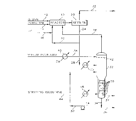
Referring now to FIG. 1 there is shown alkylation reactor 10
which defines an alkylation reaction zone. An olefin feed stream is introduced
into alkylation reactor 10 through conduit 12 and an isoparaffin feed stream is
introduced into alkylation reactor 10 through conduit 14. The olefin feed
~0 generally comprises one or more olefins having from 2 to 5 carbon atoms, while
21 a 2 3 3 7 33363CA
.. ,.. _ S
the isoparaffin stream generally comprises isobutane and/or isopentane. In a
typical operation, the olefin feed comprises a mixture of propylene and
butylenes, while the isoparaffin feed comprises primarily isobutane. A catalyst
comprising hydrogen fluoride is introduced into alkylation reactor 10 through
S conduit 16 and through recycle conduits 18 and 19. In a typical alkylation
process operation, the HF is in the liquid phase and has a purity of at least about
90%. Fresh m~keup catalyst can be introduced as required through conduit 16.
The eMuent from alkylation reactor 10 is passed to a settler 20 in which a phase
separation is made between the acid phase and hydrocarbon phase. The
10 hydrocarbon phase is removed from settler 20 through conduit 22 and passes to
downstream processing.
The acid phase is removed from settler 20 through conduit 24. At
least a portion of the acid phase stream is recycled directly to aLkylation reactor
10 through recycle conduit 19. The rem~in(ler of the acid phase stream is passed
15 through conduit 28, having interposed therein heater 30 defining a heat transfer
zone and providing means for transrelrillg heat to the acid phase stream, to
separator column 32. Separator column 32 defines a separation zone comprising
a top zone, an intermediate zone, and a bottom zone and provides separation
means for separating ASO from the HF of the acid phase. A purified HF stream
20 is removed as an overhead stream from separator column 32 through conduit 18
2 1 5 2 3 37 33363CA
and is recycled to alkylation reactor 10. An ASO stream can be removed as a
bottoms stream from separator column 32 through conduits 34 and 36 or,
alternatively, through conduit 37.
A liquid hydrocarbon reflux is introduced into the top zone of
separator column 32 through conduit 38 having interposed therein condenser 40
defining a heat transfer zone and providing means for l~ ing heat from the
liquid hydrocarbon reflux. The reflux is introduced onto distribution tray 42
located within the top zone of separator column 32. The bottom zone of
separator column 32 is provided with a plurality of vapor-liquid contacting
means, such as fixed valve fractionator trays 50. Stli~phlg isobutane is directed
to the bottom zone of separator column 32 by conduit 44. Interposed in conduit
44 is vaporizer 48 which defines a heat transfer zone and provides means for
he~ting and/or vaporizing the stripping isobutane introduced into separator
column 32.
A bottoms stream comprising ASO is removed from separator
column 32 through conduit 34 and passes downstream by way of conduit 36. As
an additional embodiment of the invention, at least a portion of the bottoms
stream can be recycled or returned to separator column 32 by way of conduit 52.
Interposed in conduit 52 is pump 54 for providing work input required to recyclethe at least a portion of the bottoms stream to separator column 32. The at least
2 i 5 2 3 3 ~ 33363CA
a portion of the bottoms stream is introduced into the intermediate zone of
separator column 32 at a location below the introduction entry point of the acid
phase but above the bottom zone of separator column 32 wherein contained is
a series of vertically spaced, fixed valve fractionator trays 50. A further
S embodiment of the invention includes, optionally, drawing the boKoms stream
from separator column 32 through conduit 37.
FIG. 2 provides an enlarged detail of separator column 32, which
includes the bottom zone, cont~ining the series of vertically spaced, fixed valve
fractionator trays 50. Each of the vertically spaced, fixed valve fractionator
10 trays 50 include a plate or a deck 56 having a thickness and defining therein a
pattern or plurality of apertures 60 (shown in FIG. 3) for permitting the
ulJ~va~ly flow of gas therelllrough. Each individual aperture 60 defined by each
plate 56 represents a cross-sectional area in the range of from about 0.005
square feet to about 0.40 square feet, pr~e~ably from about 0.01 square feet to
about 0.30 square feet and, most preferably, from 0.015 square feet to 0.25
square feet.
Provided with each fixed valve fractionator tray 50 is a downcomer
62. Each downcomer 62 can comprise vertical plates secured along opposite
edges thereof to the interior surface of separator column 32 so as to extend
20 entirely across the interior of separator column 32. The vertical plate of
2152337 33363CA
.~
do~,vncomer 62 extends upwardly above the plane of plate 56 so as to provide an
edge 64, which defines an overflow weir, having a height of from about 0.5
inches to about 4 inches, for retaining a level of liquid upon each plate 56. The
vertical plate of downcomer 62 also extends downwardly to close proximity of
S the fixed valve fractionator tray 50 positioned below. The downcomers 62 are
located on opposite sides of the interior of separator column 32 so as to guide
liquids from a fixed valve fractionator tray 50 above to a fixed valve fractionator
tray 50 below until the liquid passes along the last of such trays and is directed
by its downcomer 62 to the bottom of separator column 32. Thus, the
10 arr~ngement of fixed valve fractionator trays 50 and downcomers 62 provide for
the stair step type flow of liquids down the interior of separator column 32 with
the liquid passing horizontally along each plate 56 and being directed to the tray
below each downcomer 62.
The liquid is held on top of each tray by gases that flow upwardly
15 through separator column 32 and passing through apertures 60. Preferably, the
gas flow through apertures 60 should be sufficient to prevent a substantial
portion of the liquid cont~inP~ on top of each plate 56 to fall through such
apertures and sufficient to m~int~in a level of liquid on top of each tray 50.
The liquid level formed or provided in the bottom zone of
20 separator column 32 primarily contains ASO, but it also contains a co~ce~ ion
~-9 -
33363CA
2152337
,~, ,,
of HF. It has been discovered that at least two liquid phases will form in the
bottom zone of separator colurnn 32. The top phase, or upper phase 66, will
have a concentration of HF that is less than the concentration of HF in the
bottom phase, or lower phase 68. Generally, upper phase 66 will have an HF
S concentration of less than about 20 weight percent, preferably less than about 10
weight percent and, most preferably, less than 5 weight percent. As for lower
phase 68, the HF concentration is greater than the HF concentration of the upper
phase and can be as high as about S0 weight percent.
In one embodiment of the invention, it is important for the bottoms
10 stream drawn from separator column 32 to be taken from upper phase 66 as
opposed to lower phase 68. By removing upper phase 66 as the bottoms stream,
as opposed to lower phase 68, HF loss is reduced due to the lower HF
concentration in upper phase 66. The removal of upper phase 66 as the bottoms
stream in combination with the recycling of lower phase 68, which has a greater
15 concentration of HF than that of upper phase 66, to the intermediate zone of
separator column 32, a signific~nt reduction in HF loss with the bottoms stream
is achieved.
Provided in FIG. 4 is a close-up perspective view of a single
aperture 60 and the associated fixed valve 70. As described earlier herein, each
20 plate 56 shall define a plurality of apertures 60, but associated with each of such
~1 5 2 3 3 7 33363CA
;'i_ 10
aperture 60 is a f~ed valve 64 fixedly spaced above each aperture 60. The fixed
valve 70 has substantially the same shape as its associated aperture 60 and is
provided to direct the flow of the gases which are passing upwardly through
apertures 60 in the horizontal direction parallel to plate 56. This configuration
provides for the intim~te contacting of the upwardly flowing gases with the
liquid flowing across each plate 56. The ~ t~nce of the fixed space above each
aperture 60, as measured by the ~list~n( e from the horizontal plane plate 56 and
the horizontal plane of fixed valve 70, is in the range of from about 0.1 inchesto about 0.5 inches, preferably from about 0.15 inches to about 0.45 inches and,most preferably, from 0.2 inches to 0.4 inches.
An important aspect of the process in the regeneration of an HF
catalyst that contains a concentration of ASO is for the separator column 32 to
be properly equipped with fixed fractionator trays 50 as described herein. It has
been found that the use of such trays in combination with the other features of
the hlventive process provides for a separation of ASO from the ASO-cont~inin~
HF catalyst with a reduction hn the amount of HF that is lost along with the ASOremoved from the ASO-cont~ining HF catalyst.
The ASO-cont~ining HF catalyst is charged to the hntermediate
zone of separator column 32 at a temperature in the range of from about 200~F
to about 300~F, preferably, however, in the range of from 250~F to 295~F.
2152337 33363CA
11
The temperature of the overhead stream of purified HF comprising HF can be
in the range of from about 200~F to about 300~F and, preferably between 250~F
and 295~F.
As for the isoparaffin reflux stream, its temperature can be in the
5range of from about 40~F to about 140~F, preferably, 60~F to 120~F. The
preferred isoparaffin for use as the isoparaffin reflux stream is isobutane.
The ~li~ing isoparaffin stream is introduced into the bottom zone
of separator column 32 at an entry point below the series of vertically spaced,
fixed valve fractionator trays contained within the bottom zone of separator
10column 32, and is in the form of a vapor or a gas. This vaporous isoparaffin
rises upwardly through apertures 60 of each fixed valve fractionator tray 50 andprovides for the separation of ASO and HF from the ASO-cont~inin~ HF
catalyst. The preferred stripping isoparaffin is isobutane, and it can have a
temperature excee ling about 275~F and, preferably, can be in the range of from
15300~F to 400~F.
The pressure at which column 32 is operated can generally be in
the range of from 100 psia to 200 psia, preferably, from 125 psia to 175 psia.
The ASO-cont~inin~ HF catalyst will generally have a
concentration of ASO exceeding about 1.0 weight percent ASO based on the
20 total weight of the ASO-cont~ining HF catalyst. Specifically, the ASO
33363CA
21~23~7
12
concentMtion can be in the range of from about 1.25 weight percent to about 10
weight percent, and, more specifically, it can be in the range of from 1.5 weight
percent to S weight percent.
The overhead stream of purified HF comprising HF shall have a
S conce~ ation of ASO that is lower than that of the ASO-cont~inin~ HF catalyst.
Therefore, the ASO concentration will generally be less than 1.0 weight percent.
As for the bottoms stream of ASO, it is desirable to minimi7e the
amount of ASO in such streams; and, indeed, this is an advantage of the instant
invention in that the amount of ASO that is lost along with the ASO bottoms
10 stream is much less than for other methods of regeneration of ASO-cont~inin~
HF catalyst streams. The bottoms stream will comprise ASO at a concentration
of at least about 50 weight percent based on the total weight of the bottoms
streams. Preferably, the ASO concentration can be at least about 60 weight
percent and, more preferably, it can be at least 70 weight percent.
It is most desirable to minimi7e the concentration of HF in the
bottoms stream in order to also minimi7e the amount of HF lost with the boKoms
stream, thus, the HF concentration can be less than about 50 weight percent of
the boKoms stream, prefer~bly less than about 40 weight percent and, most
preferably less than 30 weight percent.
215 ~ 3 3 7 33363CA
13
As discussed elsewhere herein, it has been discovered that the
liquid level established in the boKom zone of sepaMtor column 32 forms at least
two separate liquid phases, including an upper phase and a lower phase. The
upper phase has a concentration of HF that is smaller than the concentration of
S HF in the lower phase. Generally, the lower phase will have a concentration of
HF that is greater than the concentration of HF in the upper phase. Specifically,
the concentration of HF in the upper phase is less than about 20 weight percent,
~reÇelably, less than about 10 weight percent and, most preferably, less than 5
weight percent. The lower phase has an HF concentration as high as about 50
10 weight percent.
The following examples are provided to further illustrate the
invention and the benefits thereof.
FY~mple I
The example sllmm~rizes the results of an actual installation and
15 operation of the invention at the Phillips Petroleum Company refinery located
at Sweeny, Texas. The process had experienced high acid losses with its use of
a separation column cont~ining therein conventional sloping or inclined trays.
The inclined trays were removed from the separation column and replaced with
fixed valve fractionator trays. After a period of operation, the data clearly
21S2337 33363CA
14
establishes the enormously improved performance of the separation column and
the significant reduction in the loss of HF with the ASO bottoms product.
The following Table I provides actual HF losses for each of six
time periods immediately prior to the modification of the separation column and
5 for each of seven time periods subsequent to the modification of the separation
column. The data show that the average HF lost in the ASO bottoms product
for the conventional process was 34,676 pounds per time period and was
~i~nifir~ntly higher than the average HF loss of 18,633 pounds per time period
after the in~t~ tion and operation of the novel process. These figures amounted
10 to an average acid consumption in the associated alkylation process of 0.12
pounds HF per barrel allylate produced for the conventional process versus 0.06
pounds of HF per barrel aL~ylate produced for the novel process.
21~23~7 33363CA
TABLE I
Time PeriodLBS HF Lost WithLBS Per Bbl Allylate
ASO Product Produced
Old Process
42,420 0.15
2 50,500 0.16
3 26,260 0.09
4 30,300 0.12
26,260 0.08
6 32,320 0 10
Average 34,676 0.12
New Process
17,409 0.08
2 16,796 0.05
3 26,521 0.07
4 21,520 0.06
22,658 0.07
6 16,705 0.05
7 8,827 0.04
18,633 0.06
Example II
2 i a ~ 3 3 7 33363CA
16
This example provides selected values from a calculated material
balance used for designing a revarnp of an acid rerun column of a Phillips
Petroleum Company HF Alkylation Process Unit. The stream m-mbers
correspond to those of FIG's. 1 and 2. As can be seen from the stream
5 compositions, the HF concentration of stream 37 is 0.5 weight percent as
compared with an HF concentration of 10 weight percent for stream 34. This
demonstrates that the upper liquid phase in the bottom liquid level of the acid
rerun column has a lower HF concentration than that of the bottom liquid phase.
Also, the material balance shows that by recycling the bottom phase, HF loss
10 with the ASO product is significantly reduced and minimi7e~1.
L Table II - Selected Stream Compositions
_ _
StreamNo. ¦ 28 ¦ 34 ¦ 36 ¦44~ 37
Components:
(lb/hr)
Hydrogen Pluoride29956.71144.3 0 123.7 3.5
Ethane 0.5 0.0 0 2.5 0.0
Propylene 0.0 ~-~ ~ ~-~ ~-~
Propane 178.8 0.0 0 2281.3 0.0
Iso-Butane 1935.3 0.0 0 25395.2 0.0
Butylenes 0.0 0.0 0 0.0 0.0
Amylenes 0.0 0.0 0 0.0 ~-~
N-Butane 61.7 0.0 0 826.3 0.0
Pentanes Plus 114.8 0.0 0 427.0 0.0
2152337 33363CA
17
Table II - Selected Stream Compositions
Heavy Alkylate 2.4 0.0 0 0.0 0.0
Acid Soluble Oil 1322.0 10299.1 0 0.0661.0
Water 661.0 0.0 0 0.0 0.0
Total 34233.1 11443.4 0 29056.0 664.5
While this invention has been described in terms of the presently
plefelled embodiment, reasonable variations and modifications are possible by
those skilled in the art. Such variations and modifications are within the scopeof the described invention and the appended claims.