Note: Descriptions are shown in the official language in which they were submitted.
2~ 5
TITLE OF THE INVENTION
Refrigerating method and apparatus for showcases and
vending machines as well as open type showcases and vending
machines utilizing said method and apparatus
BACKGROUND OF THE INVENTION:
.
This invention relates to refrigerating method and
refrigerating apparatus of showcases for foodstuff
displaying use or goods containing cases of automatic
vending machines and the like, more specifically method and
apparatus being suitable especially for refrigerating of
cold storage or refrigerating showcases installed for
example in large scale markets, as well as open type
showcases and vending machines utilizing said refrigerating
method and apparatus.
Nowadays when the scale-up of foodstuff shops or
markets is advancing due to lightening of the Large Scale
Shops Regulation, production of refrigerated or chilled
foodstuff is more and more increased in our foodstuff
industry. As a result, showcases for refrigerated foodstuff
and cold-storage foodstuff (these showcases for
refrigerated and/or cold-storage foodstuff being called
hereunder "showcases") are occupying more and more
proportion of the available floor surface of these shops.
These showcases are to refrigerate or cold-store the
215~43S
foodstuff contained therein by means of cold air
refrigerated through refrigerating units constituting a
refrigerating circuit. The refrigerating units comprise
various members such as a compressor, a condenser,
expanding memhers and an evaporator constituting a
refrigerating cycle and connected to each other through a
piping in which a coolant is circulated, and a fan serves
to carry out heat-exchange between coolant in the
evaporator and surrounding medium for refrigerating said
medium.
The operation of the refrigerating cycle is as
follows:
Coolant is first absorbed into the compressor and
compressed therein to a condition of high temperature -
high pressure. Coolant in this condition is forced to pass
through a condenser such as for example capillary tubes and
wherein coolant is subjected to heat-exchange with
surrounding air thereby to cause the medium to radiate and
liquefy. Liquid coolant thus obtained is subjected to
adiabatlc expansion at expansion members such as expanslon
valve thereby to be changed into liquid condition of low
temperature - low pressure. Coolant in this liquid
condition is caused to pass through the evaporator to
absorb heat from surrounding medium to be refrigerated,
thereby to refrigerate said surrounding medium while at the
same time evaporating itself to return to its initial gas
condition. Then coolant in its gas condition is again
absorbed into the condenser for continuing the
-- 2
21~43S
refrigerating cycle.
The refrigerating apparatus of conventional showcases
is now explained below.
The conventional showcases installed in the shops
contained therein the above described expansion members,
evaporator, fans and various controllers. On the other
hand, said compressor with its driving motor was set in a
machinery room set outdoor, and said condenser was set in a
ventilated place such as on the roof. These compressor and
condenser installed outdoor and said expansion members and
evaporator contained in each showcase were connected each
other through a plurality of (coolant) pipings.
In particular, for connecting said compressor to
various mechanical members, use was made of a plurality of
pipings which were to be laid so as to connect branches
from the side of said compressor to each showcase while
preventing leakage of coolant therefrom. Connecting means
for the pipings consisting of copper pipes were welding
between adjacent pipes or mechanical joint members such as
screw. Further, the outer surface of each pipe was covered
by adiabatic members.
In the above refrigerating device, high temperature -
high pressure coolant fed from said compressor through said
pipings was caused to evaporate in the evaporator contained
in the showcase to cause heat-exchange with air in the
goods displaying portion of the showcase thereby to
~ 2 4 3~
refrigerate these goods.
Since temperature of the surface of evaporator for
carrying out heat-exchange with air in the goods displaying
portion in the showcase is generally below ice point, frost
is formed on the surface of evaporator. Consequently, frost
removing operation called "Defrosting" was carried out at
the frequency of one time for 3 - 4 hours. This defrosting
operation is to remove frost on the surface of évaporator
by interruption of cooling cycle in the showcase.
Therefore, a drain pipe had to be set in each showcase for
draining waste water resulting from said defrosting
operation.
The installation of showcases needs various large
works such as coolant pipings, covering of adiabatic
members on the pipings, and drain piping for each showcase
as well as electrical operation for feeding electricity to
each showcase. As a result, once installed, the showcases
could not be shifted easily due to the drain pipes and
electrical distributing cables, and the replacement of
showcases were fairly expensive work.
When the connection of said pipings were carried out
through welding in said coolant piping works, there was a
risk of pipe damages under excessive charges applied to the
connection due to any outer shocks. In the case of screw
connection of said pipings, contraction of pipes such as
copper pipe due to variation of temperature caused
loosening of screws. In any case, leakage of coolant such
~ 21 ~2~3~
as freon gas generates serious environmental problems since
freon gas causes the destruction of ozone layer. Further,
since the number of connections of said pipings were
increased together with the number of showcases, with the
result of higher leakage of coolant and more complicated
maintenance works.
Further, when the above described defrosting has been
carried out for removing frost deposited on the evaporator,
it was inevitable that the temperature in showcase was
increased by 10 - 15 degrees centigrade. But the increase
of temperature caused generally the problems of quality
control such as drip dropping or so called "dripping" of
raw meat or raw fish maintained in a chilled condition. On
the other hand, in the event of trouble with machines in
the showcase, repairing works must have been done in the
shop with corresponding business delay.
On the other hand, concerning to a large number of
vending machines located all over the country and having
each refrigerating unit therein, problems similar to those
of showcases have occurred especially when a plurality of
such vending machines were installed in the same place.
Moreover, the conventional showcase installed in the
shop has a goods take-out port which is opened on the front
surface thereof. Cooled air in the showcase flows out
through the port and the cooled air stays on the passage in
front of the showcase. Accordingly, the cooling efficiency
of the showcase is bad and a person who passes by the
2152~35
by the showcase or takes out some goods from the showcase
feels cold on his feet.
SUMMARY OF TUE INVENTION:
For eliminating the above disadvantages, the invention
has as its object to deliver refrigerating method and
apparatus for showcases and vending machines as well as
open type showcases and vending machines utilizing said
method and apparatus, said showcase and vending machines
having lower running cost and lower initial cost and
permitting to efficiently use their internal space for
goods containing.
For achieving the object described above, according to
Claim 1, the method for refrigerating showcases of the
invention comprises: cooling air within a refrigerating
unit to a temperature below the predetermined temperature
in showcases and feeding said cooled air as refrigerating
source into said showcases through feeding piping; mixing
said cooled air with air in said showcases thereby to carry
out refrigerating in said showcases, while at the same time
collecting said air in said showcases in the same quantity
of said cooled air fed into said showcases as refrigerating
source through collecting piping back into said
refrigerating unit; and cooling said collected cooled air
in said refrigerating unit for using again said collected
and cooled air as refrigerating air.
~52~3~
According to Claim 2, method for refrigerating
showcases described in Claim 1 further comprises
controlling each of automatically air flow volume
regulating means provided respectively in the feeding side
and in the collecting side of each showcase corresponding
to the temperature in each of said showcases; and
regulating supplying and collecting volume of cooled air
proportionally.
According to Claim 3, refrigerating device for
showcases comprises: a plurality of showcases having
respectively cooled air e;ecting port and cooled air
absorbing port; a refrigerating unit located separately
from said showcases and consisting of a refrigerating cycle
having a compressor, a condenser, expansion members and an
evaporator; a feeding piping for feeding cooled air
generated from said refrigerating unit into said respective
showcases through said cooled air ejecting port; and a
collecting piping for collecting said cooled air from said
respective showcases through said cooled air absorbing port
thereof back into said refrigerating unit.
According to Claim 4, refrigerating device comprises:
a plurality of showcases having respectively cooled air
e;ecting port or ports and cooled air absorbing port or
ports; a refrigerating unit located separately from said
showcases and consisting of a refrigerating cycle having a
compressor, a condenser, expansion members and an
evaporator, of cold storage tank for cold storing of
circulated brine, and of a cooled air generating chambers
-- 7
2~2~3~
having each heat exchangers therein for heat exchanging
said brine cold stored in said cold storage tank with air
thereby to generate cooled air for respective showcases; a
feeding piping for feeding cooled air generated from said
refrigerating unit into said respective showcases through
said cooled air e~ecting port; and a collecting piping for
collecting said cooled air from said respective showcases
through said cooled air through said heat exchangers in
said cooled air generating chamber.
According to Claim 5, refrigerating device described
in Claim 4 further comprises: opening and shutting means
provided in each of said feeding piping and said collecting
piping and regulating the opening degree of said feeding
piping or said collecting piping for presetting the feeding
cooled air volume or the collecting coooled air volume
fixed; and at least one automatically air flow volume
regulating devices provided respectively in the feeding
side and in the collecting side of each showcase to
regulate supplying and collecting volume of cooled air
proportionally by means of temperature controlling devices
located in said respective showcases.
According to Claim 6, refrigerating device of
showcases described in Claim 4 or Claim 5 further
comprises: sealed vessels for sealing freezable brine
therein provided in said cold storage tank.
According to Claim 7, refrigerating device of
showcases described in` either of Claim 3 to Claim 6 further
2~2~3~
comprises: said feeding piping and said collecting piping
consisted respectively of cylindrical adiabatic vent pipes,
pairs of adjacent adiabatic vent pipes connected by means
of connecting members inserted respectively into edge
portions of said adjacent adiabatic vent pipes.
According to Claim 8, refrigerating device of
showcases described in either of Claim 3 to Claim 7 further
comprises: said feed piping and said collecting piping
having respectively thereon at least a valve having duct
opening regulation function for regulating the opening
degree of said respective pipings in order to fix the
venting capacity of said cooled air to be fed and said
cooled air to be collected to predetermined values, and
flow rate controlling function for automatically
controlling the flow rate of ducts by means of temperature
controlling devices located in said respective showcases.
According to Claim 9, refrigerating device of
showcases described in either of Claim 3 to Claim 8 further
comprises: said cooled air generating chamber having
therein two heat exchanging chambers independent to each
other, said respective heat exchanging chambers havving
therein said heat exchangers and having thereto connected
said collecting piping, whereby said cold brine for
refrigerating use and hot brine for defrosting use
selectively introduced into said heat exchangers.
According to Claim 10, refrigerating device of
showcases described in Claim 9 further comprises: said
-
2152~5
cooled air generating chamber having therein a cooled air
collectlng chamber located ad~acent to each of said heat
exchanging chambers via a bulkhead and connected to each of
said feeding piping, and said bulkhead comprising an
opening having shutters for selectively carrying out
venting between said heat exchanging chamber and said
cooled air collecting chamber.
According to Claim 11, method for refrigerating
vending machines comprises: cooling air within a
refrigerating unit to a temperature below the predetermined
temperature in vending machines and feeding said cooled air
as refrigerating source into said vending machines through
feeding piping; mixing said cooled air with air in said
vending machines thereby to carry out refrigerating in said
vending machines while collecting said air in said vending
machines in the same quantity of said cooled air fed into
said showcases as refrigerating source through collecting
piping back into said refrigerating unit; and cooling said
collected cooled air in said refrigerating unit for using
again said collected and cooled air as refrigerating air.
According to Claim 12, refrigerating device for
vending machines comprises: a plurality of vending machines
having respectively cooled air ejecting port and cooled air
absorbing port; a refrigerating unit located separately
from said vending machines and having a compressor, a
condenser, expansion members and an evaporator so as to
form a refrigerating cycle; a feeding piping for feeding
cooled air generated from said refrigerating unit into said
-- 10 --
2~ ~2435
respective vending machines through said cooled air
ejecting port; and a collecting piping for collecting said
cooled air from said respective vending machines through
said cooled air absorbing port thereof into said
refrigerating unit.
According to Claim 13, refrigerating device of vending
machines described in Claim 12 further comprises: said
feeding piping and said collecting piping consisted
respectively of cylindrical adiabatic vent pipes, pairs of
adjacent adiabatic vent pipes connected by means of
connecting members inserted into edge portions of said
adjacent adiabatic vent pipes.
According to Claim 14, refrigerating device of vending
machines described in Claim 12 or Claim 13 further
comprises: said feeding piping and said collecting piping
having respectively thereon at least a valve having duct
opening regulation function for regulating the opening
degree of said respective pipings in order to fix the
venting capacity of said cooled air to be fed and said
cooled air to be collected to predetermined values, and
flow rate controlling function for automatically
controlling the flow rate of said cooled air by means of
temperature controlling devices located in each of said
vending machines.
According to Claim 15, open showcase comprises: a
goods display section on the inside of an open goods taking-
out opening; a cooled air feeding port communicating with
-- 11 --
~ 215~43~
said goods display section for feeding cooled air from
outside into said goods dlsplay section; and a cooled air
collecting port communicating with said goods display
section for collecting said cooled air in order to exhaust
it outwards thereby to prevent the leakage of said cooled
air from said goods taking-out opening.
According to Claim 16, open showcase described in
Claim 15 further comprises: air flow rate controlling means
for substantially equalizing respective flow rates of
cooled air fed from said cooled air feeding port and of
cooled air collected from said cooled air collecting port;
and an automatic controlling means of cooled air
circulation while comparing the temperature in said goods
display section with respect to a predetermined
temperature; whereby to stop the feeding of cooled air to
said cooled air feeding port and the collecting of cooled
air from said cooled air collecting port when said
temperature in said goods display section has fallen below
said predetermined temperature as well as to start again
the feeding of cooled air to said cooled air feeding port
and the collecting of cooled air from said cooled air
collecting port when said temperature in said goods display
section has arisen above said predetermined temperature.
Described in Claim 17, vending machines comprises: a
goods containing box formed inside of goods taking out
opening in its opening condition; a cooled air feeding port
communicating with said goods containing box for feeding
cooled air from outside into said goods containing box; a
- 12 -
21~ 2~
cooled air collecting port communicating with said goods
display section for collecting said cooled air in order to
exhaust it outwards; whereby to prevent the leakage of said
cooled air from said goods taking-out opening.
According to Claim 18, vending machines described in
Claim 17 further comprises: air flow rate controlling means
for substantially equalizing respective flow rates of
cooled air fed from said cooled air feeding port and of
cooled air collected from said cooled air collecting port;
and an automatic controlling means of cooled air
circulation while comparing the temperature in said goods
cont~n~ng box with respect to a predetermined temperature;
whereby to stop the feeding of cooled air to said cooled
air feeding port and the collecting of cooled air from said
cooled air collecting port when said temperature in said
goods display section has fallen below said predetermined
temperature as well as to start again the feeding of cooled
air to said cooled air feeding port and the collecting of
cooled air from said cooled air collecting port when said
temperature in said goods display section has arisen above
said predetermined temperature.
When using refrigerating method and refrigerating
device according to the invention, cooled air in respective
showcases is introduced into said refrigerating unit
through said collecting piping, wherein said cooled air is
further cooled by heat exchanging with coolant in said
evaporator or with brine in said heat exchangers. This air
further cooled is fed to respective showcases through said
21~2~35
feeding piping, so that foodstuffs displayed in respective
showcases can be refrigerated without the need of
installing equipments constituting refrigerating cycle in
respective showcases. Foodstuffs contained in vending
machines can be similarly refrigerated.
BRIEF DESCRIPTION OF THE DRAWINGS:
Fig.l is a diagram showing the first embodiment of
refrigerating device of showcase according to the
invention,
Fig.2 is a longitudinal cross section of the first
embodiment of showcase,
Fig.3 is a perspective view of an adiabatic venting
pipe according to the invention,
Fig.4 is a plan view of another type of adiabatic
venting pipe according to the invention,
Fig.5 is a longitudinal cross section of the second
embodiment of showcase according to the invention,
Fig.6 is a circuit diagram of the second embodiment of
showcase according to the invention,
Fig.7 is a perspective view of cooled air e~ecting
duct used in the showcase according to the invention,
21~24~
Fig.~ is a circuit diagram of cooled air generating
chamber according to the invention,
Fig.9 is a diagram showing the relation between fan
and baffle plate or deflector in a cooled air collecting
chamber,
Fig.10 is a perspective view of a air flow controlling
damper or closing valve,
Fig.11 is a cross section taken along line a-a in
Fig.10,
Fig.12 is a longitudinal cross section taken along
line b-b in Fig.ll,
Fig.13 is a plan diagram showlng the rotation of valve
plate, and
Fig.14 is a cross section view of piping of the other
embodiment of the invention.
DETATT~n DESCRIPTION OF THE EMBODIMENTS:
The method and refrigerating device according to the
invention is described hereinbelow referring to the
attached drawings.
- 15 -
~15~43~
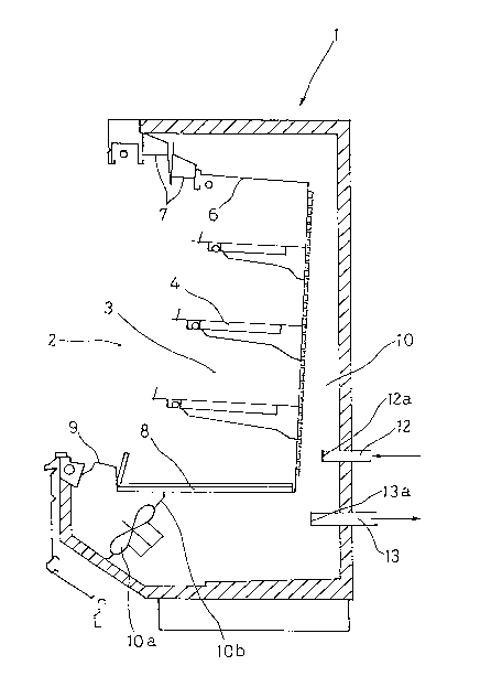
Fig.1 is a diagram of refrigerating device of showcase
according to the invention. As shown in the diagram, a
plurality of showcases 1 is installed in a shop S, with
only a representative showcase 1 shown in Fig.l. Said
showcase 1 is a so called "open showcase" referred to
herein later simply "showcase" unless otherwise specified
and which is built as box type having a part of its front
surface opened as goods taking-out port 2. A goods display
section 3 is formed so as to communicate with said port 2.
In said goods display section 3, a plurality of detachable
shelves 4,4...are located with vertical distances
therebetween. A goods containing box 5 as good displaying
section is located at the bottom of said goods display
section 3 as a portion thereof. As is clear from the
drawings, machines or members used in the known showcases
such as condenser, expansion members, evaporator and the
like are not located in the showcase 1, and no water pipe
for collecting drain water is not connected therein.
Further, the design of said goods display section 3 is not
limited to that shown in Fig.2.
A cooled air e;ecting ports 7 are located on the front
portion of upper wall 6 of said goods display section 3,
while an absorbing port 9 for collecting air used for
cooling goods in said display section 3 is formed on the
front portion of lower wall 8, and this absorbing port 9 is
communicated with air passage 10 formed at the back of said
display section 3.
End portion 12a of a cooled air feeding pipe 12 is
- 16 -
2~2~
located through the rear wall of said showcase 1 to
communicate with the middle portion of said air passage 10.
A baffle plate lOb with a fan 10 is located near said
cooled air absorbing port 9 to communicate with said air
passage 10. End portion 13a of a cooled air collecting pipe
13 is located through the rear wall of said showcase 1 at
the middle position between said fan lOa and said end
portion 12a of said cooled alr feeding pipe 12.
Now referring to Fig.l, in a machinery room M isolated
from said shop S having said showcase 1 contained therein,
a refrigerating unit 11 is set for refrigerating said goods
containing box 5 of said each showcase 1. Said
refrigerating unit 11 comprises the elements constituting
the refrigerating cycle, such as compressor, expansion
members and evaporator as well as motors for driving said
compressor. A condenser is located at a not-shown
ventilated outdoor location. Said compressor and motor can
be lsolated from said expansion members, evaporator and the
like in said machinery room M.
A feeding pipe 12 is connected to said refrigerating
unit 11 for feeding cooled air generated through heat
exchange with coolant of said evaporator in said
refrigerating unit 11 to said goods contA~n~ng box 5 of
said each showcase 1. As described above, the end portion
12a of said feeding pipe 12 is connected to said air
passage 10 of each showcase. Further, said cooled air
collecting pipe 13 communicating with said air passage 10
in each showcase 1 is connected to said refrigerating unit
- 17 -
2~2~
11 for collecting or recoverlng used air in said air
passage 10 of each showcase 1. For establishing a
circulation of cooled air between said refrigerating unit
11 and each showcase 1 through said feeding pipe 12 and
collecting pipe 13, a fan 61 of big capacity for air
feeding and another not-shown fan of big capacity for air
collecting are located in said refrigerating unit 11.
Said air feeding pipe 12 and air collecting pipe 13
comprise respectively a plurality of adiabatic vent pipes
14 connected to each other. Each of said adiabatic vent
pipes 14 has a cylindrical body 15 of foamed adiabatic
material such as urethane. A cylindrical core 16 of resins
such as polyvinyl chloride and the like is inserted into
said body 15 along its internal surface for the purpose of
reducing air resistance. A cylindrical connecting member 17
of polyvinyl chloride and the like resins is inserted into
the end of said body 15 along its internal surface so as to
connect with said core 16. By connecting respective end
portions of adjacent adiabatic vent pipe 14, 14 by means of
connecting member 17 inserted into said end portions and
adhered thereto, said continuous feeding pipe 12 and
collecting pipe 13 are formed. Further, it is preferable to
seal the outer surface of connection between adjacent
adiabatic vent pipes 14, 14 by means of not-shown adhesive
tape and the like. A preferred example of said vent pipe
body 15 has a length of 1 - 1.2 m, an inner diameter of 50 -
600 cm, a thickness of wall of 30 - 75 mm, more preferably
50 - 75 mm, but it is noted that these various sizes are
different between the trunk pipe on the side of
- 18 -
2~243S
refrigerating unit 11 and the branch pipes on the side of
showcases-l. Further, the thickness of said body 15 must be
preferably thicker for lower temperature of cooled air.
On the other hand, at the branching or concentrating
connections, a adiabatic vent pipe 14A of T form as shown
in Fig.4, or a not-shown L pipe or 45 L pipe may be used.
Similarly to said adiabatic vent pipe 14, this adiabatic
vent pipe 14A and other formed adiabatic vent pipe have a
body 15A of foamed adiabatic material such as urethane,
said body having therein a cylindrical core 16 A similar to
said core 16. Said adiabatic vent pipe 14A can be connected
with other adiabatic vent pipe 14, 14A by use of connecting
member 17A similar to said connecting member 17 of Fig.3.
While connecting members 17 are attached to all three
end portions of the adiabatic vent pipe 14 shown in Fig.4,
these connecting members 17 connect with corresponding end
portions of other adiabatic vent pipe 14, 14A having no
connecting members 17. Of course, the three end portions of
said adiabatic vent pipe 14A need not have all
corresponding connecting members 17.
Then, said feeding piping 12 for feeding air cooled in
said refrigerating unit 11 into said showcases 1 and said
collecting piping 13 for collecting air from said showcases
1 are laid so as to build up the circulation between said
refrigerating unit 11 and said showcases 1 installed in
said shop S. At the pipe laying work of said feeding pipe
12 and collecting pipe 13, connecting members 17 are first
-- 19 --
2~ ~243S
inserted into the end portions of adiabatic vent pipe body
15,15A and attached thereto by means of adhesives, and the
outer surface of the obtained connection is sealed by means
of adhesive tape. Piping 14,14A is to be laid out at the
place which does not attract attention and does not impede
clients walk or goods handling.
Operation of the embodiment of the invention having
structural elements as above is described hereinbelow.
Liquid coolant of low temperature and low pressure
generated in refrigerating unit 11 is fed into an
evaporator not shown. Air collected from each showcase 1
into said refrigerating unit 11 through said collecting
pipe 13 is subjected to heat exchange with liquid coolant
passing through said evaporator thereby to cool further the
collected air, and the cooled air thus obtained is fed into
said feeding pipe 12 by means of fan located in said
refrigerating unit 11. Cooled air passing through said
feeding pipe 12 is blown out into said goods containing box
5 through said cooled air e;ecting ports 7. Since these
ejecting ports 7 are set in the upper front portion of said
showcase, ejected cooled air flows from the upper portion
of said goods display section 3 to the lower portion
thereof, while cooling the goods contained therein. Air
used for goods cooling is absorbed through said absorbing
port 9 by means of said fan 10a thereby to be fed into
collecting pipe 13 at the rear side of said goods
displaying section 3 and finally to be returned to said
refrigerating unit 11. As described above, cooled air is
- 20 -
2~ ~243~
caused to circulate between refrigerating unit 11 and each
showcase through feeding pipe 12 and collecting pipe 13
thereby to cool goods contained in said goods display
section 3 to a predetermined temperature.
Further, desired cooling temperatures are different
depending on the cooled goods, for example in general
cooling temperature in the order of -25 degrees centigrade
being preferable when using said showcase 1 as cold-storage
box, temperature in the order of -3 degrees centigrade
being preferable for raw foodstuff such as raw meat and raw
fish and temperature in the order of 10 degrees centigrade
in centigrade being preferable for usual foodstuffs such as
milk and bean curd.
Now, two refrigerating units 11, one for cold storage
of refrigerated foodstuff and another for double use as
cold stooge box of raw foodstuff or refrigerator of usual
foodstuff, are prepared, thereby to feed cooled air of
desired respective temperatures into a desired showcase 1
either for using this showcase 1 as cold-storage box or as
refrigerator. A common compressor can be used even when two
types of refrigerating units are used as in this case.
The showcase 1 according to the invention consists of
display shelves of simple construction having only said
cooled alr ejecting ports 7 and said absorbing port 9 and
having no evaporator, so that laying of drain pipes,
electrical distributing work and coolant pipe laying work
are not necessary. As a result, said showcase 1 can be
- 21 -
~1~2~5
shifted to any desired places. Said adiabatic vent pipes
14,14A connecting said refrigerating unit 11 of said
machinery room with said showcase 1 within shop S can be
easily laid, and said adiabatic vent pipes 14,14A can be
produced at low cost.
Further, according to the invention, the machinery
such as expansion members, evaporator and the like which
were installed in each conventional showcases are
concentrated into said machinery room M wherein
refrigerating cycle can be carried out as a whole, so that
the number of manufacturing components of showcase itself
is reduced with the manufacturing cost reduced
considerably. In other words, for installing 100 showcases
in the heretofore known technics, respective 100
evaporators, 100 expansion members and the like were needed
corresponding to the number of showcases to be installed.
On the other hand, according to the invention, only one set
of refrigerating unit 11 (for one temperature to be set) in
said machinery room M can carry out sufficient functions
independently of the number of showcases. Further the
simple construction of showcase itself allows for smaller
floor space thereof with more efficient utilization of sale
floor surface in the shop.
Further, concentration of refrigerating cycle into the
machinery room M eliminates the need of laying coolant
pipes, drain pipes and electrical distribution lines for
each showcase, so that it is possible to reduce the
equipment cost and also the running cost such as the
- 22 -
2152435
operation maintenance cost for preventing any troubles.
Laying of coolant pipes is constantly set in machinery room
M, so that there is no risk of gas leakage at the shift of
showcases 1 as in the conventional shops, and since there
is fewer connection points due to considerably shorter
lengths of coolant pipes, gas leakage is further reduced.
Further, since there is no need to take the pressure loss
of coolant in the pipes into capacity planning, production
capacity is increased by 25 - 30~.
Further, said defrosting operation in each showcase is
not necessary due to concentrated control in machinery room
M, so that a better temperature control in showcases is
obtained with no risk of "dripping" and with better quality
control of goods.
The first embodiment of the invention described above
can be naturally applied to vending machines.
The second embodiment of the invention is shown in
Figs.5 to 13, wherein Fig.5 shows a showcase used in the
second embodiment and Fig.6 shows a cooling circuit diagram
of refrigerating unit 11 used also in the same second
embodiment.
As shown in Fig.5, a cooled air passage 18 is located
along the upper wall, the rear wall and the lower wall of
goods display section 3. End portion 12a of a cooled air
feeding pipe 12 passing through the rear wall of said
showcase 1 is connected with the middle portion of said air
- 23 -
21~2~35
passage 18. Cylindrical cooled air ejecting duct 19 made of
adiabatic-material such as urethane as shown in Fig.7 is
connected to said end portion 12a so as to be located
horizontally in the width direction of said showcase 1 with
a bending of 90 degrees. Said cooled air ejecting duct 19
has on its upper surface a plurality of ejecting holes 20
formed so as to eject upwards cooled air fed through said
feeding pipe 12 and has on its lower surface a plurality of
discharge holes 21 formed so as to e;ect cooled air
downwards as well as to discharge water from said ejecting
duct 19.
Cooled air e~ecting ports 22 are located at the front
upper end of said air passage 18 for ejecting cooled air
downwards in the front side of said goods display section
3, while a cooled air absorbing port 23 is located at the
lower end of the front side of said goods display section 3
so as to open into the lower front end of said air passage
18. A baffle plate 24 is located on the side of said air
absorbing port 23 far from said cooled air e~ecting duct
19, and a fan 25 is set on said baffle plate 24 for
ventilating said air passage 18.
End portion 13a of an cooled air collecting pipe 13 is
located so as to pass through the rear wall of said
showcase 1 at the intermediate position between said fan 25
and said end portion 12a of said feeding pipe 12. A
cylindrical cooled air collecting duct not shown made of
adiabatic material such as urethane is connected to said
end portion 13a so as to be located horizontally in the
- 24 -
2~43~
width direction of said showcase 1 with a bending of gO
degrees. This air collecting duct has on its underside
surface a plurality of air absorbing holes, said holes
having a hole surface equivalent to the total hole surface
of said cooled air ejecting ports 20 and said discharge
holes 21 on said cooled air ejecting duct 19.
Said cooled air ejecting duct 19 and said air
collecting duct can be similarly connected respectively to
said end portion 12a of feeding pipe 12 and said end
portion 13a of said air collecting pipe 13 described in
said first embodiment.
An air guide passage 26 is located along and on the
rear side of said cooling air passage 18. A guide air
e~ecting port 27 is located at the upper front end of said
air guide passage 26 so as to open in front of and adjacent
to said e~ecting port 22 for e~ecting downwards cooled air
from said guide passage 26, while a guide air absorbing
port 28 is located at the lower front end of said air guide
passage 26 so as to open in front of and adjacent to said
absorbing port 23 for absorbing cooled air flowing in said
goods display section 3. Further, a fan 30 for guide air
venting is supported on a supporting plate 29 adjacent to
said guide air absorbing port 28. Said air guide passage 26
may be omitted depending on the type of showcase 1.
An outer air passage 31 is located above the top end
of said air guide passage 26, and an outer air ejecting
port 32 is formed at the front end of said outer air
- 25 -
21~2~5
passage 31 ad~acent to said guide air ejecting port 27 for
e~ecting downwards outer air fed from said outer air
passage 31. A fan 33 for sucking outer air into said outer
air passage 31 is located on the top plate of said showcase
1. .
A detector 34 consisting of thermostat T for
temperature control of said goods display section 3 is
located at the rear top end of this section 3.
Said feeding pipe 12 and said collecting pipe 13 have
respectively thereon manually operated control valves 49 as
air flow control means for controlling the opening of said
pipes 12,13 so as to approximately equalize the flow rates
of fed air and collected air based on determining of
internal pressures in said pipes before starting the
operation of refrigerating device, and automatic closing
valves 50 as automatic cooled air controlling means driven
by a motor Mo connected to said thermostat T located within
said showcase 1. When temperature in said showcase
detected by said detector 34 of thermostat T located in
said showcase 1 is increased over a predetermined upper-
limit temperature, said closing valves 50 of said feeding
pipe 12 and said collecting pipe 13 are simultaneously
opened, while on the other hand when said thermostat T has
detected a predetermined lower-limit temperature, said
closing valves 50 are simultaneously closed. Said manually
controlled opening control valve 49 and said automatic
closing valves 50 interlocked with said thermostat T in
said showcase 1 can be together replaced by an automatic
- 26 -
~1~2~3~
opening control valve connected with said motor M
constructed as a step-motor for carrying out both valve
opening control function and valve closing function.
Further, said opening control valves 49 and said closing
valves 50 may be located within said showcases 1.
As shown in Fig.6, a refrigerating unit 11 for
refrigerating said goods containing box 5 in said showcase
1 is installed in a machinery room M separated from shop S
having showcases 1 therein installed.
This refrigerating unit 11 consists of a casing 35
containing refrigerating cycle 35 comprising a compressor,
a condenser, expansion members and an evaporator, a cold
storage tank 36 for keeping brine cooled by said
refrigerating cycle 35 in a cool state, and a cooled air
generating chamber 37 for generating cooled air by heat
exchange between said brine and surrounding medium to be
cooled passing through a heat-exchanger 39. In this case,
said condenser in said refrigerating cycle 35 is separately
located as in cooling tower on the roof of said
refrigerating unit 11 and the like.
In said refrigerating unit 11, various equipments
constituting said refrigerating cycle 35 such as
compressor, condenser, expansion members and evaporator are
connected each other through two pipings not shown in the
drawings, while said refrigerating cycle 35 and sald cold
storage tank 36 containing therein a plurality of cold
storage members 38 are connected each other through pipings
- 27 -
21~2~3~
P1, Pl for circulating brine, and further said cold storage
tank 36 and respective heat exchangers 39 in said cooled
air generating chamber 37 are connected through two pipings
P2, P2 for circulating brine. A pump not shown in drawings
serves to circulate brine through said casing 35a, said
cold storage tank 36 and said cooled air generating chamber
37.
Said refrigerating unit 11 is now described in more
details.
For the purpose of cooling said brine as refrigerating
medium in said refrlgerating cycle 35, said brine comes
into contact with a not-shown evaporator of the cycle 35
for heat exchange in said casing 35a. In this embodiment,
it is preferable to use calcium chloride having a
characteristic of becoming hardly viscous or ethylene
glycol solution as brine.
In said cold storage tank 36 which is connected to
said refrigerating cycle 35 through 2 pipings Pl, Pl for
circulating brine, there are arranged in parallel a
plurality of cold storage vessels 38a which enclose each a
solution of ethylene glycol mixed with water so as to
obtain a liquid having a little higher freezing point (-30
to -40 degrees centigrade). Aligning direction of said cold
storage vessel 38a is parallel to the opposing side surface
36a,36a receiving said pipings Pl and P2 for the purpose of
accelerating the flow of brine through said casing 35a,
said cold storage tank 36 and said cooled air generating
- 28 -
21~2~3~
chamber 37. Further, polyprene glycol, sodium chloride,
magnesium-chloride and the like can be used as brine in
addition to said calcium chloride or ethylene glycol.
Said cold storage tank 36 is connected with a heat
exchanger 39 through two pipings P2, P2, and said pipings
P2 have respectively thereon a closing valve 50A
automatically closed by a not-shown motor connected with
said thermostat T placed in a cooled air collecting chamber
41 and a pump 51 for circulating cooled brine in said cold
storage tank 36. When temperature of generated cooled air
detected by said thermostat T located in said cooled air
collecting chamber 41 is increased above an upper-limit set
temperature, said closing valve 50A is opened and said pump
51 is started on said piping P2, while when said thermostat
T detects a lower-limit set temperature, said closing valve
50A is closed and said pump 51 is stopped on said piping
P2.
Further in said cooled air generating chamber 37, two
heat exchanging chambers 40 having respectively fin coils
39a for circulating said brine are located as shown in
Fig.8. Said heat exchanging chambers 40,40 are separated
from said cool air collecting chamber 41 by a bulkhead 42,
and a fan 43 for venting cooled air is formed on said
bulkhead 42. Said fan 43 has thereon a remote controlled
shutter 44 for shutting venting between said heat
exchanging chambers 40 and said cooled air collecting
chamber 41.
- 29 -
2 1 ~ 2 4 3 ~
Cooled air generated from said heat exchanging
chambers 40,40 are collected into said cooled air
collecting chamber 41 by means of said fan 43.
It is possible to drive simultaneously said heat
exchangers 39 in said both chambers 40, but it is more
preferable according to the invention to use a heat
exchanger 39 in either one of said heat exchanging chambers
40,40 and to carrying out defrosting operation on the heat
exchanger 39 in the other heat exchanging chamber 40 or to
leave said other heat exchanger 39 in the standby state,
thereby to use alternatively said two heat exchanging
chambers 40.
At said defrosting operation, it is possible to close
said shutter 44 thereby to prevent warmer air generating at
this defrosting operation from intruding into said cooled
air collecting chamber 41.
A piping P3 for supplying and collecting hot brine is
located on said piping P2, and a valve 45 on said piping P3
for defrosting use can be opened for carrying out the
defrosting pperation. Calcium chloride as brine is filled
in said piping P3, and this brine is sub;ected to heat
exchange with high temperature - high pressure coolant gas
before said condenser in said refrigerating cycle 35,
thereby to be heated up to about 40 degrees. Further, the
temperature control of said brine can be carried out by
providing a bypass in said piping P3. Said valve 45 of
defrosting use can be replaced by a three-way valve
- 30 -
21~2~3~
combining said defrosting valve 45 and a manually operated
closing valve 49.
Said feeding pipe 12 is connected between said cooled
air collecting chamber 40 and said goods display section 3
of said showcase 1 for feeding cooled air contained in said
chamber 41 into said latter section 3. Said end portion 12a
of said feeding piping 12 communicates with said cooled air
passage 18 in said respective showcases 1.
A venting sensor 60 is located on said feeding piping
12 at the point approximate to said cooled air collecting
chamber 41 for invertor driving a motor Mo of said fan 61
only when the flow rate of cooled air is below a
predetermined value, thereby to preventing the overcharge
of said motor Mo.
Further, said collecting pipe 13 ls connected with
said heat exchange chamber 40 of said cooled air generating
chamber 37 for recycling warmed air from said goods
containing box 5 to said cooled air generating chamber 37
of said refrigerating unit 11. For establishing such a
circulation of cooled air between said feeding pipe 12 and
collecting pipe 13, fan or fans of large capacities not
shown are located in said refrigerating unit 11 except said
fan 43.
Surrounding walls 46 of said cooled air generating
chamber 37 are formed by adiabatic panels, and the ceiling
of said chamber 37 is covered by ceramic plate 47a for
213~D~3~
preventing frosting as shown in Fig.9. Since the ceramic
material of said ceramic plate 47a has such characteristics
as to prevent development of ice crystals contained in
cooled alr striking the same, frosting on said ceiling 47
is prevented. Said ceiling 47 has also an inclined baffle
plate 48 attached thereto for receiving cooled air blown
through said fan 43 located on said bulkhead 42, thereby to
prevent frosting on other internal surfaces other than said
ceiling 47.
Further, said cooled air collecting chamber 41 has
therein said thermostat T for detecting temperature of
generated cooled air thereby to drive said closing valve
50A and said pump 51.
As describe above, said feeding pipe 12 and said
collecting pipe 13 consist respectively of a number of
adiabatic vent pipes 14 having the same structure of those
used in the first embodiment. However, said adiabatic vent
pipes 14 of said feeding pipe 12 do not use any metallic
members such as stainless steel as their cylindrical cores
16 for the purpose of preventing frosting.
Fig.10 is a perspective view of said closing valve 50,
Fig.ll being a cross sectional view taken along the line a-
a of Fig.10, and Fig.12 being a longitudinal sectional view
taken along the line b-b of Fig.ll, respectively.
Valve body 52 of said closing valve 50 is mounted on
the internal surface of said adiabatic vent pipe 14, and
2~243~
said valve body 52 has therein equipped with a circular
valve plate 53 for closing said adiabatic vent pipe 14 and
shutting off venting therein, sald valve plate 53 being
mounted rotatably in a horizontal direction on an
insulation shaft 54 as described above. Two circular valve
seats 55 are located on the inner surface of said adiabatic
vent pipe 14, one valve seat 55 resting on one of circular
portions of said valve plate 53 from the side of said valve
plate 53, and the other valve seat 55 resting on the other
circular portion of said valve plate 53 from the other side
of said valve plate 53. Said circular valve~ seats 55 play
the role of stoppers for stopping the rotation of said
valve plate 53 at about 90 degrees on the opening of said
valve plate 53, while having the function of shutting air
flow around said valve plate 53 by abutting against the
circumferential portion of said valve plate 53 together
with the function of seal members for preventing the
freezing of said valve plate 53 due to the cooling air
supplied from said showcase 1.
Said insulation shaft 54 extends above from the top of
said valve plate 53 into and through said valve body 52,
and has a driving shaft 56 of said motor connected at the
top thereof. Said insulation shaft 54 and said driving
shaft 56 are accommodated in a motor mounting table 57 of
adlabatic material having a cross section of substantially
square form.
Further, said adiabatic vent pipe 14 has a half
construction consisting of upper and lower halves at the
- 33 -
21~24~
point where said closing valve 50 is set thereon, and these
halves are bonded to each other to form a circular cross
section after said valve plate 53 and the like have been
mounted into said adiabatic vent pipe 14.
A small hole opening into the center of duct as flow
rate detecting port 58 is located near said motor mounting
table 57. An air flow meter is inserted from said port 58
into said duct 14 to detect air flow capacity and velocity
therein. On the basis of this flow air detection, a duct
opening regulation valve 49 located in said duct is
manually controlled to obtain an appropriate supplying and
collecting capacity of cooled air. After this appropriate
setting of said regulation valve 49, said flow rate
detecting port 58 is usually closed by a suitable plug 59.
Said insulation shaft and other members constituting
said closing valve 50 is formed from adiabatic materials of
low heat transfer coefficient such as urethane, polyester
and the like.
The operation of the embodiment described above is as
follows:
Liquid coolant in low temperature/low pressure state
ln said refrigerating cycle 35 of said refrigerating unit
11 is first fed into a not-shown evaporator, wherein said
coolant is forced to come into contact with brine, so that
calcium chloride as brine is cooled up to -40 to -50
degrees centigrade. Brine thus cooled is circulated into a
2152~3$
cold storage tank 36 through piping P1 for cold storage
therein. -
Calcium chloride solution thus cooled freezes amixture of ethylene glycol and water which has been
beforehand regulated so as to freeze at -30 to -40 degrees
centigrade, i.e. at a little higher freezing point than
that of calcium chloride contained in said cold storage
vessels 38a. Therefore, when said calcium chloride as brine
has been a little warmed through circulation thereof, said
cold storage vessels 38a take the role of cold storage
members 38 for cooling said brine down to -40 to -50
degrees centigrade. Therefore, there is no need to
continuously drive said refrigerating cycle 35. In other
words, only in the case where said calcium chloride
solution becomes so warm that it can not generate cooled
air of predetermined temperature in said cool air generator
37, said refrigerating cycle 35 is driven for cooling
calcium chloride solution while operating said closing
valve 50 in said piping P2 for circulation of said
solution. Said mixture of ethylene glycol and water in said
cold storage vessels 38a can be freezed by using the
midnight electricity of low price, and, at the day time,
said refrigerating cycle 35 is driven only when the
temperature of brine becomes lower than the predetermined
temperature.
Cooled air collected from each showcase 1 through said
collecting piping 13 into said cold air collecting chamber
41 is cooled then by heat exchanging with brine passing
21~2~35
through said cooling fin coils 39a located in said cooled
air generating chamber 37, and air thus recooled is fed
into said feeding piping 12 by means of a fan not shown in
said refrigerating unit 11. Cooled air fed into piping 12
is ejected through said ejecting duct 39 evenly into said
cooled air passage 18 and then from said ejecting port 7
into said goods display section 3. Since said cooled air
ejecting port 7 is located at the upper front edge of said
showcase 1, it descends downwards from the upper portion of
said goods display section 3, while cooling this section 3
and goods contained therein. Cooled air used for goods
refrigerating is absorbed through said absorbing port 9
located at said goods containing box 5 into said collecting
piping 13 by means of another fan located in said
refrigerating unit 11, and then into said refrigerating
unit 11.
As described above, cooled air is forced to circulate
through said feeding piping 12 and said collecting pipe 13
each consisting of adiabatic vent ducts 14, 14a for cooling
goods arranged in said goods display section 5 to a
predetermined temperature. On the other hand, air used for
cooling is absorbed from said absorbing port 9a into said
cooled air passage 18 by a fan 25 and can be reused as
cooled air after mixing with fresh cooled air fed from said
feeding piping 12 into said cooled air passage 18.
Guide air ejecting port 7b and outer air e~ecting port
7c located at the front portion of upper wall 6 of said
goods display section 3 eject respectively guide air and
. - 36 -
21~243~
outer air as air curtain for assuring the balance between
pressures of cooled air and outer air. Said guide air and
its surrounding air is absorbed through said guide air
absorbing port 9b located at the front portion of lower
wall 8 in said goods display section 3 into said guide air
passage 26 by means of said fan 30 to be fed again from
said guide air e~ecting port 27 as guide air after passing
through said guide air passage 26.
Further, it is to be noted that due to the opening
control of said feeding pipe 12 and said collecting pipe 13
by means of said duct opening regulation valve 49, feeding
capacity and collecting capacity of said cooled air is
approximately equal to each other, and balance between
pressures of outer air and cooled air is ad~usted with said
guide air as said air curtain ejected in front of said
showcase 1.
Once temperature in said showcase 1 descends down to
the predetermined lower limit temperature while driving
said refrigerating cycle 35 in said refrigerating unit 11,
venting through said adiabatic vent pipe 14 is closed by
stopping driving of said motor M located on said feeding
piping 12 and said collecting piping 13 and connected to
said thermostat T for controlling the temperature in said
showcase l thereby to force said valve plate 55 to abut
onto said valve seats 55. On the other hand, when the
tempera~ure in said showcase 1 increases above the
predetermined upper limit temperature, said motor Mo is
driven thereby to rotate said valve plate 53 of said
2~2~
closing valve 50 by about 90 degrees for establishing
venting of said adiabatic vent pipe 14 and for feeding
cooled air into showcase 1 while collecting cooled air used
in said showcase 1.
In this second embodiment of the invention, by
providing two set of refrigerating units 11, one for
foodstuff freezing and another for joint use as foodstuff
freezer and refrigerator as described in the first
embodiment, cooled air of desired temperature can be
generated and introduced into desired showcase 1 through
feeding piping 12 thereby to desirably use said showcase 1
as freezer or refrigerator.
It is possible to shift said showcases 1 to desired
position and to lay simply said adiabatic vent pipe 14, 14A
connecting said refrigerating unit 11 in said machinery
room M with said showcase 1 in said showcases in said shop
S.
Further, said refrigerating cycles 35 in respective
showcases 1 have been assembled in said machinery room M as
a unit, so that the number of manufacturing parts of said
showcase 1 itself is decreased thereby to attain a lower
manufacturing cost. The simple construction of showcase
itself thus obtained permits a smaller installation space
thereof thereby to render possible the more efficient
utilization of sale floor surface of said shop S.
Further, concentration of refrigerating cycle into the
- 38 -
21 ~2~35
machinery room M eliminates the need of laying coolant
pipes, drain pipes and electrical distribution lines for
each showcase, so that it is possible to reduce the
equipment cost and also the running cost such as the
operation maintenance cost for preventing any troubles.
Laying of coolant pipes is constantly set in machinery room
M, so that there is no risk of gas leakage at the shift of
showcases 1 as in the conventional shops, and since there
is fewer connection points due to considerably shorter
lengths of coolant pipes, gas leakage is further reduced.
Further, a considerable length of coolant piping has
been necessary for the heretofore known refrigerating
device, for example for a coolant piping of 80 meters, a
capacity loss of about 30% had to be anticipated for a
driving force of refrigerating device less than 10 horse
powers. On the other hand, the refrigerating device
according to the embodiment has a design of compact sizes
and less pressure loss of pipings without need of capacity
loss.
The defrosting operation in each showcase is not
necessary due to concentrated control in machinery room M,
so that a better temperature control in showcases is
obtained with no risk of "dripping" and with better quality
control of goods.
By using mldnight electricity for cooling brine to be
used and using said cold storage vessels 38a thus freezed
as cold storage members 38 for brine, it is not necessary
- 39 -
3~
to continuously drive said refrigerating cycle 35 thereby
to decrease the total cost of electricity to 40 - 50~ of
that of heretofore known showcases.
Further, the heat exchanging between brine and water
using fin coils 39a for generating of cooled air allows for
a higher heat exchanging coefficient, so that the
evaporator heretofore used can be reduced in size to about
1/3.
In the second embodiment each valve plate 53 of the
closing valves 50 of said feeding pipe 12 and said
collecting pipe 13 rotates 90 degrees only to open or shut
the opening of the pipes 12,13. But it is possible to
rotate each of said valve plate 53 of said closing valves
50 of said feeding pipe 12 and said collecting pipe 13
within 90 degrees to change an opening degree of said
opening widely or narrowly by said step-motor Mo
corresponding to the temperature in each of said showcases
1.
By this construction , once temperature in said
showcase 1 descends down to the predetermined lower limit
temperature while driving said refrigerating cycle 35 in
said refrigerating unit 11, the opening degree of the
opening is closed narrowly by rotating the valve plate 53
of the closing valves 50 of the feeding pipe 12 and the
collecting pipe 13 by driving the step-motor Mo. Then the
supplying and collecting volume of cooled air into and out
from the showcase 1 are reduced in quantity and the
-- 40 --
2~2~5
temperature in the showcase 1 begins to increase slightly
little by little.
On the other hand, when the temperature in said
showcase 1 increases above the predetermined upper limit
temperature 1 while driving said refrigerating cycle 35 in
said refrigerating unit 11, the opening degree of the
opening is opened widely by rotating the valve plate 53 of
the closing valves 50 of the feeding pipe 12 and the
collecting pipe 13 by driving the step-motor Mo. Then the
supplying and collecting volume of cooled air into and out
from the showcase 1 are gained in quantity and the
temperature in the showcase 1 begins to descend slightly
little by little.
In this embodiment of the invention, it is possible to
control the temperature in the showcase 1 within 1 degree.
Fig. 14 shows the other embodiment of the invention
instead of rotating each of said valve plate 53 of said
closing valves 50 of said feeding pipe 12 and said
collecting pipe 13 within 90 degrees to change an opening
degree of said opening widely or narrowly by said step-
motor Mo corresponding to the temperature in each of said
showcases 1.
In said feeding pipe 12 and said collecting pipe 13
for each of said showcase 1 there are no closing valves 50
but there provided a fun 70 which is driven by a motor FM.
Said motor FM is connected to a thermostat in corresponding
- 41 -
21~i2~3~
showcase and controlled by an inverter. Accordingly, the
number of rotation of said motor FM can be changed
corresponding to the temperature in each of said showcases.
In said feeding pipe 12 and said collecting pipe 13
for each of said showcase 1 there provided a remote
controlled shutter 71 near the fun 70 for shutting said
feeding pipe 12 and said collecting pipe 13 when said fun
70 is not driven.
By this construction, once temperature in a showcase
descends down to the predetermined lower limit temperature
while driving said refrigerating cycle 35 (Fig.4) in said
refrigerating unit 11 (Fig.1), the number of rotation of
said motor FM is decreased. Then the supplying and
collecting volume of cooled air into and out from the
showcase by rotating of said fun 70 are reduced in quantity
and the temperature in the showcase begins to increase
slightly little by little.
On the other hand, when the temperature in a showcase
increases above the predetermined upper limit temperature
while driving said refrigerating cycle 35 in said
refrigerating unit 11, the number of rotation of said motor
FM is increased. Then the supplying and collecting volume
of cooled air into and out from the showcase by rotating of
said fun 70 are gained in quantity and the temperature in
the showcase begins to descend slightly little by little.
In this embodiment of the invention, it is possible to
- 42 -
- 2152~5
control the temperature in the showcase within 1 degree.
The invention is not limited to the above described
embodiments. For example, the invention is not limited to
the open showcases as described above, but it can be
applied to cooling of vending machines or of closed type of
showcases having front doors. It is to be noted that two
set of said refrigerating chambers are not necessarily used
in the refrigerating devices of said vending machines.
The advantages obtained according to the invention is
that a number of refrigerating equipments can be
concentrated into a single machinery room, that no pressure
loss is caused in coolant pipings of refrigerating devices,
and that cold storage of brine can be carried out by
utilizing of midnight electricity thereby to reduce the
total necessary electricity by 40 - 50%. Further, when
using the refrigerating devices according to the invention
are used as showcases, the laying operation of coolant
pipings, electric works or drain pipe works is not
necessary in shops, and shifting of showcases in shops and
the following piping works can be easily carried out. Since
cooled air is circulated between refrigerating device and
respective showcases, there is no danger of leakage of
coolant in the pipings, which is a factor contributing to
the environmental protection.
Further, since showcases and vending machines with a
simplified construction can increase the goods capacity for
a same occupying space thereof and can decrease the
- 43 -
-
21~43~
occupying floor space thereof for a same goods capacity,
thereby to deliver a larger sale floor space in the case of
showcases. Defrosting operation is not necessary due to the
concentration of refrigerating devices into a single
refrigerating unit in said machinery room, so that
freshness control of goods contained is improved.
Furthermore, the number of refrigerating parts, the
frequency of faults and the running cost such as
maintenance can be reduced.
- 44 -