Note: Descriptions are shown in the official language in which they were submitted.
WO 37-A1/Lm 2 1 5 2 4 4 3
" An Interactive Respiratory Regulator
The invention relates to an interactive respiratory
regulator for relaxation purposes comprising:
- a recording device recording the respiratory pat-
tern of a user and producing a corresponding respiratory sig-
nal,
- an instruction signal generator for generating an
instruction signal that can. be perceived by the user in order
to influence his respiratory behaviour,
- a control device controlling the instruction signal
generator,
- a processing device which determines by means of a
parameter of the respiratory signal received whether the res-
piratory pattern recorded during a predetermined time span
meets a preadjustable standard for this parameter, and which
at a certain error percentage sends a starting signal to the
control device.
An apparatus of this kind, indicating to a user a
desirable respiratory pattern, is known from the Netherlands
patent specification 166.850, whereby this apparatus, in par-
2o ticular to cambat the hyperventilation syndrome, is provided
with a device for determining the cycle time. The correspond-
ing frequency of the respiratory cycles is applied as parame-
ter for the respiratory pattern. The recording device, being
for instance a strain gauge or a mercury wire recorder applied
to the chest of the user, produces a pulse signal with a
repeat frequency corresponding with the respiratory frequency.
This signal is fed to a time-determining device which compares
this frequency with a preset standard or limit value. As soon
as this prQCessing device determines that the respiratory fre-
quency is higher than the limit frequency it will set off a
sound generator which during each respiratory cycle produces
two, for the patient audible and differentiable tones.
However, not only patients suffering from hyperven-
tilation, the symptom of which is an abnormally high respira-
tort' frequency, exhibit a non-optimal respiratory behaviour,
but also users who suffer, for instance, from respiratory
sinus-arrhythmic deficiency, CNSLD or phobias or psychic trau-
:~as of any kind. Also users with a respiration which occurs
WO 94J14374 ~ ~ ~ ~ 't 3 PCT/NL93J00273 ..a_ ...._
2
mainly via the chest as opposed to abdominal respiration, have
a form of non-optimal respiration, because in order for all
organs to be well supplied with blood an effective abdominal
respiration is important.
Describing the pattern of such a non-optimal respira-
tion solely in terms of respiration frequency was shown not
always to be adequate. The present invention ensues from the
search for a useful, instructive feed back to the user with
non-optimal respiratory patterns including others besides
those which occur through hyperventilation. On these grounds
it has been concluded that in order to analyze a respiratory
pattern correctly, knowledge of especially the ratio between
the in- and exhalation times is indispensable. The pause after
exhalation is also an important parameter.
The known apparatus described above has, however, the
limitation that it does not include that necessary extra in-
formation in the feed back process, thus offering insufficient
possibilities for application to remedy disorders or to cor-
rect deficient respiratory patterns in general.
The object of the invention is to provide an appara-
tus in accordance with the kind mentioned in the preamble,
which analyzes a user's recorded respiratory pattern in more
detail and which not only tests a threshold with respect to
the respiratory frequency.
To this end the interactive respiratory regulator
according to the invention is characterized in that the pro-
cessing device processes as parameter the ratio between the
in- and exhalation time in a respiratory cycle, and optional-
ly the pause after exhalation.
In a preferred embodiment the processing device in-
cludes the frequency of the respiratory cycles as a second
parameter and the preadjustable standard also comprises a
value for this parameter.
This apparatus can offer the user suffering from any
kind of respiratory regularity disorders the advantage of use-
ful feed back. Thus the apparatus offers a wide range of ap-
plicability not only with hyperventilation, but in principle
with any non-optimal respiratory behaviour. The interactive
respiratory regulator can, for instance also be used by people
who, especially in the case of continual stress, wish to
WO 94/14374 ~ ~ 5 2 ~+ 4 3 PCT/NL93/00273
acquire a healthy manner of respiration. In addition the in-
teractive respiratory regulator can be used for the detection
of sleep apnoea and if so detected will, by registering the
duration of non-respiration, emit a signal until respiration
is resumed, while optionally also the frequency of apnoea oc-
currence can be recorded. Thus the apparatus according to the
invention can save lives.
The invention also relates to a recording device for
the recordal of movements of parts of the body, particularly
l0 for the use in an interactive respiratory regulator according
to the invention. The recording device is characterized in
that the respective parameter error signals are fed to a
decision device, the output signal of which is fed to the con-
trol device as a starting signal.
Preferably the recording device determines the values
of the various parameters of the movement pattern from the
frequency changes of the sound impulses during each cycle of
movement. In this way the system can put into practice effec-
tively, without sensitivity to interferences and with a very
short setting time, without adjusting the length of the tube
to the circumference of the user's chest.
The interactive respiratory regulator according to
the invention will be described below on the basis of an em-
bodiment example referring to the accompanying drawing.
Fig. 1 is a general block diagram of a preferred em-
bodiment of the interactive respiratory regulator in accord-
ance with the invention.
Fig. 2 is a block diagram of the recording device of
Fig. 1
Fig. 3a is an amplitude-time diagram of the respira-
tory signal of Fig. 1 produced by the recording device.
Fig. 3b is an example, very schematically illustra-
ted, of a frequency-time diagram of the instruction signal
emitted by the instruction signal generator.
Fig. 4 is a block diagram of the processing device of
Fig. 1.
Fig. 5 is a block diagram corresponding to Fig. 1
comprising in addition an operating device and display unit.
Fig. 6 is a schematic frontal view of the recording
device.
WO 94/14374 ~ ~ ~ PCT/NL93100273
4
Fig. 7 is an illustration of a recording device ap-
plied to a user's chest.
Fig. 8 is a graphic representation of the number of
respirations per minute plotted against the ratio of the in
s and exhalation time for different groups of users.
As shown in Fig. 1 the interactive respiratory regu-
lator 1 comprises a recording device 2, recording the user's
respiratory movement and transducing this into an electrical,
for instance digital respiratory signal 3, which is fed into a
processing device 4.
In this processing device 4 the characteristic para-
meters such as cycle duration, the ratio between the in- and
exhalation time during a respiratory cycle and optionally the
pause after exhalation of the respiratory signal 3 thus recei-
ved are then determined and compared with standard values that
have previously been programmed into a memory 5 and can be
read via a data path 6. If during a predetermined time span
one or more parameters do not come up to the standard values,
the processing device 4 will, at a certain maximal error per-
centage, send a starting signal to control device 7. This con-
trol device 7 is also connected to the memory 5 and is, just
as the processing device 4, controlled by a clock signal sent
by the clock generator 8.
Via a data path 9 the control device 7 reads informa-
tion, corresponding to the standard values from the memory 5
and feeds these via a data path 10 into an instruction signal
generator 11. From this information said generator then com-
piles an optimized respiratory pattern which serves to in-
struct the user with the object of influencing his respiratory
behaviour.
This optimized respiratory pattern is issued in the
form of an instruction signal 12, for instance a sound signal
conveyed via a headphone 13. This can, for example, consist of
two distinguishable tones of different pitch per respiratory
cycle, as is illustrated very schematically in Fig. 3b. If the
user follows these respiratory instructions, the corrected
respiratory behaviour will eventually lead to a desired
improvement of his physiological condition. As soon as the
respiratory pattern, which is constantly recorded by the
recording device 2, once more meets the above-mentioned para-
WO 94/14374 2 1 5 2 ~ 4 3 5 PCT/NL93/00273
meter standards, the processing device 4 will remove the star-
ting signal to the control device 7, when the generator 11 -
possibly after a certain delay or learning period - will stop
issuing the instruction signal 12.
The recording device 2 which is shown schematically
in fig. 2, comprises in a special embodiment an elastic hollow
tube 14, stretched around the chest or abdomen of the user,
forming the measuring distance of the recording device 2. At
the two ends of the tube 14 electro-acoustic transducers 15,
16 are mounted to generate, respectively receive, sound im-
pulses transmitted through the tube 14. The sound impulse sen-
der 15 transducer electrical signals 18 emitted by an impulse
generator 17 into sound impulses which in a certain transit
time pass through the length of tube 14 and are subsequently
received by the receiver 16. Said receiver then transduces the
sound impulses into electrical signals 19, which are fed back
preferably via a frequency regulation device 20 to the impulse
generator 17. This feed back, preferably in the form of a
phase-locked loop, occurs such that the repeat frequency f of
the sound impulses is inversely proportional to the length L
of the tube 14. Thus the length of the tube 14 can be directly
deduced from this sound impulse frequency and consequently
also the changes therein caused by the respiratory movements
of the user.
The transit time of the sound impulses is determined
by the length of the tube 14, which will vary due to the res-
piratory movements. During one in- and exhalation the length
of the tube will increase, respectively decrease and conse-
quently a sound impulse will be received at a relatively ear-
lier, respectively later moment in time. The moment of recep-
tion is compared with a reference impulse signal 21 issued
simultaneously by the impulse generator 17. The time and phase
difference with respect thereto is determined by a phase dif-
ference detector 22, determining the extent of the phase dif-
ference as well as its character, that is to say, it will de-
termine whether the impulse signal 19 received lags behind the
reference pulse signal 21 (inhalation) or runs ahead of it
(exhalation).
Zn order to guarantee a stable phase relation between
the reference impulse signal 21 and the received pulse signal
WO 94114374 ~ ,'r,~ 2 ~I} PCT/NL93/00273
6
19, in other words in order to maintain the relation f-1/L,
the repeat frequency f of the pulse signal produced by the
pulse generator 17 must be adjusted after each pulse cycle.
This is preferably done - as already mentioned - by means of
a phase-locked loop, to which end the frequency regulation
device 20 is among other things equipped with a filter, an
integrator and a voltage-controlled oscillator, which, how-
ever, for the sake of simplicity are not shown in the block
diagram of Fig. 2. In this way the pulse frequency f of the
electrical pulse signal generated by the generator 17 is regu-
lated such that in case of a longer or shorter length of tube
14 the pulse frequency f is lowered, respectively raised by
means of said regulation loop. In this manner the phase rela-
tion between the received signals and the reference pulse sig-
nals 19 respectively 21 at the beginning of each pulse cycle
are stabilized, irrespective of the extent to which the tube
14 is stretched.
In order to also keep the sound pulses, weakened by
transmission losses in the tube 14, at a constant intensity,
independent of the length of the tube 14, the received pulse
signal 19 is at the same time fed back into the pulse genera-
tor 17 via an amplitude regulation device 23, effectuating a
constant amplitude of the pulse signal.
It will be understood that the recording device 2 is
completely self adjusting so that it can be equipped with, for
instance a removable and easily deformable tube 14 of any
length which does not need to be adapted to the chest circum-
ference of the user. The tube 14 can therefore easily be ap-
plied by the user himself, without any aids such as adhesive,
adhesive tape or adhesive electrodes, if desired even over the
clothing of the user. Exchange of the recording device 2
between users, female or male, is also no problem. The elec-
tro-acoustic transducers 15, 16 can, for instance be housed in
a housing which can serve as coupling piece for connecting the
ends of the tube 14 and the necessary electric wiring.
The signal issued by the phase difference detector 22
is fed into a respiratory pattern analyzer 24 which by means
of the phase difference signal analyses the recorded respira-
tory pattern, passing the same in the form of a respiratory
WO 94/14374 2 1 5 '~ ~ ~, ~ 7 PCT/NL93/00273
- signal 3, for instance in digital form as is shown in Fig. 3,
to the processing device 4.
This processing device 4 is shown in a very simple
basic form in Fig. 4. It comprises a cycle detector 30 which
at the beginning of each respiratory cycle - defined as the
moment at which an inhalation commences - issues a cycle pu-
lse 31, resetting and starting a controlled cycle time coun-
ter 32 coming from the clock signal of the clock generator 8
(see Fig. 1). A cycle time comparator 33 compares constantly
l0 the count T of the cycle counter 32 with a cycle time standard
value c, read from the memory 5. As soon as T reaches the
value c, the comparator 33 issues a cycle time go-signal 34
which is fed into a time averaging device 35. During a preset
period of time said device will determine the average and will
feed this into a comparator 36, which, if this average number
is below a certain minimum percentage m, will issue a cycle
time error signal 37.
In the lower branch of Fig. 4 the ratio between the
in- and exhalation time during each respiratory cycle is eval-
uated at the sav= time. For this purpose there are preferably
two frequency dividers 38 and 39 included, which are both con-
trolled by the clock signal with the frequency F. During each
inhalation the frequency divider 38, enabled by the respira-
tory signal 3, issues a pulse signal with frequency F~R/10,
whereby R is a value read from the memory 5 equal to five
times the ratio's standard value r, to an adder entry of a
ratio counter 40, which is reset at the beginning of each
cycle. On the other hand, the frequency divider 39 enabled by
the inverted respiratory signal 3 sends during each exhalation
a pulse signal with frequency F/2 to a deduction entry of the
ratio counter 40. When, alter successively adding or deducting
the count of the ratio counter 40 has reached the value zero,
that is to say as soon as the exhalation time is at least e-
qual to the inhalation time multiplied by a factor r, then a
ratio comparator 41 - being in fact a zero detector - sends a
ratio go-signal 42, resulting eventually via a time averaging
device 43 and a comparator 44 in a ratio error signal 45, if
the average number of ratio errors is too high.
The cycle time and ratio error signals 37, 45 are fed
to a decision device 46, which, for instance carries out a
WO 94114374 ~ ~ ~ l~ L~, ,~ PCTINL93/00273
logical OR function and issues the starting signal if one o~
more error signals are active.
It will be clear to an expert in the field of elec-
tronic circuits that the principle described above can of
course be carried out in many other ways. Especially with the
current microprocessor techniques the processing device 4 can
in an alternative embodiment be provided with a processing
unit with a memory in which a computer program is stored. This
program can then determine in real-time the cycle time and the
ratio between the in- and exhalation time from the respiratory
signal 3; can compare these parameters with selected standard
values; can average the result of these comparisons over a
predetermined time; and can cause the issue of a starting sig-
nal dependent on a predetermined decision criterium to the
control device 7.
The interactive respiratory regulator 1 possesses at
least two action modes, viz. a programming mode and a feed
back mode. During the feed back mode the recording device 2
records the respiratory pattern of the user and the instruc-
tion signal generator 11 sends him, if necessary, instruction
signals 12. During the programming mode the instruction signal
generator 11 is blocked and the possibility exists to select
via an operating device 51 equipped with a keyboard 50, as
shown in Fig. 5, a combination of one or more parameter condi-
tions and a corresponding respiratory pattern. These parameter
standards and respiratory pattern information are - as already
mentioned - stored in the memory 5 and correspond with each
other in the form of a number of series of respiratory
patterns and parameter conditions specifically geared to them.
In this manner the user and/or the treating therapist may
choose from a number of respiratory instruction programs, each
of which comprises a respiratory pattern to be synthesized
with the corresponding standard values.
The respiratory pattern information stored in the
memory 5 relates to the in- and exhalation times, the in- and
exhalation rate and/or the pauses following the in- and ex-
halations. These parameters are expressed by the instruction
signal generator 11 in the form of changes in the duration and
the pitch of the tone of the instruction signal 12. Particu-
lady instructive is, for instance, a tone increasing in pitch
WO 94/14374 ~ ~ 5 2 ~ ~ 3 9 'CT/NL93/00273
to indicate an inhalation, respectively a tone decreasing in
pitch to indicate an exhalation (see Fig. 3b).
To this purpose the control device 7 reads said in-
formation via a data path 9 from the memory S and passes this
via a data path 10 on to the instruction signal generator 11.
Said generator uses the information in the feed back mode, if
the starting signal is active, to synthesize the desired res-
piratory pattern. Its characteristics are thus determined by
choice through the information selected from the memory with
the keyboard 50.
Data regarding the selected respiratory feed back
program can be shown during programming, preferably via a dis-
play unit 52, illustrated in Fig. 5. This display unit 52 can
also show, for instance during a special instruction mode, the
parameters of the currently recorded respiratory pattern for
the purpose of an optical feed back to the user or for in-
stance the therapist, to make a diagnosis.
In order finally to allow the user or the person sus-
ceptible to stress to become accustomed to the instruction
signals, it is also possible to provide a teaching mode.
During this teaching mode the instruction signal 12 is issued
by the instruction signal generator 11 independently of the
starting signal. The choice between the different modes is
simply made via the key board 50.
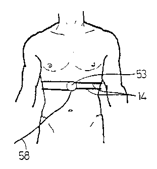
The display unit schematically shown in Fig. 6 com-
prises the housing 53 in which the electro-acoustic transdu-
cers 15, 16 are housed. One of these electro-acoustic transdu-
cers 15, 16 functions as source, the other as receiver unit.
The electro-acoustic transducers 15, 16 are connected with
each other via the elastic tube 14, which is made, for in-
stance from silicone polymers. The connection between the tube
14 and the electro-acoustic transducers 15, 16 can be made by
means of the tube connectors 54, 55 mounted in the housing.
For securing to chest or abdomen with the aid of the tube 14,
the housing can be provided with a fastening notch 56, extend-
ing for example over 180° or more over the circumference of
the housing.
As mentioned above, the electro-acoustic transducers
15, 16 may be housed in a housing. This housing may have the
form of a clasp, whereby the tube 14 is formed into a single
PCT/NL93I00273
WO 94!14374
large loop and is stretched double around the chest andjor
abdomen. This is shown in Fig. 7, whereby the tube 1~ is
stretched in a double loop around a person's chest and the
housing 53 functions as clasp. The tube 1.~ is brought over an
5 operable distance into the fastening notch 56. The connecting
lead 58 leads from the housing to the processing device 4 (not
shown).
According to a favourable embodiment the interactive
respiratory regulator is executed in the form of an automatic
10 device comprising a control program and predetermined standard
values. Dependent on the user, for example in the case of
children or patients such as stress patients, trauma patients,
one ma.y deviate from the fixed standard values, the respirato-
ry regulator exactly controls the respiration in correspon-
c~ence with the parameters (frequency, ratio, pause) incorpora-
ted in the standard values. This enables the user, without
help from a doctor or expert, to operate and use the respira-
tory regulator, which was not possible with the respiratory
regulators according to the prior art.
In Fig. 8 the ratio R, being the inhalation time
divided by the exhalation time, is plotted against the number
of respirations per minute. This gives a different picture for
different user groups. Field A, indicated by a discontinuous
line, comprises normal, healthy adults while field D, indi-
Gated by a continuous line, shows the level of respiration
achieved by people going in for sports and yoga. Individuals
with irregular respiration are found in field C, indicated by
a dot-dash line. Individuals who hyperventilate are found in
field B. For children whose chest is not yet full-grown, a
similar graph can be made. Thus the apparatus according to the
invention also allows a diagnosis to be made. In addition, the
apparatus can be used for therapeutic purposes without any
further adaptations. Apart from regulating deficient respira-
tory patterns the apparatus according to the invention was
also shown to help people who, through traumatic experiences
in the past and in spite of psychotherapy or relaxation exer-
cises, were unable to breathe in a healthy, regular manner, to
breathe calmly and controlled within 5-10 minutes. In this way
it was possible to achieve a deep relaxation much faster than
when using apparatuses according to the prior art, which has a
WO 94/14374 2 ~ ~ ,~ ~ ,~ ~ 11 PCT/NL93/00273
very favourable effect on coping with psychic traumas.