Note: Descriptions are shown in the official language in which they were submitted.
- 21 52642
HOLDER FOR PAPER TOWELS
Backqround of the Invention
Holders for rolls of paper toweling and the like,
principally mountable on a vertical wall surface or on a
horizontal surface as beneath overhanging kitchen cabinets,
normally consist of an elongate generally flat base or bar
with a pair of spaced forwardly projecting arms. The arms in
turn have lugs in facing opposition to each other which
receive the towel roll therebetween.
The arms are either rigidly fixed to the base or
pivotally mounted thereon, and at mid-distance between the
opposed longitudinal edges of the base.
In at least one instance, note U.S. Patent No. Des.
286,118, issued October 14, 1986 in the name of Gecchelin, the
base has been formed with a full length overlying shelf. This
would appear to require a mounting of the Gecchelin device
horizontally on a vertical surface.
SummarY of the Invention
The present invention comprises a holder for paper
towels and the like utilizing three separately formed
2~ 52642
substantially rigid components, preferably molded of an
appropriate synthetic resin. The components include an
elongate mounting base and a pair of end supports which
slidably engage with the base and are supported thereby upon a
mounting of the base to a support surface by appropriate
screws or the like.
The end supports, in addition to providing opposed
hubs or stub shafts for reception within the opposed ends of
the center core of a paper roll, also provide a backed shelf
extending longitudinally beyond each of the opposed ends of
the base and the supported roll.
The holder is convertible for mounting either on a
vertical surface or an overlying horizontal surface, with the
shelves, in each instance, remaining horizontal and usable.
The relationship between the elongate base and the end
supports is such that an adjustment between vertical and
horizontal mounting is effected by reorienting the base
without changing the position of the shelf-forming end
supports. The reorientation is easily achieved by a
longitudinal turning of the base end-for-end, and a transverse
rotation of the base 90 degrees. The end supports include
angled brackets which slidably engage with the opposed ends of
the base in either position thereof for locking in a slidably
2 1 52642
adjusted position by mounting screws used to secure the base
to the support surface.
Providing for the accommodation of the holder on a
vertical surface or a horizontal surface in this manner, in
addition to maintaining the shelves properly oriented, also
enables a positioning of the roll-mounting hubs, as well as
the roll itself, in the optimum position, rather than
attempting to accommodate, as in the prior art, a situation
wherein the entire holder itself must be reoriented.
lQ Other features and advantages of the invention will
become apparent from the details of the invention as
hereinafter set forth.
Brief DescriPtion of the Drawinqs
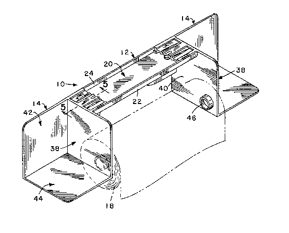
Figure 1 is a perspective view of the holder of the
invention assembled for mounting on a overlying horizontal
surface;
Figure 2 is an exploded front perspective detail of
the right end portion of the base and the bracket portion of
the corresponding end support;
Figure 3 is a rear perspective detail of the assembled
components of Figure 2;
Figure 4 is a rear perspective detail of an end
portion of the base;
`- 21 52642
Figure 5 is an enlarged cross-sectional detail taken
substantially on a plane passing along line 5-5 in Figure 1;
Figure 6 is an enlarged cross-sectional detail taken
substantially on a plane passing along line 6-6 in Figure 3;
Figure 7 is an exploded perspective view of the three
components of the invention with the base oriented for
securement to an overlying horizontal surface; and
Figure 8 is an exploded perspective view of portions
of the end supports with the base inverted relative to Figure
7 for mounting on a vertical surface.
DescriPtion of Preferred Embodiment
Referring now more specifically to the drawings, the
holder for paper towels or similar sheet material is generally
designated by reference numeral 10. The holder 10 consists of
three components, a central elongate base 12 and two shelf-
forming end supports 14. The assembled components, as
suggested in Figure 5, are retained in assembled relationship
and simultaneously fixed to a support surface by a pair of
fasteners 16, preferably screws.
As will be appreciated from the drawings, the end
supports 14 slidably engage with the opposed end portions of
the elongate base 12 and are slidably adjustable relative
21 52642
thereto and to each other for accommodating minor differences
in the width of a paper roll 18 to be supported therebetween.
The base 12, considering the orientation thereof
illustrated in Figures 1-7 for engagement with an overhead
horizontal surface, comprises an elongate planar top or
mounting panel 20. A laterally or upwardly directed flange 22
is integral with the panel 20 along the full length of the
linear outer or front edge thereof.
The top panel 20 along the longitudinal inner or rear
edge thereof, is provided with a laterally or upwardly
projecting integral edge flange 24 centrally therealong and
for a major portion of the length of the panel 20. This
flange 24 is parallel to and of equal or substantially equal
height with the outer flange 22. The rear or inner edge of
the panel 20 beyond each of the linear ends of the flange 24,
is offset toward the flange 22 and is provided with an
integral laterally or upwardly projecting flange 26 which
parallels the flange 22 and extends to the respective extreme
longitudinal end of the base 12. Each of the flanges 26 is of
a lesser height than the flanges 22 and 24. In addition, each
of the flanges 26 at the inner end thereof adjacent the
corresponding end of the elongate central flange 24, is
laterally turned as at 28, to define a longitudinally facing
abutment surface. The offset end portions of the inner or
~ 2 1 52642
rear edge of the panel 20, and the integral flanges 26
thereof, define a pair of rearwardly directed recesses 30, the
purpose of which will be described subsequently.
The top mounting panel 20 is provided with a pair of
spaced, laterally upwardly offset, apertured bosses 32
gene~rally along the longitudinal center line thereof and
generally transversely aligned with the turned ends 28 of the
flanges 26. As best illustrated in Figure S, these bosses 32
are adapted to receive the driven fasteners 18 used to mount
the paper towel holder 10. The recesses defined by the bosses
will conveniently receive and at least partially conceal the
heads of the fasteners.
The base 12 is completed by a pair of rear or inner
stabilizing panels 34, each integral with and forming a
coplanar continuation of a rear flange 26. The panels 34, for
approximately the length of the respective flanges 26, are of
equal transverse width with the transverse width of the end
portions of the mounting panel 20. The panels 34 extend
longitudinally inward of the respective turned inner ends 28
of the flanges 26 and are integral with the undersurface of
the panel 20 coplanar with the end portion flanges 26 and
laterally inward of the plane of the central flange 24. The
panels 34 terminate in longitudinally spaced relation to each
2 1 52642
other and, as at 36, have the lower and inner edges thereof
merging along an arc.
The end units or supports 14 are mirror images of each
other, and regardless of whether the holder is mounted on a
vertical surface or a horizontal surface, the end supports 14
remain in the vertical orientation illustrated in the
drawings. A change in the mounted position of the holder 10
is accomplished solely through a reorientation of the base 12.
Each of the end supports 14 includes an upstanding
planar side wall or member 38 with an inwardly directed
surface 40 in facing relation to the inner surface 40 of the
second end support wall 38. A planar back or rear wall or
member 42, of equal height with each side wall 38, is
integrally formed with the rear edge of the wall 38 and
extends perpendicularly outward relative thereto. Finally, a
planar horizontal, bottom or support wall or member 44, along
right-angularly related edges thereof, is integrally joined
with and along the lower edges of the side and back walls of
each of the end supports 14 with each bottom wall 44 supported
by the associated side and back walls to define a shelf.
In order to support a roll 18 of paper or the like, a
pair of mounting hubs or stub shafts 46 are integrally formed,
one on and inwardly projecting from the inner surface 40 of
each end wall 38 adjacent the lower forward corner thereof.
2 1 52642
These hubs 46 are in facing relation to each other and sized
for accommodation within the opposed open ends of the core of
a roll 18 in a manner which allows for a rolling of the roll
for selected discharge of the paper or sheet material.
Each of the end supports mounts to the corresponding
end portion of the base 12 by means of a bracket 48 rigid with
the corresponding side wall 38 and projecting inwardly from
the inner surface 40 at the upper rear corner portion thereof.
The bracket 48, in each instance, comprises a pair of right-
angularly related top and rear panels 50 and 52. These
bracket panels 50 and 52 are integrally molded with the
corresponding side wall 38 and project perpendicularly inward
from the inner surface 40 thereof. The top and rear bracket
panels 50 and 52 of each end support 14 extend partially along
the respective upper and rear edges of the corresponding end
wall 38 for a length thereof approximately corresponding to
the width of the end portions of the base 12 which are to
engage therewith.
The bracket panels S0 and 52 are of the same
configuration and have outer faces respectively coplanar withthe upper edge of the corresponding side wall 38 and the rear
surface of the corresponding rear wall 42. Each of the panels
50 and 52 of each bracket 48 extends from a central corner rib
54 of substantially square cross-section and common to both
2 1 52642
panels. The outer edge of each panel 50 and 52, parallel to
the corner rib 54, is defined by a full length flange 56. The
outer surface of each panel 50 and 52, centrally between the
corner rib 54 and the corresponding outer flange 56, includes
a relatively wide intermediate rib 58 with a planar upper
surface, whereby upwardly directed recesses 60 and 62 are
formed respectively between the corner rib 54 and the
intermediate rib 58, and the outer edge flange 56 and the
intermediate rib 58. Each of these recesses in turn includes
an upwardly projecting longitudinally extending reinforcing
rib 64 tapering from a maximum height and width at the free
edge of the respective panel to a minimum height adjacent the
fixed end of the bracket panel.
Each intermediate rib 58 of each of the panels 50 and
52 of each bracket 14 includes a central elongate slot or
notch 66 extending inward from the free panel edge remote from
the corresponding side wall 38 for selective alignment with a
corresponding screw-accommodating boss 32 of the base 12, and
in particular with the central aperture within the boss.
The inner face of each of the bracket panels 50 and 52
includes elongate reinforcing ribs 68 transversely aligned
with corresponding ribs 64 on the outer face and of a constant
size corresponding to the outer ends of the ribs 64 along the
full length of the panel inner face.
2 ~ 52642
Finally, each of the bracket panels 50 and 52 includes
a retaining flange 70 extending along the full length of the
inner face of the panel inward from the free edge thereof.
The retaining flange 70, also in the nature of an elongate
rib, is laterally inwardly spaced from the corner rib 54 or
adjacent perpendicular panel and defines a receiving groove 72
therebetween. Noting Figure 5, the two retaining flanges 70
of these adjacent panels have the free outer edges thereof so
spaced as to slidably receive the elongate end portion flanges
26 of the base 12 upon an assembly of the holder as shall be
described subsequently.
In assembling the holder 10 for mounting to a
horizontal overhead support surface, the base 12 is oriented
with the panel 20 horizontal and with the panels 34 to the
rear thereof and depending perpendicular therefrom. The end
supports 14 are positioned to the opposite ends of the base 12
with the bottom walls 44 horizontal and with the respective
side and rear walls extending vertical therefrom. The side
walls are in facing relation and the hubs 46 thereon are
aligned.
Noting Figures 2, 3 and 6 in particular, the brackets
48 are slidably and telescopically engaged with the opposed
end portions of the base 12. The top or horizontal panel of
each bracket 48 overlies the corresponding end portion of the
21 52642
base top panel 20 with the base front flange 22 receiving the
bracket panel flange 56 immediately inward thereof. The rear
flange 26 of each end portion of the base 12 is slidably
received below the corresponding top bracket panel 50 and
within the retaining groove 72 between the rear bracket panel
52 and the forwardly spaced retaining flange 70 depending from
the top panel 50 of the respective bracket.
Each depending rear bracket panel 52 is positioned
behind and concealed by the corresponding rear base panel 34.
Further, when each end portion of the base 12 is fully
telescopically engaged with the corresponding bracket 48, the
outer free end of the corner rib 54 of the bracket will engage
against the turned end portion 28 of the adjacent flange 26.
The depth of the rear recess 30 at each end portion of the
base 12 is sufficient to accommodate the thickness of the rear
bracket panel 52 for a general coplanar alignment of the~--
rearmost faces of the brackets 48, end supports 14 and base
12. The mounted paper roll 18 will be easily accessible in
that the mounting hubs or stub shafts 46 are positioned
zO substantially forward of the rear face of the holder and an
appreciable distance below the top plane of the holder.
It will also be noted that each of the screw-receiving
bosses 32 aligns beneath the corresponding bracket panel slot
66. Thus, upon a mounting of the holder utilizing upwardly
- 2 1 52642
driven fasteners, the opposed brackets 48 will be effectively
clamped between the upwardly fixed base 12 and an overlying
support surface. The elongate slot in the two horizontal
engaged base panels 50 allow, in an obvious manner, a slight
degree of longitudinal adjustment between the end supports 14.
It is contemplated that sufficient inherent flexible
resiliency reside in the holder structure, and in particular
the end supports 14 and the facing side walls 38 thereof, to
allow for a mounting and removal of the roll 18. Also, as
will be recognized, the conventional paper roll itself
includes a degree of resilient softness which will facilitate
mounting and removal. Should sheet material of a particularly
rigid nature be involved, mounting can always be effected by a
slight loosening of the fasteners or screws to allow for an
outward shifting of the end supports 14 and a subsequent
inward re-engagement after the roll is positioned. This~would
not normally be necessary.
Referring now particularly to Figure 8, should it be
desirable to mount the holder on a vertical wall surface, the
base 12 can be turned end-for-end and rotated 90 degrees to
position the coplanar panels 34 horizontally, and the prior
top mounting panel 20 vertically in the nature of a rear
mounting panel.
- 2 t ~2642
After a repositioning of the base 12, engagement of
the end portions of the base 12 with the brackets 48 is much
as described above. The now horizontal panels 34 immediately
underlie the bracket top panels 50 and with the end portions
of the mounting panel 20 engaging immediately inward of the
vertical bracket panels 52. This relationship can best be
appreciated by visualizing the cross-section of Figure 6
rotated 90 degrees toward the left. In this position, the
bosses 32 are positioned vertically and aligned with the slots
or notches 66 in the vertical rear panel 52 of the brackets 48
for a mounting of the holder on a vertical surface.
The foregoing is illustrative of the preferred
embodiment of the invention, and as other embodiments
incorporating the inventive features of the invention may
occur to those skilled in the art, the disclosed embodimént is
not to be considered as a limitation on the scope of the~
invention. Rather, the invention is only to be limited by the
scope of the claims following hereinafter.