Note: Descriptions are shown in the official language in which they were submitted.
212681
SLICKLINE CONVEYED WELLBORE SEISMIC RECEIVER
The present invention is related to the field of geophysical exploration. More
specifically, the present invention is related to the use of a seismic
receiver in a
wellbore, in particular for conducting a seismic survey while the wellbore is
being
drilled.
A seismic receiver typically is deployed in a wellbore for determining the
response of the earth to seismic energy in the vicinity of the wellbore, which
enables
determination of certain characteristics of the earth in the vicinity of the
wellbore such
as geological structure, and the location of changes in the material
properties of the earth
which may naturally occur.
The various uses of a seismic receiver deployed in a wellbore, also known as a
borehole seismic receiver, are known in the art. For example, "Vertical
Seismic
Profiling", by Bob A. Hardage, Geophysical Press, London, 1985, describes
typical
applications for the use of a borehole seismic receiver.
One of the reasons for using a borehole seismic receiver is for matching
various
depths within the earth penetrated by the wellbore to specific travel times of
seismic
energy generated at the earth's surface. In relatively unexplored areas,
geophysical
surveys are typically conducted entirely at the earth's surface. Being able to
determine
the time for seismic energy to travel to a particular depth within the earth,
using a
surface seismic survey, depends on a portion of the seismic energy generated
at the
earth's surface for the survey being reflected from a zone in the earth having
an.acoustic
impedance mismatch. Impedance mismatches, known as reflectors, typically occur
at
boundaries of changes in material composition or material properties of the
earth.
Reflectors are of particular interest for identifying possible exploration
targets within the
earth. In order to calculate the depth to a particular exploration target in
the earth,
where the seismic travel time is determined by the presence of a reflector in
the surface
seismic survey, it is necessary to determine the velocity of the seismic
energy through
the earth. The velocity of the seismic energy through the earth is strongly
related to the
composition and material properties of the earth. The material properties of
the earth
may vary widely within different earth formations within the depth range
traversed by
~1~26~1
2
the wellbore.
It is not possible to explicitly determine velocity of the formations solely
from
the surface seismic survey, therefore, when a wellbore is drilled in a
relatively
unexplored area, a borehole seismic receiver is typically used to make
measurements
which are used to determine the velocity of the seismic energy within the
earth.
Determining the velocity of the formations while the wellbore is being
drilled,
rather than after the drilling is completed, can be particularly valuable in
certain
instances. For example, some wellbores are drilled directionally to the
exploration
target because the target is located at a horizontally displaced location from
the location
of the wellbore at the earth's surface. If the target has been selected only
on the basis
of seismic travel time to a reflector, then the depth to the target may not be
precisely
determinable without knowledge of the velocity of the formations from the
earth's
surface to the depth of the target. This could cause the planned wellbore
trajectory to
miss the target entirely. Periodic use of a wellbore seismic receiver during
drilling, in
conjunction with a seismic energy source deployed at the earth's surface
directly above
the position of the wellbore seismic receiver, enables measurement of seismic
energy
travel time to the depth of the seismic receiver deployed in the wellbore. The
measurement of seismic travel times to various depths enables calibration of
the surface
seismic survey travel time in depth, thereby increasing the probability that
the target will
be penetrated by the wellbore.
Certain reflectors observed on the surface seismic survey are of particular
concern in drilling the wellbore. For example, "Abnormal Formation Pressure",
by
Walter Fertl, Elsevier Publishing, Amsterdam, 1976, describes reflectors which
sometimes correlate to the presence of significant changes in the gradient of
fluid
pressure contained within some formations. Knowledge of the precise depth of
the
reflector could prevent drilling problems which might result from an
unintended
penetration by the wellbore of a formation containing fluid pressure with a
significantly
different gradient than the gradient otherwise expected in the vicinity of the
wellbore.
The use of a borehole seismic receiver to calibrate seismic travel time to the
wellbore
~~~2sm
3
depth could enable more precise determination of the depth of the reflector,
which could
prevent unintended penetration of the formation having abnormal fluid
pressure.
It is also known in the art to use borehole seismic receivers for generating
seismic
reflection sections in an area within about 1000 feet around the wellbore.
Seismic
energy from the seismic energy source also travels deeper than the receiver in
the
wellbore, and the seismic energy can be reflected by zones having acoustic
impedance
mismatch, just as with a surface seismic section. The reflection energy can be
identified
by appropriate processing of a recording of the energy detected by the
receiver. The
identified reflection energy can be displayed in a form for comparing the
borehole
seismic survey with the surface seismic survey.
It is difficult to use the borehole seismic receivers known in the art, while
the
wellbore is being drilled. Each time the borehole seismic receiver is to be
run in the
wellbore, drilling the wellbore must stop, and a drillpipe, which is used to
operate a
drilling bit, must be removed from the wellbore. The drillpipe is formed from
sections
each having a length of thirty to ninety feet. The sections are joined by
threaded
connections which must be uncoupled each time the drillpipe is removed from
the
wellbore. Further, the borehole seismic receiver must be run in the wellbore
on an
electrical cable, or wireline, and a clamping mechanism, which forms part of
the
borehole seismic receiver and forces the receiver into contact with the
wellbore wall, is
deployed to enable good acoustic coupling from the wellbore wall to the
borehole
seismic receiver. There is a significant risk of the borehole seismic receiver
becoming
stuck in the wellbore. Retrieving the borehole seismic receiver when it is
stuck in the
wellbore is particularly difficult because the wireline obstructs the process
of retrieval
of objects stuck in the wellbore.
It is an object of the present invention to provide a borehole seismic
receiver
which can be deployed in a wellbore without removing the drillpipe from the
wellbore.
It is a further object of the present invention to provide a borehole seismic
receiver which can be deployed without the use of an electric wireline.
CA 02152681 2003-12-05
4
In accordance with the invention an apparatus for recording a geophysical
survey in a wellbore penetrating an earth formation is provided. The apparatus
comprises a seismic receiver, adapted for traversing the wellbore, and
comprising
at least one transducer (e.g. comprising a hydrophone pressure detector, a
s geophone, an accelerometer or any other suitable transducer means for a
desired
application), a power source and a signal processing and recording unit
disposed
within the receiver. The signal processing and recording unit is programmed to
generate a recording of an electrical signal generated by a transducer as a
result
of detecting seismic energy. A surface control unit is connected to a seismic
1 o energy source (e.g. an air gun array, dynamite, a vibrator unit or any
other suitable
source of seismic energy for a desired application) and is synchronized with
the
signal processing and recording unit to activate the seismic energy source at
predetermined time intervals corresponding to time intervals at which the
signal
processing and recording unit generates the recording. The surface control
unit is
15 adapted to record an acoustic signature of the seismic energy source. The
signal
processing and recording unit comprises: an analog signal processor connected
to a transducer, the processor including an amplifier and a filter; a first
analog-to-
digital converter connected to the analog signal processor; a digital signal
processor connected to the first analog-to-digital converter; a first timer-
controller
2 o connected to the analog to digital converter, the first timer-controller
programmed
to activate the first analog-to-digital converter at predetermined time
intervals
corresponding to the predetermined time intervals at which the seismic energy
source is activated; a first clock connected to the first timer-controller, a
digital
memory connected to the digital signal processor and to the first timer-
controller;
2 s and, a communications port connected to the first digital signal processor
wherein
the recording is transferred from the digital memory to the surface control
unit and
wherein the signal processing and recording unit is synchronized to the
surface
control unit.
Preferably the surface control unit of the apparatus further comprises a
3 o source controller connected to the seismic energy source, a second timer-
controller, connected to the source controller, programmed to activate the
source
controller at predetermined time intervals, a second clock connected to the
second
CA 02152681 2003-12-05
4a
timer-controller, a communications bus connected to the second timer-
controller,
a near-field sensor (e.g. a hydrophone pressure detector, at least one
accelerometer, at least one geophone or any other such suitable means for a
desired application), a second analog-to-digital converter connected to the
near-
s field sensor for digitizing the acoustic signature, and a computer connected
to the
second timer-controller and to the second analog-to-digital converter, wherein
the
recording is downloaded into the computer through the communications bus and
the recording is correlated to the acoustic signature of the seismic energy
source
measured by the near-field sensor.
1 o Also in accordance with the invention there is provided a method for
conducting a borehole geophysical survey in a wellbore penetrating an earth
formation. A borehole geophone receiver, comprising a signal processing and
recording unit, is connected to a surface control unit with a communications
bus
and a recording unit, and a first clock disposed with the surface control unit
is
15 synchronized with a second clock disposed with the receiver. The borehole
geophone receiver is lowered into the wellbore. A source controller disposed
within
the surface control unit is activated. At least one activation of a seismic
energy
source disposed at the earth's surface is observed. The receiver is removed
from
the wellbore. The receiver is reconnected to the surface control unit by the
2 o communications bus and a recording of a signal detected as a result of
seismic
energy from the seismic energy source is downloaded. The recording is
correlated
to an acoustic signature of the seismic energy source recorded by the surface
control unit, thereby determining the travel time of the seismic energy from
the
seismic energy source to the receiver disposed with the wellborn.
25 Figure 1 shows the invention as typically used in a marine borehole
geophysical survey, by deployment within a drillpipe by a slickline.
Figure 2 shows in greater detail the components of the invention and the
method of landing in the drillpipe.
Figure 3 shows a block diagram of the functional components of a borehole
3 0 receiver.
212681
Figure 4 shows a block diagram of the functional components of a surface
control
system.
Figure 5 shows an alternative embodiment of the receiver comprising
accelerometer sensors.
Figure 6 shows an alternative embodiment of the receiver comprising geophone
sensors.
Figure 1 shows the invention as it is typically used in a marine borehole
geophysical survey. From a drilling platform, or rig 22, a borehole seismic
receiver 2
is lowered into a drillpipe 9 in a wellbore 10 by means of a winch 12 which
spools a
single strand steel cable 8, known as slickline. Slickline 8 is typically used
when
servicing tools, which neither need surface supplied electrical power nor
transmit signals
to the surface by wire or cable, are conveyed into the wellbore 10. The winch
12 is
typically referred to as a slickline unit. At the end of the drillpipe 9 is a
bottom hole
assembly 15, or BHA, comprising drill collars 11, a muleshoe sub 4, and a
drill bit 6.
The BHA 15 is normally used during the drilling of the wellbore 10. When a
borehole
seismic survey is recorded, the drilling process stops, but the drillpipe 9
and BHA 15
remain in the same configuration as during the active drilling of the wellbore
10.
The muleshoe sub 4 is typically included in the BHA 15 to provide a landing
for
directional surveying instruments such as magnetic multishots. The receiver 2
can land
in the muleshoe sub 4, which reduces the possibility of inducing noise in the
receiver as
a result of movement of the receiver while a survey is being recorded.
A seismic energy source 16, which in this embodiment is an air gun array, is
towed by a boat 20. The source 16 is positioned as closely as possible to
vertically
above the position in the earth of the receiver 2 in the wellbore 10. The
source can be
controlled by radio signals 24A and 24B when the invention is used to conduct
a marine
borehole geophysical survey. The radio signals 24A and 24B are generated by a
surface
control unit 14 located on the rig 22. In a land-based borehole geophysical
survey, the
source 16 can be directly connected to the surface control unit 14. When the
source 16
is activated, seismic energy waves 18 travel through the earth to the receiver
2 where
21~26R1
6
they are detected and recorded.
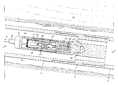
The construction of the receiver 2 can be better understood by examining
Figure
2. The receiver 2 is enclosed in a housing 30 adapted to withstand the
environment of
the wellbore 10, which can have temperatures exceeding 350 degrees Fahrenheit
and
pressures exceeding 20,000 psi. The housing 30 is attached to the slickline 8
by a cable
head 32 affixed to the top of the housing 30.
The housing 30 is lowered into the drill collars 11 until a key 36 at the
bottom
of the housing 30 lands in a matching slot 37 in the muleshoe sub 4. The
slickline unit
(shown as number 12 in Figure 1) includes equipment for indicating to the
operator that
the receiver has landed in the muleshoe sub 4.
In the wall of the housing 30 is a chamber 38 in which is located an acoustic
transducer 44, which in this embodiment is a piezoelectric hydrophone. The
chamber
38 is in fluid communication with the interior of the drill collars 11. The
transducer 44
is enclosed in a reservoir 41 which can be composed of a flexible elastomeric
material.
The reservoir is affixed to the housing 30 inside the chamber 38. The
reservoir 41 is
completely filled with a substantially non-compressible fluid such as
hydraulic oil. The
reservoir 41 is covered by a metal screen 40, which enables fluid
communication with
the drillpipe (shown as number 9 in Figure 1), but protects the reservoir 41
from
mechanically induced damage.
21~26~1
The housing 30 also comprises an enclosure 47 for a signal processing and
recording system 34. The enclosure 47 is pressure sealed from the chamber 38
by feed
through connectors 46 which make electrical connections from the recording
system 34
to the transducer 44. A portion of the recording system 34 is contained inside
a Dewar
flask 49 located inside the enclosure. The flask 49 provides a substantially
constant
temperature to a portion of the recording system 34. Maintaining constant
temperature
to the portion of the recording system 34 is desirable for enabling a high
degree of
precision of timing of data recorded by the recording system 34.
The seismic energy waves 18 emitted by the source (shown as 16 in Figure 1)
travel through the earth until they contact the wall of the wellbore 10,
whereupon the
waves 18 are transmitted through a fluid 42 filling the drill collars 11 and
the wellbore
10. The waves 18 passing through the fluid 42 behave as compressions and
rarefactions
of the fluid 42. The waves 18 finally travel through to the transducer 44 by
means of
alternately compressing and rarefying the fluid filling the reservoir 41. The
transducer
44 converts the waves 18 into a time-varying electrical voltage which is
conveyed
through the feed through connectors 46 to the recording system 34.
Figure 3 shows the functional components of the recording system (shown as
number 34 in Figure 2) located within the receiver (shown as number 2 in
Figure 1).
The recording system 34 is electrically powered by a battery 62, which in this
embodiment can be a lithium battery. The time varying electrical voltage
generated by
the transducer 44 as it converts the received seismic energy waves (shown as
number 18
in Figure 2) is conducted to an analog signal processor unit 52. The analog
processor
52 provides amplification of the signal from the transducer 44, which in this
embodiment
has a gain factor of 1000 or 60 dB. The analog processor 52 also provides
filtering to
remove components of the signal which have a frequency above the maximum
expected
frequency content of the seismic energy waves 18. The amplified, filtered
signal is then
fed to a first analog to digital converter 54, or first ADC, which in this
embodiment can
be a Crystal Products Company model number CS~336. The first ADC 54 in this
embodiment also has a signal processing function in which the analog input
from the
~1~26R1
8
analog processor 52 is significantly oversampled. Oversampling enables use of
analog
filtering on the analog processor 52 with significantly less severe "roll-
off", or decrease
in output amplitude with frequency, than would otherwise be required to
prevent
"abasing" of the signal. The signal is converted by the first ADC 54 into a
series of
binary numbers, also called a digitized signal. The operation of the first ADC
54 is
timed by a first timer-controller 61 which in this embodiment can be an Intel
Corp.
model number EB186 processor. The first timer-controller 61 is programmed to
activate
the first ADC 54 only at predetermined time intervals corresponding to the
time of
activation of the seismic energy source (shown as number 16 in Figure 1),
commencing
after a predetermined time delay to enable the receiver 2 to reach the
deployment depth
in the wellbore 10 without making unnecessary recordings. The time delay can
be
selectable by the operator. Time information is provided to the first timer-
controller 61
by a first clock 60, which in this embodiment can be a Piezoelectric Corp.
model
number 692004. After the first ADC 54 converts a signal from the transducer 44
into
a digitized signal, a digital signal processor 56, or DSP, digitally filters
the signal and
routes the digitized signal into a digital memory 58. The DSP 56 also measures
the
average amplitude of the signal level of an individual digitized signal. If
the average
amplitude of the signal exceeds a predetermined fraction, which in this
embodiment is
50 percent, of the full-scale amplitude capacity of the first ADC 54, the
digitized signal
is rejected and is not transferred to the memory 58. Rejection of excessive
average
amplitude signals reduces the possibility that signals corrupted by noise from
motion of
the receiver 2 will be recorded. The value of 50 percent of full-scale was
selected as an
arbitrary initial value. Extended field experience may enable refinement of
the value of
50 percent.
At the time the digitized signal is transferred to the memory 58, the time of
recording of the specific digitized signal is also transmitted from the first
timer-controller
61 to the memory 58.
The first clock 60 is housed in the flask (shown as 49 in Figure 2). The flask
49
maintains a substantially constant temperature around the first clock 60
during the
21~26~1
9
survey, because the first clock 60 can change frequency to some degree with
temperature
change. Maintaining substantially constant temperature at the first clock 60
increases
the accuracy of the timing data stored in the memory 58 and operating the
first timer-
controller 61.
Digitized signals with their associated time information which are stored in
the
memory 58, can be later accessed through a communications port 64A. After a
survey
is recorded, the receiver 2 is brought to the earth's surface and the
communications port
64A is connected to the surface control unit (shown as 14 in Figure 1) by a
cable (not
shown).
Figure 4 shows the functional components of the surface control unit (shown as
14 in Figure 1). A second clock 68, which can be the same type as the first
clock
(shown as 60 in Figure 3), provides timing information to a second timer-
controller 71.
The second timer-controller 71 can be the same type as the first timer-
controller 61. The
second timer-controller 71 transmits control signals to a source controller
66, at time
intervals programmed to match the time intervals in which the first timer
controller
(shown as 61 in Figure 3) is programmed to activate the ADC (shown as 54 in
Figure
3) in the receiver 2. The source controller 66 activates the seismic energy
source 16 at
predetermined intervals during the survey. The source controller 66 can be
directly
connected to the source 16, or can transmit activating signals by radio signal
(shown as
24A and 24B in Figure 1). The synchronization of the first ADC 54 operation
with the
source controller 66 operation both conserves battery (shown as 62 in Figure
3) power
in the receiver 2 and minimizes the amount of data stored in the memory (shown
as 58
in Figure 3) in the receiver 2.
A near-field sensor 73, which in this embodiment is a hydrophone positioned
within one-half wavelength of the energy from the source 16, or about 25 feet,
is used
to record the acoustic signature of the energy of the source 16. The near-
field sensor 73
output is routed to a second ADC 70, which can be the same type as the first
ADC 54.
The second ADC 70 is timed to digitize the sensor 73 output on receipt of
command
signals from the second timer-controller 71, which are timed at substantially
the same
2152681
time intervals as the first timer-controller 61 is programmed to activate the
first ADC
54. The output from the second ADC 70 is routed to a computer 74, which in
this
embodiment can be a workstation such as a SUN Microsystems Corp. model SPARC
10,
for later processing.
A communications bus 64B forms part of the second timer-controller 71. The
bus 64B is connected to the communications port (64A in Figure 3) in the
receiver 2 by
the cable (not shown) prior to the first survey being run, and again when the
receiver 2
is brought to the surface at the conclusion of a survey. Data are transferred
from the
memory 58 in the receiver 2 by the port 64A to the bus 64B, whereupon the data
are
transferred to the computer 74 for later processing.
The other purpose for connecting the bus 64B to the port 64A is for the
synchronization of the first clock (60 in Figure 3) and the second clock 68.
Timing data
associated with digitized signals recorded in the receiver 2 must be related
accurately to
the time of activation of the source 16 in order to determine the travel time
of the energy
waves (shown as 18 in Figure 1) from the source 16 to the receiver 2.
Synchronization
of the first clock 60 and the second clock 68 before the receiver 2 is run in
the wellbore
10, and subsequent comparison of the time measured by the first clock 60 and
the second
clock 68 after the survey is completed to adjust for any time drift between
the first clock
60 and the second clock 68, enables precise determination of the time of
recording of
signals in the receiver 2 relative to activation of the source 16. By
determining the
precise time of events recorded by the receiver 2 and comparing the time to
the timing
of activation of the source 16, the travel time of the seismic energy waves 18
from the
earth's surface to the receiver 2 in the wellbore 10 can be determined.
Data read from the memory 58 when the receiver 2 is brought to the surface are
routed from the bus 64B to the computer 74 for processing with the recordings
of the
source 16 acoustic signature made during the survey. The recordings can be
processed
by methods known in the art. For example a VSP survey processing program such
as
one used by Atlas Wireline Services under the trade name SEISLINK-X, can form
part
of the programming of the computer 74 to enable processing of the survey
records from
2152681
11
the receiver 2 into a VSP survey.
Referring now to Figure 5, a different type of transducer can be examined. The
chamber 38 in the housing 30, which in the first embodiment was open to the
wellbore
10, in the second embodiment is enclosed and pressure sealed as is the rest of
the interior
of the housing 30. A frame 96 comprising three flat surfaces 96A, 96B, 96C
which are
orthogonal to each other, is rigidly mounted inside the chamber 38. An
accelerometer
90, 92, and 94, for each of the three orthogonal axes, with one axis parallel
to the
longitudinal axis of the housing 30, is mounted on each of the flat surfaces
96A, 96B,
96C on the frame 96. The accelerometers 90, 92, 94 respond to change in
velocity of
the housing 30 along the axis aligned with each accelerometer 90, 92, 94.
Signal
processing is substantially the same as in the first embodiment, with the
exception that
there must be a separate signal channel in the recording system 34 for each
accelerometer 90, 92, 94.
Figure 6 shows an alternative embodiment using three geophones 100, 102, 104,
mounted on gimballed bearings 106 attached to a frame 98. The gimballed
bearings
106, enable the geophones 100, 102, 104, to orient by gravity, enabling the
geophones
100, 102, 104 to remain in alignment with the propagation direction of the
seismic
energy waves 18. The frame 98 is rigidly mounted inside the housing 30. As in
the
second embodiment, the recording system 34 must have one signal channel for
each
geophone 100, 102, 104.