Note: Descriptions are shown in the official language in which they were submitted.
21~3359
-
Title of the Invention:
,. SLIDE MOUNT
BackgrQund of the Invention:
The present invention relates to a slide mount and,
particularly, to a slide mount onto which can be correctly
fitted a film that is cut into individual screens.
Description of the Prior Art:
A conventional slide mount will ~e described with
reference to Fig. 6 wherein reference numeral 1 denotes a slide
mount which is made of, for example, a plastic material. The
slide mount 1 is constituted by a mount 2 and a cove-r 3, and the
mount 2 is provided with a film-placing portion 4 which has a
size nearly equal to that of a screen and further has a step
with respect to the surface of the mount 2. At the center of
the film-placing portion is opened a window 5. Furthermore,
recessed portions 6, 6, --- are formed in the periphery of the
film-placing portion 4, and the outer peripheries of the
recessed portions 6, 6, --- are formed in a protruding manner.
A window 7 is formed in the cover 3, and protruded portions 8,
8, --- are provided on the periphery of the window 7. By
fitting the protruded portions 8, 8, --- into the recessed
_ portions 6, 6,,--- of the mount 2, the mount 2 and the cover 3
are fi~rmly fitted together; i.e., the window 5 and the window 7
are superposed one upon the other to form the slide mount 1.
The film 9 that is cut into a unit of screen is placed
on the film-placing portion 4 and, then, the mount 2.and the
cover 3 are fitted together so that the film 9 is fitted onto
the slide mount 1.
In the conventional slide mount, the size of the film-
placing portion in the direction of width is set to be in
aqreement with a specified value of the commercially available
film, i.e., 35 mm. Therefore, the film that is cut into a screen
is correctly placed in position in the direction of width
thereof due to the step formed in the film-placing portion and
the outer peripheries of the recessed portions. On the other
21S~35~
'
hand, the film is cut by hand along the gap portions among the
screen~ by using a pair o~ scissors. It is therefore difficult
to cut the film into a predetermined size in the lengthwise
direction thereof. Therefore, the ~ilm-placing portion in the
lenqthwise direction thereof has been set to a size which is
larger than the size of a screen. Accordingly, the film that is
inserted in the slide mount has a margin in the lengthwise
direction and may undergo a deviation in position.
Moreover, if the window in the slide mount has a size
equal to the size of the screen of the film, then, the end of
the film becomes in short of contact with the window when the
size of the film is short in the lengthwise direction thereof,
causing light to leak. If the size of the window is selected to
be smaller than the size of the screen in order to solve the
above defect, on the other hand, there arouses another problem
in that the window and the end of the screen are superposed
causing_the screen to be partly missing.
Thus, there arouses a technical problem in regard to
correctly and easily fitting a screen of film onto the slide
mount without causing the screen to be missing. The object of
the present invention is to solve this problem.
Summary of the Invention:
_ The present invention was proposed in order to achieve
the above obgéct, and provides a slide mount for pro~ecting a
slide film one screen by one screen by using a slide device,
wherein said slide mount is constituted by a mount and a cover,
windows are formed at the central portions of the mount and the
cover, respectively, a film-placing portion is formed
surrounding the window of the mount, positioning pins are
studded at four corners of said film-placing portion so as to be
corresponded to engaging holes in both side portions of the
film, positioning holes are perforated at positions opposed to
said positioning pins, and the positioning holes are fitted to
the positioning pins, so that the mount and the cover are fitted
together, and further provides a slide mount in which the
windows formed in said mount and in said cover are larger than
~_ 3 .~ ~ 5 3 ~ ~ ~
the size of the screen of said film.
According to the invention, windows are formed at
the central portions of the mount and the cover,
respectively, and the film-placing portion is formed
surrounding the window of the mount. Here, the film to be
fitted onto the slide mount has holes perforated in both
side portions thereof in an opposing manner maintaining an
equal distance. A photograph is taken in a manner that the
pairs of holes come into agreement with gap portions among
the screens, and the gap portions at both ends of the
screen of the film are cut; i.e., pairs of holes are cut
starting from the central portions thereof, and engaging
holes are formed at both ends of the film.
The film-placing portion of the mount is disposed
being upwardly faced and the film cut into a screen is
placed on the film-placing portion. Then, the film is
placed with its central portion being curved in a convexed
manner and with its both end portions being in contact with
the film-placing portion. The film is then downwardly
pushed by bringing the cover into contact therewith from
the upper direction. The convexed central portion of the
film is pressed onto the film-placing portion and is
further extended in the lengthwise direction, so that
engaging holes at both end portions of the film come into
engagement with the positioning pins. Then, by bringing
the positioning holes in the cover into engagement with the
positioning pins, the film is correctly fitted onto the
slide mount.
More specifically, the windows formed in the
mount and in the cover have a size larger than the size of
the screen of the film and, besides, the screen of the film
is correctly disposed at the same position of the slide
mount. Therefore, the screen of the film is fitted inside
the windows without being superimposed on the windows.
Therefore, in accordance with the present
invention, there is provided a slide mount for use with a
slide device for projecting a slide film one screen by one
screen comprising a mount and a cover, windows formed at
3a ~ 5 ~
,_
central portions of the mount and the cover, respectively,
a film-placing portion formed surrounding the window of the
mount, positioning pins provided at four corners of said
film-placing portion so as to be corresponded to engaging
holes in both side portions of the film, positioning holes
defined at positions opposed to said positioning pins, the
positioning holes being adapted to be engaged with the
positioning pins so as to couple the mount and the cover
together.
Brief Description of the Drawings:
Fig. 1 illustrates an embodiment of the present
invention, wherein Fig. l(a) is a plan view of a mount and
Fig. l(b) is a plan view of a cover:
215~3~9
Fig. 2 is a plan view showing the shape of a film;
, - Fig. 3 is a plan view showing the shape of the film
cut into a screen; .
Fig. 4 is a perspective view illustrating the state
where the film is being ~itted onto a slide mount;
Fig. 5 is a plan view illustrating the state where the
film is fitted onto the slide mount; and
Fig. 6 is a plan view illustrating a prior art.
Detailed Description of Preferred Embodiments:
An embodiment of the present invention will now be
described in detail with reference to Figs. 1 to 5. Figs. l(a)
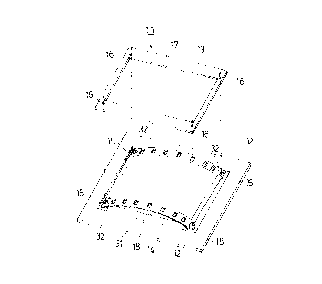
and ltb) illustrate a slide mount 11 which is constituted by a
mount 12 and a cover 13. Referring to ~ig. l(a), a film-placing
portion 14 is formed at the center of the mount 12, and is
forming a step which is equal to, or deeper than, the sum of the
thickness of the film and the thickness of the cover 13 from the
surface of the mount 12. Positioning pins 15, 15, --- are
studded at four corners of the film-placing portion 14, i.e., at
positions corresponding to engaging holes in both side portions
of the film that will be described later. As shown in Fig.
l(b), furthermore, positioning holes 16, 16, --- are perforated
in the cover 13 at positions where they will be brought into
enqaqement with the positioninq pins 15, 15, ---. Moreover,
windows 17 and 18 are opened in the mount 12 and in the cover
13, the windows 17 and 18 being arranged on the inside of the
positioning pins lS, 15, --- and the positioning holes 16, 16, -
_ _ .
Fig. 2 illustrates a film 21 which is obtained bydeveloping a positive film for slide. The film 21 has a width
of ~5 mm, and holes 22, 22, --- are perforated in an opposing
manner in the side portions of the film 21.
In the film 21 are photographed screens 23, 23, ---
which are isolated in the lengthwise direction by gap portions
24, 24, ---. The gap portions 24, 24, --- have been set in
advance at the time of taking photographs so as to be positioned
between~the holes 22a, 22a, --- that are formed in an opposing
21~33~9
manner. Therefore, the center lines of the gap portions 24, 24,
--- are in agreement with lines connecting the centers of the
holes 22a, 22a, ---. ,
By cutting the gap portions 24, 24, --- at both ends
of the screen 23 of the film 21 and cutting the holes 22a, 22a,
--- in both side portions using a pair of scissors or the like,
there is formed a film 31 that is shown in Fig. 3. With the
holes 22a, 22a, --- being cut nearly into one-half at the ends
on both sides of the film 31, there are now formed engaging
holes 32, 32, ---. Since the film 31 is a positive film that is
developed, the unexposed portions 33 surrounding the screen 23
remain black and shut off the light.
To fit the film 31 onto the slide mount 11, therefore,
the film ll is first placed on the film-placing portion 14 of
the mount 12 as shown in Fig. 4. Then, the engaging holes 32,
32, --- formed in both end portions of the film 31 are arranged
at posi-tions where they come into engagement with the
positioning pins 15, 15, ---. In this case, the film is curved
in both the lengthwise direction and in the widthwise direction
with the surface of the emulsi~ied material being faced inwards.
That is, the film 31 is placed on the film-placing portion 14
with its central portion being curved in a convexed manner.
Then, the cover 13 that is maintained horizontal is placed over
the mount 12 and is downwardly moved toward the mount 12 from
the upper diréction; i.e., the cover 13 comes into contact with
the surface of the convexed portion of the film 31.
The cover is further downwardly urged so as to depress
the film 31. The back surface of the convexed portion of the
film 31 then comes into contact with the film-placing portion
14, and the film 31 is extended in the horizontal direction.
The positioning holes 16, 16, --- of the cover 13 are then
brought into engagement with the positioning pins 15, 15, ---.
Here, the engaging holes 32, 32, --- at both ends of the film 31
engage with the positioning pins 15, 15, ---, and thus the film
31 engages with the positioning pins 15, 15, ---.
- Fig. 5 illustrates a state in which the film 31 is
fitted onto the slide mount 11. In the right-and-left
3 S ~ ~
direction, the film 31 has the engaging holes 32, 32, --- at
both ends thereof engaged with the positioning pins 15, 15, ---,
and is anchored. In the up-and-do~m direction, the film ~1 is
anchored with its side portion being fitted to the step formed
in the film-placing portion 14.
In this embodiment, though the positioning pins 15,
lS, --- were of a circular shape, the same effects can be
exhibited even when the positioning pins 15, 15, --- have a
polygonal shape such as a triangular shape, a square shape or a
like shape, without being limited to the circular shape.
Furthermore, the positioning pins 15, 15, --- may be folded
after they have engaged with the film 31. In this case, the
film 31 should be correctly positioned on the film-placing
portion 14.
Moreover, since the windows 17, 18 formed in the slide
mount I1 have a size larger than the size of the screen 23, the
screen 23 of the film 31 is disposed on the inside of the
windows 17 and 18.
Though the film 31 according to this embodiment
possessed the width of 35 mm, the same effects can be exhibited
by the films that have holes perforated in both side portions
thereof in an opposing manner, and the width is in no way
limited to 35 mm only.
The present invention can.be modified in a variety of
.. ...
other ways without departing from the spirit and scope of the
invention, and it should be noted that the present invention
encompasses even those modified embodiments as a matter of
course.
According to the invention as described in
detail in the foregoing embodiment, the positioning holes formed
in the cover are engaged with the positioning pins while the
holes perforated in both side portio~s of the film in an
opposing manner are engaged with the positioning pins of the
mount, enabling the film to be easily fitted onto the slide
mount. Moreover, since the holes that are highly accurately
perforated in both side portions of the film are brought as
engaging holes into engagement with the positioning pins of the
_ 7 ~ 3 ~ ~
mount, the film is correctly positioned on the slide mount.
In a more specific construction of the present
invention in which the window formed in the slide mount has
a size larger than the size of the screen, the screen is
never hindered by the window. Moreover, the unexposed
portions of the film that are developed into black color
can be used as a frame of the screen, exhibiting various
effects such as vividly projecting the screen frame.
B