Note: Descriptions are shown in the official language in which they were submitted.
~ 2153773
DEVICE FOR CLEANING FLUE GASES IN FLUE-GAS
DESULPHURIZATION INSTALLATIONS BY SPRAYING
A LIME SUSPENSION INTO THE FLUE GAS
For the purpose of cleaning the flue gases of refuse incineration plants
or power plants from harmful substances such as, for example sulphur dioxide,
it is
known to spray a lime milk suspension into the flue gases.
It is known for said purpose to use for the spraying of the lime milk
a spirally wound guide duct with a rectangular cross section, which duct
becomes
narrower toward the outlet in order to admit the lime milk suspension into the
flue
gases by way of said guide duct.
Apart from the fact that the spraying effect is unsatisfactory with said
device, and that the latter is susceptible to trouble because not all flue
gases are
contacted by the spray mist, so that parts of the flue gases are discharged
into the
atmosphere without having been contacted by the lime milk suspension, there
exists
the risk that said device for the lime milk suspension becomes clogged after
only a
short time.
Furthermore, a demixing of the lime milk suspension occurs within
said known device because of the differences in density between the lime and
the
water, with the consequence of a poorer cleaning result.
Also, a gas purifier is known (European patent application 118017
published September 12, 1984) in which the flue gases pass via a feed conduit
into
a treatment space, where the gases are subjected to the introduction of a
cleaning
liquid contained in a bath. For said purpose, the liquid is atomized by means
of a
rotating arrangement of disks, whereby the cleaning liquid is continuously
admitted
to the disks preferably via a hollow shaft, and said cleaning liquid is then
torn from
the rotating disks by centrifugal forces, with formation of annular spray
zones.
-1-
~' s,
2153773
Finest atomization of the lime milk, by which the flue gases are acted
upon as intensively as possible, cannot be accomplished with such a gas
purifier.
Furthermore, demixing effects occur in this case as well.
A venturi washer for removing sulphur dioxide from a stream of gas
is known from German application No. 21 53 593 laid-open May 10, 1973. Such a
device required much construction expenditure and, furthermore, cannot be
directly
installed in a flue gas washer; the flue gas washer rather has to be rebuilt
to conform
to the shape of the venturi washer, which is the reason for which this
technology has
not been successful.
A rotation atomizer is known from U.K. patent application No.
2,149,685 published June 19, 1985, with which the flue gas in a flue gas
desulphurization plant is cleaned by spraying a lime milk suspension as well.
This
rotation atomizer, too, is characterized by a costly and wear-afflicted
construction,
which is particularly susceptible to clogging if the lime milk suspension
contains
solids clogging the atomizer.
Therefore, the invention is based on the problem of creating a spraying
device which is characterized by a simple and reasonably priced structure;
which
operates with little maintenance and without clogging; and by which,
furthermore, it
is assured that the lime
-2-
A
2153773
milk suspension is sprayed in such a way that all flue gases come into contact
with said
suspension, which means no parts of flue gas not contacted by the lime milk
suspension can be
discharged into the outside.
According to the invention, the spraying device for cleaning the flue gases by
spraying a
lime milk suspension is characterized by a feed tube for the lime milk
suspension, whereby a
conical jacket with a plane conical surface is associated with the feed tube
in the direction of
flow of the suspension to be distributed, whereby the conical jacket is
arranged on the feed tube
by means of a holding device, whereby the conical tip is aligned in the
direction on the feed tube,
whereby the spacing of the conical jacket has a spacing from the outlet
opening of the feed tube,
whereby the spacing conical tip from the outlet opening is dimensioned to be
smaller as the
diameter of the outlet opening is selected to be smaller. In this connection,
preferably the edge
zone of the conical jacket is angled toward the center axis of the cone, i.e.,
a transition from the
cone to a conical frustum takes place here in order to produce a uniformised
flow by such tearing
edge.
In this connection, the conical jacket is held on the feed tube for the liquid
by a bridge
plate mounted in the center, whereby the bridge plate has in the center in the
direction of flow a
recess. The outlet opening of the feed tube is here provided with a tearing
edge in the form of a
conical frustum as well, in order to obtain a uniformised outlet flow.
With the help of said device, the lime milk suspension exiting from the feed
tube is thus
applied to the conical jacket arranged with a spacing from the feed tube, and
distributed on the
conical jacket in a way such that a liquid jacket is produced without
-3-
t
2 X53773
formation of gutters.
Said liquid jacket covers the flue gases within the entire cross sectional
range of the flow of flue gases, so that the lime milk suspension consequently
comes
into contact with all flue gases.
The center recess in the mounting for the conical jacket, such mounting
being designed as a bridge plate, assures that the lime milk suspension
exiting from
the outlet opening of the feed tube can impact the conical jacket without
obstruction,
so that a uniform distribution of the liquid on the conical jacket is assured
in this
way, as well as safe discharging of the solid particles carried along by the
lime milk
suspension.
According to another embodiment, the conical jacket can be supported
also by means of one, two or three holding devices mounted eccentrically
relative to
the outlet opening of the feed tube, such holding devices being arranged on
the feed
tube distributed across the circumference.
With this embodiment too, it is assured that the lime milk suspension
exiting from the feed tube can impact the conical jacket without obstruction.
-4-
r~
r
WO 94/15700 PCT/DE93/00914
Another embodiment is characterized in that the conical jacket
is supported on the feed tube by means of one single holding
device mounted eccentrically relative to the feed tube.
Furthermore, the conical tip of the conical jacket may be
arranged laterally displaced against the center line of the
outlet opening of the feed tube.
With such an embodiment, it is assured that the solids
contained in the lime milk suspension are discharged unilaterally
(directed toward one side). With such an arrangement within the
zone of the flue gas walls, it is thus possible to ensure that
the coating applied to the inner side of the flue gas walls
is subjected to only little wear by the solid particles.
With the embodiments in which the mounting is designed in
the form of bridges arranged eccentrically relative to the outlet
opening of the feed tube, the bridge within the zone of the
inlet point into the conical jacket is fitted with a streamlined,
saddle-like sword on the conical jacket. In this connection,
the point of attachment of the sword on the conical jacket is
advantageously selected in such a way that it is disposed
aligned beneath the inner wall of the feed tube. In this way,
it is achieved that the jet of lime milk suspension impacting
in said zone is optimally conducted by division. In addition,
-5-
2~~~~~3
WO 94/15700 PCT/DE93/00914
the wear is reduced by said measure as well, and only minor
eddying occurs on the conical jacket in the site of impact
between the lime milk suspension and the saddle attachment.
It is, therefore, achieved by said embodiment that the
liquid impacting the conical jacket is not obstructed by the
mounting with respect to its gutter-free distribution on
the conical jacket.
The conical angle may amount to between 60° and 150°,
preferably, however, to between 80° and 130°.
Several embodiments of the device are shown by way of
example in the drawing, in which:
Fig. 1 schematically shows the arrangement of the device
within the flue gas duct;
Fig. 2 shows the one embodiment of the conical jacket,
in particular the mounting on the feed tube;
Fig. 3 shows a lateral sectional view of the object
according to Fig. 2;
Fig. 4 shows another embodiment, in particular another
mounting on the feed tube;
-6-
~1~~~~3
WO 94/15700 PCT/DE93/00914
Fig. 5 shows a section according to line V-V in Fig. 4;
Fig. 6 shows another embodiment, in which the conical
tip is disposed eccentrically relative to the center line of
the outlet opening of the feed tube;
Fig. 7 shows a section according to line VII-VII in Fig: 6.
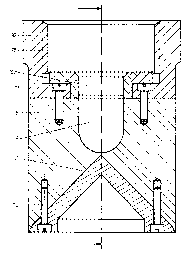
Fig. 1 schematically shows that a conical jacket 2 having
a plane conical surface is arranged in the flue gas duct l,
said conical jacket being disposed in the center relative to
the direction of flow 3 of the lime milk suspension. The
feed tube for the lime milk suspension is denoted by 4, such
tube being connected with a manifold 5 arranged crosswise
relative to the feed tube. The mounting device for the conical
jacket 2 is schematically shown denoted by 6.
It is obvious that when the lime milk suspension is
admitted via the tube 4, it impacts the conical jacket 2 and
uniformly distributes itself across the surface of the plane
conical jacket, so that a liquid jacket 7 is formed, which
covers the cross sectional area through which the flue gases
pass. The flue gases flowing in the flue gas duct 1 are
almost completely acted upon by said liquid jacket and thus
brought into contact with the lime milk suspension, whereby
_7_
WO 94/15700 PCT/DE93/00914
the known chemical reaction occurs there (formation of gypsum .
Fig. 2 shows the mounting for the conical jacket 2 in
detail; it can be seen that the conical jacket is supported
with the help of a bridge plate 8, which is arranged in
the center relative to the outlet opening l0a of the
feed tube 10 and has a recess 9 in the center.
The bridge plate 8 is fastened on the feed tube 10
with the help of the screws 11. The bridge plate 8 is fastened
on the conical jacket with the hrlp of the screws 12. The
thread fastening of the feed tube 10 is denoted by 13.
From this follows that the flowing liquid flows within the
walls of the thread fastening 13 to the conical jacket 2,
and that the conical surface of the conical jacket 2 has
a certain spacing from the outlet opening 10a of the feed
tube 10. If the diameter of the outlet opening l0a is
smaller, the spacing of the conical tip from the outlet
opening is smaller as well, and vice-versa. For changing
the diameter of the outlet opening 10a, an exchangeable
nozzle can be fitted with said outlet opening and the
corresponding tearing edge (cf Fig. 4).
Fig. 4 shows a different support for the conical
jacket 2. Said support is arranged eccentrically relative to
_g_
2153773
WO 94/15700 PCT/DE93/00914
the outlet opening l0a and consists of the bridges 14, which
are mounted on the feed tube 10 distributed across the
circumference. The conical jacket is fastened on the bottom
end of the bridge with the help of a streamlined, saddle-like
sword 17. A fastening screw 20 projects into the bridge, by
which the conical jacket is held on the feed tube.
The streamlined, saddle-like sword 17 is particularly
illustrated in Fig. 5, which shows that the sword is designed
blade-like (at 17a) on the side facing the flow. The
attachment point 17b of the blade 17a of the sword 17 on the
conical jacket 2 is selected in such a way that the
attachment point 17b is disposed approximately aligned
beneath the inner wall lOb of the feed tube l0a (Fig. 4).
In this connection, following the streamlined mounting of
the cone in the off-flow direction, sufficient conical surface
is still available (at 2b) in order to assure the formation
of the gutter-free liquid jacket.
This embodiment, too, assures that the liquid impacting
the conical jacket distributes itself on the latter, and that
thus a liquid jacket is created with as little formation of
gutters as possible, covering the entire cross sectional area
of the flue gas duct.
_g-
~1_~3'l?3
WO 94/15700 PCT/DE93/00914
Fig. 6 shows yet another embodiment, in which the
conical jacket 2 is supported with the help of one
single bridge 14a arranged eccentrically relative to the
center line of the outlet opening of the feed tube 10.
The special feature here is that the conical tip 2a of the
cone is disposed laterally displaced against the center
line 21 of the outlet opening l0a of the feed tube 10.
It is possible in this way to discharge the solids
contained in the lime milk suspension unilaterally. With
a suitable arrangement of such an embodiment in the flue
gas duct, it is possible to accomplish that the inside
coating of the flue gas duct is subjected to less wear
because only a minor portion of the solid particles will
then come into contact with the wall.
With such an embodiment too, the conical jacket is
mounted with the help of a streamlined, saddle-like sword 17,
which has a blade 17a on the side facing the flow. The
bridge 14 is held by the screws 15.
The representation also shows that with all embodiments
of the same type, sufficient conical surface is available
(at 2b) following the streamlined mounting of the cone in
the direction of off-flow in order to assure the formation
-10-
2~t.~3~'~~
w0 94/15700 PCT/DE93/00914
of the gutter-free liquid jacket. So that the smoothest
possible flow is obtained when the liquid flows off the
conical jacket, provision can be made in all embodiments
within the edge zone 2a of the conical jacket for a
liquid tear-off edge in the form of an angle 18, which
is denoted by 19.
Fig. 7 shows a top view of the object according to
Fig. 6 within the zone of section VII-VII, which illustrates
that the by far largest area of the conical jacket is a
free surface.
-11-