Note: Descriptions are shown in the official language in which they were submitted.
CA 02153958 2005-09-08
FIELD OF THE INVENTION
The invention comprises a pipe coupling.
BACKGROUND
Various forms of couplings for piping formed of plastics materials are known.
The
present invention provides an improved or at least alternative form of pipe
coupling.
SUMMARY OF THE INVENTION
In broad terms the invention comprises a a pipe coupling comprising: a body
part
including a hollow interior for fluid flow through the coupling, a rotatable
sleeve
captively mounted to the body part in a longitudinally fixed position on the
body part of
the coupling such that an end of a length of pipe connected to the hollow
interior of the
body part of the coupling enters the coupling at a pipe entry end of the
rotatable sleeve
and passes through the rotatable sleeve to the hollow interior of the
coupling, the
rotatable sleeve having a tapered interior of narrowing diameter towards the
pipe entry
end of the rotatable sleeve, a circular band coaxially positioned inside the
rotatable
sleeve, through the interior of which circular band a pipe end passes and is
engaged by
being pushed into the rotatable sleeve to connect to the hollow interior of
the body part
of the coupling, and which circular band is forced to further close about the
pipe end by
the co-action of said tapered interior of the rotatable sleeve and pulling the
pipe end
longitudinally away from the coupling, and coupling means to couple the
circular band
-1-
CA 02153958 2005-09-08
1
to the interior of the rotatable sleeve, whereby rotation of the sleeve
further secures the
circular band to the pipe.
Preferably, the circular band has a threaded interior such that rotation of
the sleeve will
thread the band around the exterior of the pipe end. The rotatable sleeve may
be given a
few turns to rotate the threaded circular band around the exterior of a pipe
end pushed
into the coupling to thread the threaded band onto the exterior of the pipe
end to further
link the pipe to the coupling. In preferred forms of the pipe coupling the
rotatable sleeve
may be rotated in the opposite direction to allow the pipe to be released or
removed from
the coupling.
Pipe couplings of the invention may be formed as "straight" couplings which
are used to
couple two pipe ends together in line. Alternatively pipe couplings of the
invention may
be formed as "elbows" i.e. right angles or similar, T's i.e. a coupling for
connecting three
pipe ends together, or as a coupling to connect a pipe end to a piece of
equipment such as
a pump or similar.
DESCRIPTION OF DRAWINGS
The invention will be further described with reference to the accompanying
drawings
which show a preferred form coupling of the invention intended for coupling a
pipe end
to a piece of equipment, by way of example. In the drawings:
-2-
Figure 1 shows the preferred form coupling with a length of pipe connected to
the coupling,
Figure 2 shows the coupling in cross-section, showing the end of a lez~th of
pipe pushed into
the coupling but before rotation of the rotatable sleeve to screw the circular
band onto the
pipe end,
Figure 3 shows the coupling i~a cross-section similar to Figure 2 but after
rotation of the
rotaxable sleeve,
Figures 4 and 5 show the body part and circular band of the coupling with the
rotatable sleeve
removed,
Figure 6 shows a "straight" coupling of the invention for coupling two pipe
ends togethier in
line, and
Figurc 7 shows a circlip which holds the rotatable sleeve to the body part of
the coupling as
will be described
DESCRIPTION OF PREFERRED FORM
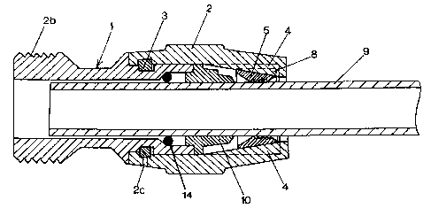
The coupling comprises a body part generally indicated at 1 to which is
mounted a rotatable
collar or sleeve 2. The sleeve 2 may have a knurled exterior for hand gripping
or a hexagonal
exterior as indicated at 2a so that in use it can be turned with a spanner if
necessary.
-3-
2.~~~9~8
The sleeve 2 can be rotatod relative to the body part 1 of the coupling as
indicated by arrow
A in Figure 1, and the sleeve 2 is eaptivcly mounted on the body part 1 of the
coupling, in
the preferred form shown by a circlip 3 mounted in as annular recess about the
body part of
the coupling engaging into a corresponding annular recess in the internal wall
of the coupling
nut (see Figures 2 and 3). The circlip 3 is shown separately in Figure 7.
The rotatable sleeve 2 has a tapered interior which narrows towards the pipe
entry end of the
rotatable sleeve as shown in Figures 2 and 3. In the preferred form coupling
shown in the
drawings the rotatable sleeve 2 also has a number of longitudinal slots or
grooves 4 about its
tapered interior, running parallel with the longitudinal axis of the coupling.
These slots or
gmoves 4 can be seen from the exterior of the end of the rotatable sleeve in
Figure 1, and are
indicated in broken lines in Figtues 2 and 3.
A circular band 5 is positioned inside the rotatable sleeve 2 - see Figures 2
and 3. The band
can also be seen in Figures 4 and 5 which show the coupling with the ratatable
sleeve 2
removed. The band 5 is split at a point b somewhat like a circlip. The
exterior of the band
S engages the tapered interior of the rotatable sleeve 2, such that as the
circular band 5 is
moved towards the pipe entry end of the rotatable sleeve 2 where the internal
diameter of the
rotatable sleeve 2 is smallest, the band 5 will be forced to close further.
Preferably the
exterior of the circular band 5 is also tapered with a reducing diameter
towards the pipe entry
end of the coupli~og so that it will better covet with the tapered interior of
the rotatable sleeve
2.
-4-
2.~~39~8
The body of the coupling shown in the drawings has a threaded end 2b for
screwing into the
inlet or outlet fitting of s pump yr other piece of equipment.
In use of the coupling, when a pipe end 9 is pushed into the interior of the
rotatable sleeve
2 it will also pass through the interior of the circular band 5. As the pipe
end onters the
coupling and passes through the circular band 5 it will tend to push the
circular band back
slightly so that the pipe can easily pass through the circular band and fully
into the coupling
and through an O-ring 14 which is preferably included to provide a fluid tight
seal between
the coupling and the pipo. When the pipe is subsequently pulled back away from
the
coupling, it will pull the circular band back towards the pipe entry end of
the rotatable sleeve
2 where the internal diameter of the rotatable sleeve 2 is smallest, in so
doing forcing the
band to close or clamp more tishtly about the pipe to grip the pipe end and
link the pipe to
the coupling. The interior of the circular band 5 may be threaded as will be
further described,
or alternatively tray be simply provided with barbs which will bite into the
exterior of the
pipe as the circular band is forced to clamp more tightly about the pipe by
the tapered interior
of the rotatable sleeve 2, or other roughened grippung surface to the internal
band.
In the preferred form coupling the circular band 5 has a raised tab 8 - see
Figures 4 and 5.
This tab 8 engages into any of the slots 4 in the interior of the rotatable
sleeve 2 {see Figures
2 and 3 where the tab is shown in dotted lines), so that the circular band 5
is effectively
coupled to the rotatable sleeve and will rotate with the rotatable sleeve 2.
In the preferred
form coupling shown in the drawings the circular band 5 also has a threaded
interior as
shown. The arrangement is such that if the sleeve 2 is turned, the band 5 will
also be rotated
_ 5 ..
2~~3~958
around the pipe 9, because of the tab 8 engaging into a slot 4 of the rotating
sleeve 2, and the
threads of the band 5 will thread onto the pipe end. The hand of the threads
on the interior
of the band 5 is such that as the band 5 is turned about the pipe end in one
direction it will
move on the pipe towards the pipe entry end of the coupling. As it so threads
onto the
exterior of the pipe, because of the tapered interior of the rotatable sleeve
2 as described, the
circular band S will at the same time be forced to close more as it moves, so
gripping or
clamping the pipe end. The sleeve 2 may be rotated, typically by hand and
finally by a
spanater.
In the preferred form coupling shown in the drawings the circular band 5 is
split at 6 as
described previously, and in addition it is wider on one side of the split 6
than on the other
to give the circular band a protruding nose 12 as shown in Figures 4 and 5.
'T"he body part
of the coupling has a shaped complementary part 13 as shown and the
arrangement is such
that to release the pipe end from the coupling, the rotatablc sleeve 2 may be
rotated in the
opposite direction to move the threaded band 5 back away from the pipe entry
end of the
coupling until the nose 12 of the band 5 catches the shaped part 13 of the
body of the
coupling. This will then cause the threaded band 5 to be opened slightly as
shown in Figure
5, so that the pipe end can be withdrawn back off the coupling, Also, the
entrance to the
interior of the circular band is tapered towards the threaded interior of the
circular band 5.
This further assists in opening the circular band when the nose 12 of the band
5 catches the
shaped part 13 of the body of the coupling, as at the same time the annular
portion of the
body of the coupling surrounding the aperture into the body of the coupling
through which
the pipe end passes engages the tapered entry to the band S to fiu~ther open
the band S. Less
-6-
~'I ~~9 ~8
preferred forms of the coupling may not include such a release system as
described above but
the release system shown in the drawings is proferred.
The preferred form coupling has a number of grooves 4 through the interior of
the sleeve 2
as described, but in fact only one groove 4 or equivalent to engage the tab 8
or similar is
essential. Alternatively, the band 5 may have a number of tabs 8 or similar
spaced about its
circumference, which are engaged by a number of groovos along the interior of
the rotatable
sleeve 2.
Referring again to the circlip 3, should it be desirable or xaecessary to
remove the rotatable
sleeve 2 from the body part 1 of the coupling, a small pin such as a small
nail is inxrtcd
through a small hole 2c through the inner end of the coupling nut adjacent the
circlip, as
shown in Figures 2 and 3. The circlip has one end formed into a tab 3a which
engages into
a corresponding hole in the bottom of the annular recess about the body part
of the coupling
in which the circlip is housed. With the pin inserted through the hole 2e, the
sleeve 2 is
rotated until the end of the pin drops into the groove 3b across the other end
of the circlip.
The sleeve 2 is then rotated a little more to close the circlip, the other end
3a of the circlip
being caught as described, which then enables the rotatable sleeve 2 to be
withdrawn back off
the body 1 of tire coupling.
The O-ring 14 can preferably mov a in a shaped recess behind the body part 10
and the main
body 1. The O-ring provides a positive seal for both negative and positive
pressures. For a
negative pressure the O-ring 14 is drawn back into the position shown in Figs
2 and 3, wlxere
2.~~~5
the O-ring is forced up a taper to give a positive seal between the pipe end 9
acrd the main
body 1. For pasitive pressures the O-ring 14 is forcod away from the pipe end
and forras a
aeal between the pipe, the main body 1 and the body part 10.
As stated the preferred form coupling shown in Figures 1 to 5 is intended to
couple a pipe
end to a piece of equipment such as a pipe. Figure 6 shows a "straight
coupling" for coupling
two pipc cads together in line. The design of the coupling on each side is the
same as shown
in Figures 1 to 5. The coupling may also be formed in other configurations
such as an
"elbow" coupling similar to tho straight coupling of Figure 6 but with a bend
of any desired
angle or as a T coupling for coupling three pipe ends together.
The forgoing describes the invention including a preferred form thereof.
Alterations and
modifications as will be obvious to those skilled in the art are intended to
be incorporated
within the scope hereof as defined in the fvliowing claims.
_g_