Language selection

Search

Patent 2154088 Summary

Third-party information liability

Some of the information on this Web page has been provided by external sources. The Government of Canada is not responsible for the accuracy, reliability or currency of the information supplied by external sources. Users wishing to rely upon this information should consult directly with the source of the information. Content provided by external sources is not subject to official languages, privacy and accessibility requirements.

Claims and Abstract availability

Any discrepancies in the text and image of the Claims and Abstract are due to differing posting times. Text of the Claims and Abstract are posted:

  • At the time the application is open to public inspection;
  • At the time of issue of the patent (grant).
(12) Patent: (11) CA 2154088
(54) English Title: COIN ESCALATOR FOR GAMING DEVICES
(54) French Title: DISPOSITIF DE TRANSPORT DE PIECES DE MONNAIE POUR MACHINES DE JEU
Status: Expired and beyond the Period of Reversal
Bibliographic Data
(51) International Patent Classification (IPC):
  • G07D 01/00 (2006.01)
  • A63F 03/00 (2006.01)
  • G07D 09/00 (2006.01)
(72) Inventors :
  • ROTHSCHILD, WAYNE H. (United States of America)
  • SOYKA, EDWARD J. (United States of America)
  • HAUSMAN, HERBERT H. (United States of America)
  • PIRZADEH, JOE (United States of America)
(73) Owners :
  • WMS GAMING INC.
(71) Applicants :
  • WMS GAMING INC. (United States of America)
(74) Agent: MARKS & CLERK
(74) Associate agent:
(45) Issued: 2000-05-09
(22) Filed Date: 1995-07-18
(41) Open to Public Inspection: 1996-01-30
Examination requested: 1997-06-24
Availability of licence: N/A
Dedicated to the Public: N/A
(25) Language of filing: English

Patent Cooperation Treaty (PCT): No

(30) Application Priority Data:
Application No. Country/Territory Date
283,384 (United States of America) 1994-07-29

Abstracts

English Abstract


The improved coin escalator of the invention includes a
smoothly curved coin transport channel positioned on the outside
circumference of an arcuate back plate. The channel is defined
by spacer plates which are attached to the outer curved surface
of the back plate and edge plates integral with the spacer
plates. Downtime of the gaming device is minimized because the
smoothly curved shape of the transport channel prevents coins
from becoming jammed therein.


Claims

Note: Claims are shown in the official language in which they were submitted.

What is Claimed is:
1. A coin escalator for use in a gaming device for conveying coins from a coin
hopper
to a discharge point above the hopper comprising:
a) an elongated, arcuate back plate having a smoothly curved outside surface
without abrupt transitions, having a width at least equal to the diameter of
the coins; and
b) means defining a coin transport channel on the outside surface of said
plate,
said coin transport channel defining means being spaced from the outside
surface of the back plate
by a distance at least equal to the thickness of the coins, the back plate
extending continuously across
the width of the coin transport channel.
2. The improved escalator of claim 1 wherein said means defining a coin
channel includes
a pair of spacer plates attached to the outside surface of said back plate and
an edge plate integral
with each spacer plate.
3. In combination, a gaming device and an improved coin escalator for use in
the gaming
device, the combination comprising:
a) a payoff hopper for storing coins in the gaming device;
b) a payout trough disposed at a position above said coin hopper on the gaming
device; and
7

c) a coin escalator for conveying coins from said coin hopper to said payout
trough, the escalator including:
i) an elongated, arcuate back plate having a smoothly curved surface
without abrupt transitions, and having a width at least equal to the diameter
of the coins; and
ii) means defining a coin transport channel on the outside surface of said
back plate, said coin transport channel defining means being spaced from the
outside surface of the back plate by a distance at least equal to the
thickness
of the coins, the back plate extending continuously between the coin transport
channel defining means.
4. The combination of claim 3 wherein said means defining a coin transport
channel
includes a pair of spacer plates attached to the outside surface of said back
plate and an edge plate
integral with each spacer plate.
8

Description

Note: Descriptions are shown in the official language in which they were submitted.


CA 02154088 1999-06-04
COIN ESCALATOR FOR GAMING DEVICES
BACKGROUND AND SUMMARY OF THE INVENTION
The present invention generally relates to the handling of coins
in gaming devices and, more particularly, to an improved coin escalator
for transporting coins from a payout hopper in a gaming device to a
payout trough positioned above the hopper on the device. Gaming devices
typically consist of a cabinet supporting a video screen which displays
a game as directed by the game program associated with a computer
control system. Alternatively, the cabinet could support a plurality of
reels, such as those commonly found on slot machines. The player
manipulates buttons provided on the cabinet to play the game in an
attempt to win a payout.
Gaming devices typically are provided with a coin hopper which is
capable of storing coins deposited by game players and driving stored
coins into a coin escalator. The escalator transports coins which are
driven into it to a payout trough which normally is disposed at a point
above the coin hopper. A coin counter, associated with the escalator,
signals the computer control system the amount of coins that have been
dispensed to the player.
Typically, the coins travel on the curved inner surface a back
plate of the escalator past a transition point of unequal radius. On

CA 02154088 1999-06-04
existing escalators, the coins often "shingle," that is the edges of
adjacent coins become overlapped thereby jamming the device.
Referring to Figure 2, a prior art coin escalator and hopper
combination is illustrated. Coin hopper 24 is open at its top 30 to
receive coins deposited into coin slots 20 and is removably secured to
escalator 26 by bracket 32. Hopper 24 and escalator 26 are supported on
mounting sled 36. Sled 36 includes a frame 38 supported on a plurality
of rollers 40 and 42 which engage with a suitable mounting structure on
the bottom of cabinet 12 to correctly orient the hopper 24 therein.
Alternatively, the hopper 24 and escalator 26 could be attached to a
mounting plate in the bottom of cabinet 12.
A coin transport path is defined along the inside arc of the back
plate 52 of 26. Escalator 26 is connected to the payout trough 22 via
delivering arm 28 to convey coins from hopper 24 to the payout trough.
Due to the abrupt change of direction at the junction 48 of the lower
escalator portion 44 and upperportion 46, coins tend to jam or become
shingled.
Figure 2A is an enlargement of the junction 48 in escalator 26
where coins frequently become jammed. For example, coins 57 and 59 are
shingled and block the transport path in escalator 26 because their
edges are overlapped. Down time of the gaming machine is increased
because a coin jam has to be manually released. A typical solution to
this problem, although not foolproof, is to provide a plurality of
2

CA 02154088 1999-06-04
spring loaded bearings at juncture 48 to reduce the shingling effect by
guiding the
coins past the transition.
One solution to this problem is to provide a plurality of spring loaded
bearings
or other means at the abrupt transition to prevent or reduce shingling. These
solutions
unnecessarily increase the costs of manufacturing coin escalators and are not
a
foolproof solution. Thus, an improved coin escalator is desired in which the
risk of
coin "shingling" is minimized.
Coin shingling is minimized in the present invention by the use of a smoothly
curved coin transport channel positioned on the outer surface of the
escalator.
Because there are no abrupt transitions, the likelihood of coins jamming in
the
escalator during transport is minimized.
Accordingly, in one aspect of the present invention there is provided a coin
escalator for use in a gaming device for conveying coins from a coin hopper to
a
discharge point above the hopper comprising:
a) an elongated, arcuate back plate having a smoothly curved outside
surface without abrupt transitions, having a width at least equal to the
diameter of the
coins; and
b) means defining a coin transport channel on the outside surface of said
plate, said coin transport channel defining means being spaced from the
outside
surface of the back plate by a distance at least equal to the thickness of the
coins, the
back plate extending continuously across the width of the coin transport
channel.
According another aspect of the present invention there is provided in
combination, a gaming device and an improved coin escalator for use in the
gaming
device, the combination comprising:
a) a payoff hopper for storing coins in the gaming device;
b) a payout trough disposed at a position above said coin hopper on the
gaming device; and
-3-

CA 02154088 1999-06-04
c) a coin escalator for conveying coins from said coin hopper to said
payout trough, the escalator including:
i) an elongated, arcuate back plate having a smoothly curved
surface without abrupt transitions, and having a width at least equal to the
diameter of
the coins; and
ii) means defining a coin transport channel on the outside surface
of said back plate, said coin transport channel defining means being spaced
from the
outside surface of the back plate by a distance at least equal to the
thickness of the
coins, the back plate extending continuously between the coin transport
channel
defining means.
BRIEF DESCRIPTION OF THE DRAWINGS
An embodiment of the present invention will now be described more fully
with reference to the accompanying drawings in which:
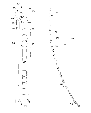
Figure 1 shows a perspective view of a gaming device suitable for use with the
present invention.
Figure 2 illustrates a prior art coin hopper and escalator assembly.
Figure 2A is an enlargement of a portion of the coin escalator of Figure 2.
-3a-

CA 02154088 1999-06-04
Figure 3 is a rear view of the improved coin escalator of the
invention.
Figure 4 is a side view of the improved coin escalator of the
invention.
DETAILED DESCRIPTION OF A PREFERRED EI~ODIMENT
Referring to Figure 1, a perspective view of a gaming device 10
which incorporates the present invention is illustrated. Gaming device
includes a cabinet 12 which supports a video screen 14 and a
plurality of switch or touch screen control buttons 16 that are
manipulated by the player to control play of the game. Alternatively,
video screen 14 could be replaced by a plurality of mechanical reels or
the like for use as a slot machine.
Gaming machine 10 includes a bill entry 18 and coin slots 20. Coin
slots 20 serve to deliver the inserted coins into a hopper 24 (Figure
2) and bill entry 18 delivers the inserted bills into a bill validator
and stacker (not shown). If a player wins and wishes to cash out, then
the payoff is deposited into payout trough 22 as discussed hereafter.
Typically, a coin escalator 26 is used to transport coins from hopper
24 to payout trough 22 via delivering arm 28 (Figure 2).
4

CA 02154088 1999-06-04
Referring to Figures 3 and 4, the improved coin escalator 50 of the
invention is illustrated. A smoothly curved coin transport channel 66,
without any abrupt transitions, is positioned on the outside surface of
arcuate back plate 52. Channel 66 is defined by arcuate back plate 52,
spacer plate 54 and edge plate 62, and spacer plate 56 and edge plate
64. Spacer plate and edge plate pairs 54 and 62 and 56 and 64 preferably
are a single element, although separate spacer and edge plates could
utilized. Channel 66 has a width which is slightly greater than the
diameter of the coins for which it is designed and has a depth which is
slightly larger than the thickness of such coins.
First and second upper guides 58 and 60 are attached at the top of
back plate 52 to direct coins, such as coin 68, into the payout trough
22 via conventional means such as the counter arm 28 of Figure 2. In
operation, coins are received from hopper 24 at end 72 via a
conventional coin mechanism, travel up coin channel 66 on the outside
of back plate 52 and are discharged into coin trough 22 at end 74. A
conventional switch means (not shown), such as an optical switch, is
provided at notch 70 (Figure 3) to count the number of coins dispensed
into trough 22.

2154088
As seen in Figure 4, escalator 50 is arcuate in shape
such that coin transport channel 66 contains no abrupt
transitions where coins could jam or become shingled. The coin
path 66 may be shaped as illustrated because coins travel up
escalator 50 on the outside circumference of back plate 52.
Thus, there is no need to include spring loaded bearings or other
anti-jam arrangements to facilitate coin travel.
While the invention has been illustrated and described
in detail in the drawings and foregoing description, the same is
to be considered as illustrative and not restrictive in
character, it being understood that only the preferred embodiment
has been shown and described and that all changes and
modifications that come within the spirit of the invention are
desired to be protected.
- 6 -

Representative Drawing
A single figure which represents the drawing illustrating the invention.
Administrative Status

2024-08-01:As part of the Next Generation Patents (NGP) transition, the Canadian Patents Database (CPD) now contains a more detailed Event History, which replicates the Event Log of our new back-office solution.

Please note that "Inactive:" events refers to events no longer in use in our new back-office solution.

For a clearer understanding of the status of the application/patent presented on this page, the site Disclaimer , as well as the definitions for Patent , Event History , Maintenance Fee  and Payment History  should be consulted.

Event History

Description Date
Time Limit for Reversal Expired 2006-07-18
Inactive: IPC from MCD 2006-03-11
Letter Sent 2005-07-18
Inactive: Late MF processed 2004-07-26
Letter Sent 2004-07-19
Grant by Issuance 2000-05-09
Inactive: Cover page published 2000-05-08
Pre-grant 2000-02-09
Inactive: Final fee received 2000-02-09
Notice of Allowance is Issued 1999-10-08
Letter Sent 1999-10-08
Inactive: Approved for allowance (AFA) 1999-09-20
Amendment Received - Voluntary Amendment 1999-06-04
Inactive: S.30(2) Rules - Examiner requisition 1999-03-24
Amendment Received - Voluntary Amendment 1997-08-29
Letter Sent 1997-08-04
Inactive: Application prosecuted on TS as of Log entry date 1997-07-30
Inactive: Status info is complete as of Log entry date 1997-07-30
All Requirements for Examination Determined Compliant 1997-06-24
Request for Examination Requirements Determined Compliant 1997-06-24
Application Published (Open to Public Inspection) 1996-01-30

Abandonment History

There is no abandonment history.

Maintenance Fee

The last payment was received on 1999-07-14

Note : If the full payment has not been received on or before the date indicated, a further fee may be required which may be one of the following

  • the reinstatement fee;
  • the late payment fee; or
  • additional fee to reverse deemed expiry.

Patent fees are adjusted on the 1st of January every year. The amounts above are the current amounts if received by December 31 of the current year.
Please refer to the CIPO Patent Fees web page to see all current fee amounts.

Fee History

Fee Type Anniversary Year Due Date Paid Date
Request for examination - standard 1997-06-24
MF (application, 3rd anniv.) - standard 03 1998-07-20 1998-06-25
MF (application, 4th anniv.) - standard 04 1999-07-19 1999-07-14
Final fee - standard 2000-02-09
MF (patent, 5th anniv.) - standard 2000-07-18 2000-07-14
MF (patent, 6th anniv.) - standard 2001-07-18 2001-07-04
MF (patent, 7th anniv.) - standard 2002-07-18 2002-06-17
MF (patent, 8th anniv.) - standard 2003-07-18 2003-06-25
Reversal of deemed expiry 2004-07-19 2004-07-26
MF (patent, 9th anniv.) - standard 2004-07-19 2004-07-26
Owners on Record

Note: Records showing the ownership history in alphabetical order.

Current Owners on Record
WMS GAMING INC.
Past Owners on Record
EDWARD J. SOYKA
HERBERT H. HAUSMAN
JOE PIRZADEH
WAYNE H. ROTHSCHILD
Past Owners that do not appear in the "Owners on Record" listing will appear in other documentation within the application.
Documents

To view selected files, please enter reCAPTCHA code :


To view images, click a link in the Document Description column. To download the documents, select one or more checkboxes in the first column and then click the "Download Selected in PDF format (Zip Archive)" or the "Download Selected as Single PDF" button.

List of published and non-published patent-specific documents on the CPD .

If you have any difficulty accessing content, you can call the Client Service Centre at 1-866-997-1936 or send them an e-mail at CIPO Client Service Centre.


Document
Description 
Date
(yyyy-mm-dd) 
Number of pages   Size of Image (KB) 
Claims 1999-06-03 2 47
Description 1999-06-03 7 215
Drawings 1999-06-03 3 55
Description 1996-01-29 6 175
Drawings 1996-01-29 3 56
Abstract 1996-01-29 1 14
Claims 1996-01-29 2 42
Representative drawing 1998-01-27 1 16
Representative drawing 2000-04-09 1 8
Acknowledgement of Request for Examination 1997-08-03 1 178
Commissioner's Notice - Application Found Allowable 1999-10-07 1 164
Maintenance Fee Notice 2004-08-18 1 172
Late Payment Acknowledgement 2004-08-18 1 165
Maintenance Fee Notice 2005-09-11 1 172
Correspondence 1995-09-14 18 485
Correspondence 2000-02-08 1 50
Fees 1998-06-24 1 55
Fees 1999-07-13 1 50
Fees 1997-01-16 1 59
Courtesy - Office Letter 1995-09-10 2 81