Note: Descriptions are shown in the official language in which they were submitted.
WO g4/17311 ~i 2 1 5 ~ 1 7 7 PCr/SE94/00041
A DRIVING DEVICE
Field of the invention and prior art
This invention is related to a driving device according to the
precharacterizing parts of the appending patent claims 1 and 7.
15 The driving device according to the invention may be used in
any conceivable connections where it is desired to put a
working member in motion. Although it can be mentioned as an
example that the working arrangement could form a part of
machines for splitting wood pieces, more specifically so called
20 fire wood cleaving machines, it can be mentioned as other
examples on applications general use as jacks, presses,
bending apparatus etc, the working member of course being
provided with an arbitrary tool for carrying out the function
aimed at.
Fire wood cleaving machines of the kind mentioned in the
introduction are known per se. By way of example, reference
can be made to WO 92/11 980 (PCT/SE 91/00914), the Euro-
pean patent publication No. 0 051 853, the Swedish publication
30 for inspection No. 7904914-4 (416 903) and the Swedish
publication for inspection No. 8304029-5 (453 898).
The two first mentioned publications are particularly interesting
in the present connection. The devices more closely described
35 therein suffer from several important disadvantages. One of
WO 94/17311 PCT/SE94/00041
2~s4~7~ 2
these disadvantages resides in the need for springs for return-
ing the working member to a starting position, these springs
having to be tensioned during the working stroke. Such springs
tend to become fatigued with time, which requires exchange of
5 springs. Furthermore, power for tensionin.g. the springs is
required during the working stroke, which`increases the total
power requirement of the working arrangement. Besides it
should be pointed out that the need for`such springs makes the
embodiment complicated and necessitates also as a rule, at
10 least in more simple embodiments, need for an increased
length of the working arrangement. Finally, the work in connec-
tion with mounting and replacement of such springs is risky
since the springs must be applied with some pretensioning.
15 Another disadvantage with the prior art is that the costs for the
driving devices tend to be relatively high. In WO 92t11980 it is
intended to use an internal combustion engine combined with a
hydraulic pump of the kind normally appearing in hydraulic drive
applications. In the European patent publication 0 051 853 it is
20 suggested to use a part of a portable power saw and to com-
bine this power saw part with a hydraulic pump. Such power
saws are normally rather costly and will in this intended
application require a specially manufactured hydraulic pump or
at least a specially manufactured coupling part. Usage of the
25 power saw part for its regular purpose requires dismounting of
the hydraulic pump and application of power saw sword, chain
etc.
SUMMARY OF THE INVENTION
The present invention aims at reducing the disadvantages
discussed hereinabove.
According to a first aspect of the concept of the invention it is
35 intended to provide ways to design the means for returning the
WO 94/17311 215 41~ ~ PCTISE94/00041
working chamber to a starting position without one having to
rely on springs or similar elements based upon power accumu-
lation. This aspect of the invention is fulfilled by that primarily
defined in claim 1, namely an ejector arrangement adapted to
5 achieve evacuation of the working chamber and thereby return-
ing of the working member by creating a negative pressure in
the working chamber.
According to a second aspect of the invention it is aimed at
10 providing ways to reduce, to a minimum, the cost of the hydrau-
lic fluid source, the latter at the same time being adapted to
easily be used for alternative purposes without requiring
substantial dismounting or mounting work. Essential in this con-
nection is, furthermore, that the hydraulic fluid source aimed at
15 should be relatively widely spread and be possible to purchase
at a reasonable price.
This second aspect of the invention is fulfilled by the hydraulic
fluid source being constituted by a high pressure washing unit
20 known per se or of an arbitrary nature. In that way a relatively
non expensive unit is used as the hydraulic fluid source, said
unit having a valuable alternative use after an easily executable
decoupling of conduits by means of suitable quick couplings.
Essential for this aspect of the invention is, as is defined in
25 claim 7, that a fluid circulation is formed so that the fluid used,
normally water, always circulates in the circulation when the
working member is passive. When the working member is to be
activated, the valve will, as a consequence of that defined in
claim 9, divert the entire or a part of the flow of the circulation
30 towards the working chamber. In order to avoid detrimental
overpressure conditions it is suitable to provide, as defined in
claim 12, a pressure restriction valve.
WO 94/17311 PCTISE94/00041
2154i77 4
Other advantages and features of the construction according to
the invention appear more closely by the following description
and the rest of the claims.
5 SHORT DESCRIPTION OF THE DR~WINGS .
With reference to the enclosed drawings a more specific
description of an embodiment example of the invention is
presented hereunder.
In the drawings
Fig. 1 is a diagrammatical side view of the driving device
according to the invention applied on a fire wood cleaving
1 5 machine;
Fig. 2 is a view similar to Fig. 1 but illustrating a state of
operation; and
20 Fig. 3 is a partly cut and enlarged view illustrating parts of the
fire wood cleaving machine and the driving device according to
the invention.
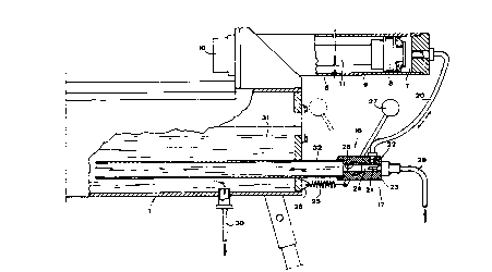
DETAILED DESCRIPTION OF A PREFERRED EMBODIMENT
The fire wood cleaving machine illustrated in the drawings
comprises a base generally denoted 1 and being adapted to be
supported relative to the underlayer by means of suitable
supports or legs 2.
The base 1 comprises at its upper part a support surface 3 for
receiving wood pieces. This surface may for instance be cross
sectionally V- or U-shaped in order to form a seat for the wood
pieces. At one end of the support surface there is arranged on
35 the base 1 at least one edge member 4. This edge member 4
WO 94/17311 2 1 5 ~ 1 7 7 ~1SE9410~l
protrudes upwardly above the support surface 3 and may be ar-
ranged on a bracket like holder 5. At the other end of the
support surface 3 a working arrangement 6 is provided. This
has (see Fig. 3) a working chamber 7 intended for receiving hy-
5 draulic fluid and a working member 8 adapted to be put inmotion on respective fluid supply to and fluid evacuation from
the working chamber 7. A basic part 9 of the working arrange-
ment 6 is rigidly connected to the base 1. The working member
8 is adapted to move relative to this basic part 9. The working
10 member 8 comprises, preferably, a particular contact member
10 adapted to contact the wood piece.
In the example the working arrangement has the character of a
hydraulic cylinder, the cylinder being formed by the basic part 9
15 and the piston of the working member 8. The contact member
10 is arranged at the extreme end of the piston rod 11 of the
piston 8.
When the piston 8 is caused to move relative to the cylinder 9,
20 the contact member 10 will hit a wood piece denoted 12 in Fig.
2 and force the same to move relative to the fixed edge member
4 so that a cleavage function occurs.
In case it would be desired to be able to use the device de-
25 scribed for other pressing or power application purposes thanfire wood cleaving per se, there may be on the base 1 fixing
means 13, e.g. fixing holes, for securing particular dollies or
other auxiliary equipment intended for specific work purposes,
said equipment being intended to function in co-operation with
30 the power generating working arrangement 6.
The driving device according to the invention comprises a
source 14 of hydraulic fluid under pressure. Conduits collec-
tively designated 15 are provided for respective supply to and
35 evacuation from the working chamber 7 of hydraulic fluid. A
WO 94/17311 PCT/SE94/00041
,2~.s ~ 6
valve 16 is adapted to, in a first state (Fig. 2), direct fluid to the
working chamber 7 and, in a second state (Figs. 1 and 3), allow
evacuation of fluid from the working~chamber. Means 17 are
provided for returning the working ` niember 8 to a starting
5 position (Figs. 1 and 3).
.
The returning means 17 comprises an ejector arrangement
adapted to generate a negative pressure in the working cham-
ber 7 for evacuating the same as a consequence of flow of fluid
10 through the ejector arrangement.
The hydraulic fluid source 14 comprises a pump 18 and a motor
19 driving the same, suitably an electric motor even if also
other types of motors, e.g. internal combustion engines, may be
15 in question.
The pump 18 of the hydraulic fluid source 14, the conduits 15,
more specifically parts of these conduits, and the valve 16,
when it is in its second state (Figs. 1 and 3), define a fluid
20 circulation, in which the ejector arrangement 17 is provided,
there being a connection 20 between the ejector arrangement
17 and the working chamber 7. In the example this connection
20 has the character of a conduit of a certain length but it
should be noted that the connection 20 i practice could be
25 extremely short, namely in case the ejector arrangement 17
would be provided close to or integrated with the working
arrangement 6.
The ejector arrangement 17 comprises at least one nozzle 21
30 arranged to, when the valve 16 is in its second state (Figs. 1
and 3), cause the fluid to flow in such a way relative to an
adjacent portion 22 of the connection that a negative pressure
occurs in the connection. The eiector arrangement 17 is in the
example provided in a piece 23. The nozzle 21 extends sub-
35 stantially axially relative to a passage 24 in the piece 23,
WO 94tl7311 215 417 7 PCTISE94/00041
whereas the adjacent portion 22 of the connection 20 opens intothe passage 24 through its side, i.e. the mouth of the portion 22
is directed at an angle, suitably a substantially right angle, to
the direction of the nozzle 21.
The valve 16 is in the embodiment provided downstream the
ejector nozzle 21 in the circulation. Resilient means 25 in the
form of one or more springs are provided to actuate the valve
16 to a normal position, which is formed by the second state
10 (Fig. 3).
In the embodiment it is illustrated that the valve 16 comprises a
movable valve body 26, which in the first state entirely or
partially closes or contracts the flow of fluid in the circulation
15 and thereby forces fluid to flow to the working chamber 7 via
the nozzle 21, the passage 24, the mouth portion 22 and the
connection 20. This state of the valve is indicated in Fig. 2. In
the second state (Fig. 3) the valve body 26 opens the circula-
tion practically entirely, the fluid flowing through the ejector
20 nozzle 21 applying, via the connection 20, a negative pressure
in the working chamber 7, which involves evacuation thereof.
In the example the valve body 26 is rotatably movable and
provided with a through opening, which by rotation of the valve
25 body is caused to allow flow of fluid through the opening or
close against flow therethrough.
In the example it is illustrated that the valve body 26 is ar-
ranged in the same piece 23 which also comprises the ejector
30 arrangement 17. Thus, rotation of the valve body 26 gives rise
to closing and opening respectively of the passage 24 through
the piece 23.
.
It is preferred that the valve body 26 is co-ordinated with a
35 handle 27 or other suitable operating member, the purpose of
WO 94/17311 PCT/~94/00041
2IS ~ 8
which is to primarily manually operate the valve body 26. The
actuation means 25 has, in the example, the character of a
spring acting between the operating member 27 and a bracket
28 on the base 1. The purpose ~herewith is that the valve body
5 26 automatically should return to its second state (Fig. 3) when
the operating member 27 iS released.
Thus, the circulation described comprises the pump 18, the
passage 24 and the ejector nozzle 21 provided therein and the
10 valve body 26 and a conduit section 29 between the pump 18
and the ejector arrangement 17 and a second conduit section
30 extending between the valve 16 and pump 18.
Besides, a hydraulic fluid tank 31 is arranged in the circulation.
15 The working arrangement 6 iS secured to the base 1 and a
hollow part of this base forms the tank 31. In the example the
conduit section 30 iS connected to the tank 31 with its end
turned away from the pump 18, whereas the valve 16 via a
conduit section 32 communicates with the interior of the tank
20 31. The conduit section 32 iS conceived to have a rigid design
and extends into the tank 31 SO as to act as a turbulence
damper therein.
The conduit section 30 from the tank 31 iS connected to the
25 suction side of the pump 18. The pressure side of the pump de-
livers at 33 high pressure fluid to the conduit section 29. In a
connection 34 between the pressure side and suction side of
the pump there is provided a valve 35 opening on exceeding of
a certain pressure on the pressure side. This opening point is
30 suitably adjustable by means of an operating member 36. The
valve 35 iS formed by a conventional non-return valve. The
purpose of the valve 35 iS to ensure flow of fluid through the
pump 18 also when the valve 16 iS closed and the working
chamber 7 at a maximum. The connection 34 could of course
35 also extend between the conduit section 29 and the interior of
1 7 ~
WO 94/17311 PCT/SE94/00041
the tank 31 so that the pump would deliver, with open valve 35,
pressure fluid via the connection 34 into the tank 31, from which
fluid would be sucked into the pump on its suction side.
5 The hydraulic fluid source 14 is formed by a high pressure
washing unit known per se or of an arbitrary nature. Such units
are accessible on the market at reasonable price and have
surprisingly turned out to be operable extremely well as a
power source for the driving device according to the invention
10 as a consequence of the design thereof such that a circulation
of fluid through the pump 18 of the high pressure washing unit
is maintained under all normal conditions. It should be pointed
out here that the fluid volume of the tank 31 should be at least
as large as the maximum volume of the working chamber 7 so
15 that there is always liquid in the tank 31 when the working
chamber 7 is expanded to a maximum degree.
The high pressure washing unit 14 is very easily connectable to
the conduit sections 29, 30 with conventional quick couplings.
20 When the high pressure washing unit shall no longer be used as
a power source in the driving device, it is easily decoupled from
the conduit sections 29 and 30 and instead the suction side of
the pump 18 is coupled to the water supply network and its
pressure side to a suitable spray nozzle.
When using the driving device according to the invention, the
valve 16 is in the position according to Fig. 3 as long as the
working member 8 is inactive. The pump 18 then delivers fluid
to the conduit section 29 at its pressure side and fluid flows in
30 the previously described circulation through the ejector device
17 and the valve 16 into the tank 31 and then via the conduit
section 30 to the suction side of the pump 18. Since the valve
16 is open, there is no risk for overheating of the pump 18.
When the working member 8 is to be displaced, the operator
35 operates the valve 16 so that its valve body 26 entirely or
WO 94/17311 PCTISE94/00041
2'1S41~") 10
partially closes the flow past the valve. This means that the
fluid pressure via the connection 20 is propagated to the
working chamber 7 with associated fluid flow into the same and
the working member 8 is displaced while the working chamber
5 is expanded. During this expansion the pump 18 delivers
pressure fluid through the conduit sections 29, 20 whereas the
pump on its suction side obtains fluid from the tank 31. When
the working member 8 reaches its end position and the working
chamber 7 is at its maximum, the fluid ceases to flow into the
10 same. If the operator then does not release the valve 16 for
opening, the fluid ceases to flow on the pressure side of the
pump 18, which causes a pressure increase, which upon
reaching of a certain level causes the non-return valve 35 to
open so that fluid from the high pressure side of the pump flows
15 over to the suction side, whereby flow via the pump is always
ensured.
When the valve 16 is allowed to return to the position according
to Fig. 3 by the operator, a fluid flow again occurs in the
20 circulation described. Fluid will then via the ejector nozzle 21
pass the adjacent mouth 22 of the connection 20 so that a fluid
evacuating negative pressure occurs in the connection and the
working chamber 7. This negative pressure causes the working
member or piston 8 to return to its starting position while
25 reducing the volume of the working chamber 7. Thus, the
normal position of the device in its inactive state is such that
the valve 16 is then open and the ejector arrangement 17
always ensures via the connection 20 a negative pressure
tending to retain the working member 8 in its starting position
30 with the working chamber 7 at its minimum.
The invention described can of course be modified in several
ways within the scope of the invention. As already pointed out,
the driving device according to the invention does not neces-
35 sarily have to be applied in the form of a fire wood cleaving
2154177
WO 94/17311 PCT/SE94/00041
- 11
machine or similar but quite different applications may be in
question. As far as the use of a high pressure washing unit as a
hydraulic fluid source is concerned, it is here pointed out that a
portable unit is primarily intended. In relation to the ejector ar-
5 rangement 17 it is pointed out that the mouth of the portion 22of the connection 20 could of course also be directed substan-
tially in parallel to the discharge direction from the nozzle 21.
What is important with the invention in this regard is that the
nozzle 21 and the portion 22 of the connection 20 should be so
10 mutually related that when fluid flows out through the nozzle 21
a negative pressure is created in the connection 20 and the
working chamber 7, this of course presuming that the flow way
downstream the nozzle is not blocked.