Language selection

Search

Patent 2154198 Summary

Third-party information liability

Some of the information on this Web page has been provided by external sources. The Government of Canada is not responsible for the accuracy, reliability or currency of the information supplied by external sources. Users wishing to rely upon this information should consult directly with the source of the information. Content provided by external sources is not subject to official languages, privacy and accessibility requirements.

Claims and Abstract availability

Any discrepancies in the text and image of the Claims and Abstract are due to differing posting times. Text of the Claims and Abstract are posted:

  • At the time the application is open to public inspection;
  • At the time of issue of the patent (grant).
(12) Patent Application: (11) CA 2154198
(54) English Title: PLASTIC BUILDING PRODUCT
(54) French Title: PRODUIT DE CONSTRUCTION EN PLASTIQUE
Status: Deemed Abandoned and Beyond the Period of Reinstatement - Pending Response to Notice of Disregarded Communication
Bibliographic Data
(51) International Patent Classification (IPC):
  • E04C 2/20 (2006.01)
  • E06B 1/00 (2006.01)
  • E06B 1/62 (2006.01)
  • F24F 13/08 (2006.01)
(72) Inventors :
  • SCHIEDEGGER, CHARLES E. (United States of America)
(73) Owners :
  • MID-AMERICA BUILDING PRODUCTS CORPORATION
(71) Applicants :
  • MID-AMERICA BUILDING PRODUCTS CORPORATION (United States of America)
(74) Agent:
(74) Associate agent:
(45) Issued:
(22) Filed Date: 1995-07-19
(41) Open to Public Inspection: 1996-01-21
Examination requested: 2002-05-01
Availability of licence: N/A
Dedicated to the Public: N/A
(25) Language of filing: English

Patent Cooperation Treaty (PCT): No

(30) Application Priority Data:
Application No. Country/Territory Date
08/277,734 (United States of America) 1994-07-20

Abstracts

English Abstract


A plastic building product comprising a plastic body
having a base, an integral continuous wall extending from the
base, and a plurality of integral wall segments spaced radially
outwardly from the base and defining a space therebetween, a
plurality of plastic flange members. Each flange member
including spaced integral walls connected by an integral wall.
One of the walls of each flange member extending into the space
between the peripheral wall and the wall segments of the plastic
body.


Claims

Note: Claims are shown in the official language in which they were submitted.

What Is Claimed Is:
1.
A plastic building product comprising
a plastic body having a base, an integral continuous
wall extending from the base, and a plurality of integral wall
segments spaced radially outwardly from said base and defining
a space therebetween,
a plurality of plastic flange members,
each said flange member including spaced integral
walls connected by an integral wall,
one of said walls of each said flange member extending
into the space between the peripheral wall and the wall segments
of said plastic body.
2.
The plastic building product set forth in claim 1
wherein said flange members have a length such that adjacent
flange members abut to provide the apparatus of a continuous
flange.
3.
The plastic building product set forth in claim 2
wherein the ends of said flange members have a configuration
such that adjacent flange members abut across the entire width
thereof.
-6-

4.
The plastic building product set forth in any one of
claims 1-3 including integral interengaging means between said
one wall of each said flange member and said plastic body.
5.
The plastic building product set forth in claim 4
wherein said interengaging means are on said continuous
peripheral wall and said one wall of said flange members.
6.
The plastic building product set forth in claim 5
wherein said interengaging means comprises integral teeth on
the outer surface of said peripheral wall of said body and a
plurality of axially spaced openings on said one wall of said
flange members selectively engaged by said teeth.
7.
The plastic building product set forth in claim 6
wherein said teeth are triangular in axial cross section.
8.
The plastic building product set forth in claim 6
wherein said teeth are trapezoidal in axial cross section.
-7-

9.
The plastic building product set forth in claim 6
wherein said one wall of said flange members comprises the inner
wall.
10.
The plastic building product set forth in claim 5
wherein said interengaging means comprises integral teeth on
the outer surface of said inner wall of said flange members and
axially spaced teeth on integral segments of said body.
-8-

Description

Note: Descriptions are shown in the official language in which they were submitted.


2 ~ 9 8
-
225
PLASTIC BUILDING PRODUCT
This invention relates to plastic building products
such as louvers and windows.
Background and Summary of the Invention
In the construction of plastic building products, it
has been known to provide a movable flange member that is
provided about a plastic body to overlie portions of abutting
siding or the like. Typical patents showing such products and
4,875,318 and 4,920,708.
In the United States Patent 4,875,318 there is
disclosed and claimed a plastic building product for placement
on the wall of a building to provide a louver or window wherein
siding abuts the product the product comprises a plastic body
having a peripheral wall circumscribing the louver or window,
an integral flange extending laterally from the wall for
fastenlng the body to the wall of a building, and a movable
flange member telescoped over the peripheral wall of the body.
The flange member includes a laterally extending flange adapted
to overly portions of abutting siding or the like. The flange
member and the peripheral wall include interengaging portions
for selectively positioning the flange member at predetermined
distances which respect to the flange on the body to accommodate
siding of varying thickness.

` 215~1~8
-
Among the objectives of the present invention are to
provide ~ plastic product which has a sectional flange; which
can accommodate siding of different thicknesses; and which is
readily assembled and disassembled.
In accordance with the invention, a plastic body is
provided having ~ base, an integral continuous peripheral wall
extending from the base and a plurality of integral wall segments
spaced radially outwardly from the peripheral wall and defining
a space therebetween. A plurality of flange members are provided
o each of which include spaced walls connected by an integral
wall. One of the spaced walls extends into the space between
the continuoua wall of the plastic body and the segmented walls
~f the plastic body. The other of the walls extends toward the
siding that is positioned on the building and projects beneath
the flange segments. The flange segments are configured to
abut one another thereby giving the appearance of a continuous
~lange. Interengaging teeth are provided on one of the walls
of the plastic body and engage recesses or openings in the
flange that extends there between.

2151198
Description of the Drawings
FIG. 1 is a fragmentary front elev~tional view of a
plastic ~roduct embodying the invention shown in ~osition on a
building.
FIG. 2 is a fragmentary side elevational view.
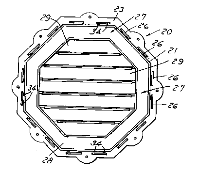
FIG. 3 is a plan view of the plastic product embodying
the invention with the flange members removed.
FIG. 4 is a plan view of the flange members, one
flange member being out of position.
lo FIG. ~ is a fragmentary plan view on an enlarged scale
of the plastic base member shown in FIG. 3.
FIG. 6 is a fragment~ry sectional view on an enlarged
scale taken along lines 6-6 in FIG. 5.
FIG. 7 is an exploded view of the portion of the
lS plastic product shown in FI&. 6.
FIG. 8 is a fragmentary sectional on an enlarged scale
of a modified form of the invention.
FIG. 9 is a fragmentary sectional view on an enlarged
scale of another modified form of the invention.

21~198
-
Description of the Preferred Embodiment
Referring to FIGS. 1 and 2, the invention is shown
in connection with use as a louver over an opening in a building.
The plastic building product 20 comprises a plastic body 21 and
a plurality of flange members 22. The body 21 is fastened to
the wall of the building and the flange members 22 ~re provided
there over after the siding S has been applied an~ connected to
the plastic body as presently described.
As shown in FIGS. 3, 4 and 5-8, the plastic body 21
lo includes a base portion 23 which has an opening 24 therein and
spaced integral walls 25, 26 that extend at a right angle to
the base 23. Wall 25 defines an integral continuous wall with
the base herein shown as octagonal. The wall can be round,
triangular or any other annular shape. The outer wall 26 is in
the form of segments spaced from one another, herein shown as
two segments along each side of the octagon. The plastic product
21 further includes an integral front wall 27 that has a
continuous ~eriphery extending from the outer edge of the wall
25 and integral louvers 29 which are parallel to one another in
the front wall 25.
Referring to FIGS. 4, 6 and 7, each flange segment
22 includes an inner wall 30 and outer wall 31 which are connected
to one another by an integral transverse wall 32. The inner
wall 30 is adapted to extend in the space 33 between the walls
25 and wall segments 2Ç and be held in position thereon by one
or more teeth 34 on the outer surface of the inner wall 25 which
engage one of the axially spaced openings 35 in the wall 30.

21~198
As shown in FIG. 5, the teeth 34 extend into the space 33
adjacent the segments 26.
In use, the plastic body 21 is mounted about the
opening in a building, the siding S is thereafter applied to
abut the wall segments 26 and then the flange members 22 are
telescoped into the spaces 33 to complete the flange. Each
flange member 22 includes surfaces 36 which are shaped abut
complementary surfaces 36 on the adjacent segments 22 to complete
the flange about the ~eriphery plastic body.
o In the modified form shown in Fig. 8, the teeth 34a
are trapezoidal in cross section.
In the form shown in Fig. 9, the axially spaced
openings 35b are in the walls 26, which are more flexible than
continuous inner wall 25, and the tooth 34b is on the outer
surface of the inner wall 30 of the flange segments.
It can thus be seen that there has been provided a
plastic produ-t which has a sectional flange; which can
accommodate siding of different thicknesses; and which is readily
assembled and disassembled.
--5--

Representative Drawing
A single figure which represents the drawing illustrating the invention.
Administrative Status

2024-08-01:As part of the Next Generation Patents (NGP) transition, the Canadian Patents Database (CPD) now contains a more detailed Event History, which replicates the Event Log of our new back-office solution.

Please note that "Inactive:" events refers to events no longer in use in our new back-office solution.

For a clearer understanding of the status of the application/patent presented on this page, the site Disclaimer , as well as the definitions for Patent , Event History , Maintenance Fee  and Payment History  should be consulted.

Event History

Description Date
Inactive: IPC from MCD 2006-03-11
Time Limit for Reversal Expired 2004-07-19
Application Not Reinstated by Deadline 2004-07-19
Deemed Abandoned - Failure to Respond to Maintenance Fee Notice 2003-07-21
Letter Sent 2002-05-30
Inactive: Status info is complete as of Log entry date 2002-05-30
Inactive: Application prosecuted on TS as of Log entry date 2002-05-30
Request for Examination Requirements Determined Compliant 2002-05-01
All Requirements for Examination Determined Compliant 2002-05-01
Application Published (Open to Public Inspection) 1996-01-21

Abandonment History

Abandonment Date Reason Reinstatement Date
2003-07-21

Maintenance Fee

The last payment was received on 2002-07-04

Note : If the full payment has not been received on or before the date indicated, a further fee may be required which may be one of the following

  • the reinstatement fee;
  • the late payment fee; or
  • additional fee to reverse deemed expiry.

Please refer to the CIPO Patent Fees web page to see all current fee amounts.

Fee History

Fee Type Anniversary Year Due Date Paid Date
MF (application, 2nd anniv.) - standard 02 1997-07-21 1997-06-27
MF (application, 3rd anniv.) - standard 03 1998-07-20 1998-07-09
MF (application, 4th anniv.) - standard 04 1999-07-19 1999-07-15
MF (application, 5th anniv.) - standard 05 2000-07-19 2000-07-04
MF (application, 6th anniv.) - standard 06 2001-07-19 2001-07-11
Request for examination - standard 2002-05-01
MF (application, 7th anniv.) - standard 07 2002-07-19 2002-07-04
Owners on Record

Note: Records showing the ownership history in alphabetical order.

Current Owners on Record
MID-AMERICA BUILDING PRODUCTS CORPORATION
Past Owners on Record
CHARLES E. SCHIEDEGGER
Past Owners that do not appear in the "Owners on Record" listing will appear in other documentation within the application.
Documents

To view selected files, please enter reCAPTCHA code :


To view images, click a link in the Document Description column. To download the documents, select one or more checkboxes in the first column and then click the "Download Selected in PDF format (Zip Archive)" or the "Download Selected as Single PDF" button.

List of published and non-published patent-specific documents on the CPD .

If you have any difficulty accessing content, you can call the Client Service Centre at 1-866-997-1936 or send them an e-mail at CIPO Client Service Centre.


Document
Description 
Date
(yyyy-mm-dd) 
Number of pages   Size of Image (KB) 
Representative drawing 1999-08-04 1 15
Abstract 1995-07-19 1 15
Cover Page 1995-07-19 1 16
Description 1995-07-19 5 152
Claims 1995-07-19 3 59
Drawings 1995-07-19 3 73
Reminder - Request for Examination 2002-03-20 1 119
Acknowledgement of Request for Examination 2002-05-30 1 179
Courtesy - Abandonment Letter (Maintenance Fee) 2003-08-18 1 176
Fees 1999-07-15 1 31
Fees 2001-07-11 1 33
Fees 1997-06-27 1 39
Fees 2002-07-04 1 34
Fees 1998-07-09 1 35
Fees 2000-07-04 1 33