Language selection

Search

Patent 2154283 Summary

Third-party information liability

Some of the information on this Web page has been provided by external sources. The Government of Canada is not responsible for the accuracy, reliability or currency of the information supplied by external sources. Users wishing to rely upon this information should consult directly with the source of the information. Content provided by external sources is not subject to official languages, privacy and accessibility requirements.

Claims and Abstract availability

Any discrepancies in the text and image of the Claims and Abstract are due to differing posting times. Text of the Claims and Abstract are posted:

  • At the time the application is open to public inspection;
  • At the time of issue of the patent (grant).
(12) Patent: (11) CA 2154283
(54) English Title: ARRANGEMENT FOR BREEDING POULTRY IN CAGE BATTERIES
(54) French Title: DISPOSITIF POUR L'ELEVAGE DE VOLAILLES EN BATTERIES DE CAGES
Status: Expired and beyond the Period of Reversal
Bibliographic Data
(51) International Patent Classification (IPC):
  • A01K 31/00 (2006.01)
(72) Inventors :
  • KUHLMANN, JOSEF (Germany)
(73) Owners :
  • JOSEF KUHLMANN
(71) Applicants :
  • JOSEF KUHLMANN (Germany)
(74) Agent: SMART & BIGGAR LP
(74) Associate agent:
(45) Issued: 2001-06-05
(86) PCT Filing Date: 1994-01-29
(87) Open to Public Inspection: 1994-09-01
Examination requested: 1997-01-28
Availability of licence: N/A
Dedicated to the Public: N/A
(25) Language of filing: English

Patent Cooperation Treaty (PCT): Yes
(86) PCT Filing Number: PCT/DE1994/000096
(87) International Publication Number: DE1994000096
(85) National Entry: 1995-07-05

(30) Application Priority Data:
Application No. Country/Territory Date
P 43 04 599.5 (Germany) 1993-02-16

Abstracts

English Abstract


The invention relates to a cage battery for poultry
breeding in which the birds are removed by making the actual
grid base of the individual cages or cage sections removable,
ie. it may be rolled up, pulled out or folded up, while
beneath the grid base there is a conveyor belt capable of
removing the birds from the barn.


Claims

Note: Claims are shown in the official language in which they were submitted.

THE EMBODIMENTS OF THE INVENTION IN WHICH AN EXCLUSIVE
PROPERTY OR PRIVILEGE IS CLAIMED ARE DEFINED AS FOLLOWS.
1. Arrangement for breeding poultry in cage bat-
teries (I), having a grid base (8), which is formed by a
flexible netting (9), is subdivided, seen in the longi-
tudinal axis of each rows of cages (2, 3, 4), into indi-
vidual sections (A, B, C) which are independent of one
another and follow one another, and excrement collecting
devices arranged beneath each row of cages (2, 3, 4),
characterized in that the excrement collecting device is
designed as a conveyor belt (5, 6, 7) circulating in the
longitudinal axis of the rows of cages (2, 3, 4), and the
grid base (8) of each section (A, B, C) can be folded
together from outside the cages allowing it to be
actuated such that it exposes the conveyor belt (5, 6, 7)
lying beneath.
2. Arrangement according to claim 1, characterized
in that the grid base (8) can be folded together
transversely with respect to the longitudinal axis of the
rows of cages (2, 3, 4) or of the respective conveyor
belt (5, 6, 7).
3. Arrangement according to claim l or 2, character-
ized in that the grid base (8) can be rolled up.
4. Arrangement according to one of the preceding
claims, characterized in that the conveyor belt (5, 6, 7)
serves as an excrement conveyor belt and, during the
opening of the grid base (8), as an animal conveyor belt.
5. Arrangement according to one of the preceding
claims, characterized by a handle (10), which leads from
an actuation side outside the cage to an opposite last
carrier (11) of the grid base section (A, B, C) and is
connected to the latter.
6. Arrangement according to one of the preceding
claims, characterized in that the grid base (8) is formed
by a plastic netting (9) which rests on spaced-apart
carriers (11) and is connected to the carriers by press

bars (12).
7. Arrangement according to one of the preceding
claims, characterized in that at the delivery ends of the
conveyor belts (5, 6, 7) there are provided transporting
belts (29, 30, 31) for the animals, these transporting
belts (29, 30, 31) comprising roller chains (32) which
are guided in guides and bear support rods (33) which are
arranged at a distance from one another and are aligned
transversely with respect to the longitudinal direction
of the transporting belt.
8. Arrangement according to one of the preceding
claims, characterized in that the individual cages (25,
26) are separated off from one another by separating
walls (21) in which there are provided through-openings
(27), through which the animals can wander from one cage
(25) to the other cage (26) or vice versa.

Description

Note: Descriptions are shown in the official language in which they were submitted.


~ ~s ~l a~3
"Arrangement for breeding noultry in cage batteries"
The invention relates to an arrangement for
breeding poultry as classified in the precharacterizing
clause of the main claim.
It is customary nowadays to breed, i.e. to
fatten, poultry, for example so-called fattening chickens
or broilers, in cage batteries, said poultry being
removed from these cages and sent to a slaughter house
when they reach the so-called "slaughtering weight".
The classification - defining GB-21 03 915 A
discloses a breeding battery in which the grid base
comprises a plastic netting which is flexible and
consequently adapts well to the animal's body. This grid
base is divided into individual sections, which can be
connected one behind the other in the longitudinal axis
of the rows of cages and can be moved out of the cage by
means of a drive, and it is hoped that, with appropriate
forward movement of the individual grid bases, the
chickens can then be removed at the end of the row of
cages. However, the chickens grip the grid base with
their claws and removal of the chickens is possible only
with the risk of injuring the chickens. This known
arrangement thus does not represent a solution to the
problem as to how the removal of the animals from a barn
can be performed without spending considerable time and
without the risk of injury to the animals.
NL-A-71 09 684 discloses the provision of a
circulating conveyor belt, which is designed as an
excrement conveyor belt, beneath grid bases in cage
batteries. Between the underside of the grid bases and
the upper side of the excrement conveyor belt there is
formed a transporting space. The grid bases can in this
case be moved into an open position, whereby the animals
on these bases are forced to fall into the transporting
space lying beneath. According to the proposal correspon-
ding to NL-A-71 09 684, the grid bases are swivelled
i~.~h

ads ~~~3
_ la -
about an axis running parallel with respect to the
longitudinal axis of the excrement conveyor belts.
In an arrangement according to DE-A-24 33 584,
the exposure of the excrement conveyor belt is performed
by pulling out the grid bases through the openings of the
cage doors.
According to SU-A-14 77 343, the establishing of
the connection between cage base and excrement conveyor
belt lying beneath is likewise performed by pulling out
the cage bases..
These devices, known for many years, have not
proven successful in practice, since on the one hand the
space for the cage bases to be pulled out is not
available, on the other hand the animals grip with their
claws on the bases when pulling out the bases or
swivelling the bases and can be brought onto the conveyor
belts lying beneath only with difficulty.
The invention is thus based on the object of
simplifying the operation of removal from a barn and
ensuring that the transfer of the animals from the actual
cage base to the conveyor belt is made possible without
the risk of injury to the animals.
This object on which the invention is based is
achieved by the teaching of the main claim.
Advantageous developments are explained in the
subclaims.
The invention essentially relates to an apparatus
for removing fattening chickens or broilers from a barn,
the removal operation being simplified in that the base,
designed in a way known per se as a grid, of the individ
ual cages can be folded together, so that the animals
fall from the grid base which was there onto a conveyor
belt located beneath. It has been shown, surprisingly
that when the grid base is folded together the animals do
not hold tight but voluntarily jump on to the conveyor
belt located beneath. Since the distance from the grid
base to the conveyor belt is not very great, this does
not cause any great disturbance in the cage, and it is

CA 02154283 2000-10-30
- 2 -
then possible to convey the animals out of the rows
of cages by the conveyor belt, otherwise serving as
an excrement conveyor belt. It goes without saying
that beforehand the excrement conveyor belt is cleared
of the excrement otherwise on it. Since the excrement
conveyor belt is usually designed as a solid-surface
belt and not as a grid belt, like the actual grid
base, the animals cannot grip onto the excrement
conveyor belt and are thus delivered at the
delivery point of the excrement conveyor belt in a very
simple way from this belt onto a further-conveying belt,
which, according to a further feature of the invention,
preferably comprises two mutually parallel arranged
guides for roller chains which bear support rods which
are arranged at a distance from one another and are
aligned transversely with respect to the longitudinal
direction of the transporting belt.
Such an apparatus, taken as itself, is known from
DE-38 00 817 C1.
According to the subclaims, various measures to
remove the grid base are proposed, for example the grid
base can be rolled up, it can be pulled out to the front
or rear or it can, as is explained subsequently in the
exemplary embodiment, be pushed together inside the cage,
so that as a result the chickens fall through downwards
onto the excrement conveyor belt.
An exemplary embodiment of the invention is
explained below with reference to the drawings. In the
drawings:
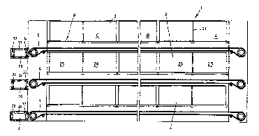
Fig. 1 shows entirely schematically the arrangement of
a cage battery, seen transversely with respect to
the longitudinal axis of the rows of cages,
Fig. 2 shows a schematic representation of the cage
battery, but now in the longitudinal axis of the

-15~ 2 ~ 3
WO 94/18823 - 3 - PCT/DE94/00096
rows of cages,
Fig. 3 shows on an enlarged scale the design of the grid
base, including handle, and
Fig. 4 shows a diagrammatic representation of a cage
section.
In the drawings, 1 denotes a cage battery which
comprises the individual rows of cages 2, 3 and 4,
arranged one above the other. The individual cages of the
rows of cages 2, 3 and 4 are bounded on their underside
by a grid base 8. Beneath the grid base 8 there runs for
each row of cages 2, 3 and 4 in each case a conveyor belt
5, 6 or 7, which normally conveys away to the outside the
excrement falling through the grid base of the animals
kept in the cages of the rows of cages 2, 3 and 4.
The individual grid bases of each row of cages 2,
3 and 4 are designed as individual sections A, B and C,
which follow one another, seen in the longitudinal axis
of the rows of cages, which can be handled independently
of one another. While in the case of the arrangement
represented in Fig. 1, one section of a grid base 8
serves for two cages 25, 26, seen in the longitudinal
axis of the rows of cages or of the conveyor belt, it is
of course possible to equip more cages with a grid base
section A, B or C or to provide such a grid base section
A, B or C for each individual cage (Fig. 4).
The actual grid base 8 comprises a plastic
netting 9, which rests on a carrier 11, it being so in
the case of the exemplary embodiment represented in
Figs 3 and 4 that the carriers run parallel with respect
to the longitudinal axis of the conveyor belt 5 and
consequently parallel with respect to the row of cages 2.
Individual separating walls 21 between the cages 25 and
26 adjoin, as is illustrated in Fig. 3, the upper side of
the actual grid base 8 via a guard wall 22. This reliably
eliminates injuries to the animals when the grid base 8
is actuated. In these separating walls 21, separating off
the individual cages 25 and 26, there are provided - as
Fig. 3 illustrates - through-openings 27, which permit
communication of the animals between the individual

~~54~.83
WO 94/18823 - 4 - PCT/D894/00096
cages, so that animals can Wander from one cage to the
other.
The plastic netting 9 is fixed on the carriers 11
by means of press bars 12, which act like pushbuttons,
the locking-in parts 28 of the press bars 12, which parts
engage in the carriers 11, being subdivided, however,
such that it is not necessary to interrupt the actual
plastic netting 9 completely in the 'region of the
carriers 11 and the press bars 12, but instead the
locking-in parts 28 of the press bars 12 pass through the
openings of the grid base 8 of the plastic netting, while
the upper side [sic] of the press bars 12 are continuous.
Acting on the last carrier 11, situated on the
left [sic] in Fig. 3, is a handle 10, which substantially
comprises a draw bar 23 and a grip 24, it being possible
for the draw bar 23 - as is evident in Fig. 3 - to be,
for example, screwed, welded or hooked on the last
carrier 11.
If the grip 24 is then moved to the right in the
representation in Fig. 3, the grid base 8, that is to say
the plastic netting 9 and the carriers 11, is folded
together, and the individual carriers 11 come to bear
against one another, as is represented in Fig. 2. Here,
in the upper region of Fig. 2, the actual grid base 8 is
represented in its position of rest,. so that therefore
animals can stand on here, while in the two rows of cages
2 and 3 situated beneath the grid base 8 is folded
together, so that then the animals otherwise on the grid
base 8 pass onto the respectively assigned conveyor belt
5, 6 or 7.
By actuating the handle 10 for the individual
grid base sections A, B and C, easy removal from the barn
of the animals otherwise standing on the grid bases 8 is
then possible. The animals then passing onto the conveyor
belt 5, 6 or 7 after removal of the grid base 8 can be
carried out by movement of the conveyor belt, there then
being provided, according to Figs. 1 and 2, in the
delivery region of the conveyor belt transporting belts
29, 30 and 31. These transporting belts substantially

2~.5~~$,~
WO 94/18823 - 5 - PCT/DB94/00096
comprise two roller chains 32, between which support rods
33 are interposed transversely with respect to the
conveying direction of each transporting belt. Such
transporting belts are generally known for the conveyance
of eggs in chickens farms.
The animals coming from the solid-surface and
smooth conveyor belts 5, 6 and 7 are pleased to come onto
the support rods 33, which allow very much their natural
urge to grip with the claws of their feet. As a result,
troublefree transferring of the animals from the conveyor
belts 5, 6 and 7 onto the conveyor belts 29, 30 and 31 is
possible.
In the case of the representation in Figs. 3 and
4, a feeding trough 14 can be seen and in Fig. 4 the
ventilation line 34.

Representative Drawing
A single figure which represents the drawing illustrating the invention.
Administrative Status

2024-08-01:As part of the Next Generation Patents (NGP) transition, the Canadian Patents Database (CPD) now contains a more detailed Event History, which replicates the Event Log of our new back-office solution.

Please note that "Inactive:" events refers to events no longer in use in our new back-office solution.

For a clearer understanding of the status of the application/patent presented on this page, the site Disclaimer , as well as the definitions for Patent , Event History , Maintenance Fee  and Payment History  should be consulted.

Event History

Description Date
Time Limit for Reversal Expired 2012-01-30
Letter Sent 2011-01-31
Inactive: Office letter 2006-08-29
Inactive: Corrective payment - s.78.6 Act 2006-07-28
Inactive: Entity size changed 2002-10-25
Grant by Issuance 2001-06-05
Inactive: Cover page published 2001-06-04
Pre-grant 2001-03-05
Small Entity Declaration Determined Compliant 2001-03-05
Inactive: Final fee received 2001-03-05
Letter Sent 2000-11-30
Notice of Allowance is Issued 2000-11-30
Amendment Received - Voluntary Amendment 2000-10-30
Inactive: Office letter 2000-08-07
Inactive: Approved for allowance (AFA) 2000-07-28
Amendment Received - Voluntary Amendment 1998-12-04
Inactive: Application prosecuted on TS as of Log entry date 1998-05-12
Inactive: Status info is complete as of Log entry date 1998-05-12
All Requirements for Examination Determined Compliant 1997-01-28
Request for Examination Requirements Determined Compliant 1997-01-28
Application Published (Open to Public Inspection) 1994-09-01

Abandonment History

There is no abandonment history.

Maintenance Fee

The last payment was received on 2001-01-12

Note : If the full payment has not been received on or before the date indicated, a further fee may be required which may be one of the following

  • the reinstatement fee;
  • the late payment fee; or
  • additional fee to reverse deemed expiry.

Patent fees are adjusted on the 1st of January every year. The amounts above are the current amounts if received by December 31 of the current year.
Please refer to the CIPO Patent Fees web page to see all current fee amounts.

Fee History

Fee Type Anniversary Year Due Date Paid Date
Request for examination - small 1997-01-28
MF (application, 4th anniv.) - standard 04 1998-01-29 1998-01-06
MF (application, 5th anniv.) - standard 05 1999-01-29 1998-12-17
MF (application, 6th anniv.) - small 06 2000-01-31 1999-12-13
MF (application, 7th anniv.) - small 07 2001-01-29 2001-01-12
Final fee - small 2001-03-05
MF (patent, 8th anniv.) - standard 2002-01-29 2001-10-31
MF (patent, 9th anniv.) - standard 2003-01-29 2002-10-17
Reversal of deemed expiry 2004-01-29 2003-11-13
MF (patent, 10th anniv.) - standard 2004-01-29 2003-11-13
MF (patent, 11th anniv.) - standard 2005-01-31 2005-01-07
MF (patent, 12th anniv.) - standard 2006-01-30 2005-11-08
2006-07-28
MF (patent, 13th anniv.) - standard 2007-01-29 2006-10-23
MF (patent, 14th anniv.) - standard 2008-01-29 2008-01-16
MF (patent, 15th anniv.) - small 2009-01-29 2009-01-15
MF (patent, 16th anniv.) - small 2010-01-29 2010-01-19
Owners on Record

Note: Records showing the ownership history in alphabetical order.

Current Owners on Record
JOSEF KUHLMANN
Past Owners on Record
None
Past Owners that do not appear in the "Owners on Record" listing will appear in other documentation within the application.
Documents

To view selected files, please enter reCAPTCHA code :


To view images, click a link in the Document Description column. To download the documents, select one or more checkboxes in the first column and then click the "Download Selected in PDF format (Zip Archive)" or the "Download Selected as Single PDF" button.

List of published and non-published patent-specific documents on the CPD .

If you have any difficulty accessing content, you can call the Client Service Centre at 1-866-997-1936 or send them an e-mail at CIPO Client Service Centre.


Document
Description 
Date
(yyyy-mm-dd) 
Number of pages   Size of Image (KB) 
Description 1996-01-07 7 320
Claims 1996-01-07 2 69
Description 1994-08-31 8 316
Abstract 1994-08-31 1 10
Claims 1994-08-31 2 66
Drawings 1994-08-31 4 187
Description 2000-10-29 6 265
Representative drawing 2001-05-08 1 12
Representative drawing 1999-05-30 1 20
Commissioner's Notice - Application Found Allowable 2000-11-29 1 165
Maintenance Fee Notice 2011-03-13 1 170
International preliminary examination report 1995-07-04 24 767
Correspondence 2000-08-06 2 14
Correspondence 2001-01-11 1 25
Correspondence 2001-03-04 2 50
Fees 2001-10-30 1 40
Fees 2001-01-11 1 42
Correspondence 2006-08-28 1 14
Fees 2006-10-22 1 35
Fees 1997-01-13 1 40
Fees 1995-11-15 1 44