Language selection

Search

Patent 2154369 Summary

Third-party information liability

Some of the information on this Web page has been provided by external sources. The Government of Canada is not responsible for the accuracy, reliability or currency of the information supplied by external sources. Users wishing to rely upon this information should consult directly with the source of the information. Content provided by external sources is not subject to official languages, privacy and accessibility requirements.

Claims and Abstract availability

Any discrepancies in the text and image of the Claims and Abstract are due to differing posting times. Text of the Claims and Abstract are posted:

  • At the time the application is open to public inspection;
  • At the time of issue of the patent (grant).
(12) Patent: (11) CA 2154369
(54) English Title: OPTICAL FIBRE PREFORMS
(54) French Title: PREFORMES A FIBRES OPTIQUES
Status: Term Expired - Post Grant Beyond Limit
Bibliographic Data
(51) International Patent Classification (IPC):
  • C03B 37/012 (2006.01)
(72) Inventors :
  • INCE, PETER ROBERT (United Kingdom)
  • WOOD, GRAHAM FREDERICK (United Kingdom)
  • SAMPSON, PETER CHARLES (United Kingdom)
(73) Owners :
  • PRYSMIAN CABLES & SYSTEMS LIMITED
(71) Applicants :
  • PRYSMIAN CABLES & SYSTEMS LIMITED (United Kingdom)
(74) Agent: SMART & BIGGAR LP
(74) Associate agent:
(45) Issued: 2000-04-04
(22) Filed Date: 1995-07-20
(41) Open to Public Inspection: 1996-01-22
Examination requested: 1997-10-15
Availability of licence: N/A
Dedicated to the Public: N/A
(25) Language of filing: English

Patent Cooperation Treaty (PCT): No

(30) Application Priority Data:
Application No. Country/Territory Date
9414751 (United Kingdom) 1994-07-21

Abstracts

English Abstract

A method of manufacturing a preform for drawing into an optical fibre comprises positioning a rod 10 within a sleeving tube 42 therefor to form an assembly in which there is an annular space 26 between the rod and tube, and collapsing the tube onto the rod to form a solid cross-section preform. The collapsing step comprises sealingly closing the annular space 26 at one end 30 of the assembly and applying suction to the annular space from the other end of the assembly. The annular space 26 at said one end 30 is sealingly closed by locating the end 28 of the tube at said one end on an annular rib 22 of said rod and fusing said tube end to said rib.


French Abstract

Une méthode de fabrication d'une préforme à tirer dans une fibre optique comprend le positionnement d'une tige 10 dans une gaine isolante 42 pour former un ensemble dans lequel il y a un espace annulaire 26 entre la tige et la gaine et l'affaissement de la gaine sur la tige pour former une préforme à section transversale pleine. L'étape d'affaissement comprend la fermeture étanche de l'espace annulaire 26 à une extrémité 30 de l'ensemble et l'application d'une aspiration à l'espace annulaire à partir de l'autre extrémité de l'ensemble. L'espace annulaire 26 à ladite extrémité 30 est fermé de manière étanche en plaçant l'extrémité 28 de la gaine à ladite extrémité sur une nervure annulaire 22 de ladite tige et en fusionnant ladite extrémité de gaine à ladite nervure.

Claims

Note: Claims are shown in the official language in which they were submitted.

THE EMBODIMENTS OF THE INVENTION IN WHICH AN EXCLUSIVE
PROPERTY OR PRIVILEGE IS CLAIMED ARE DEFINED AS FOLLOWS:
1. A method of manufacturing a preform for drawing
into an optical fibre comprising providing a rod for forming
at least a core portion of the optical fibre to be drawn from
the preform, said rod extending between opposite ends thereof
and having a solid cross-section; providing a sleeving tube
for the rod for forming at least a cladding portion of the
optical fibre to be drawn from the preform, said tube having a
length between opposite ends thereof which is substantially
the same as the length of the rod between the opposite ends of
the rod; positioning said rod within said sleeving tube
therefor to form an assembly in which the rod and tube extend
coextensively between opposite ends of the assembly with an
annular space between the rod and tube and with one end of the
tube and one end of the rod being disposed at one end of the
assembly; and collapsing the tube onto the rod to form a solid
cross-section preform, said collapsing step comprising
sealingly closing said annular space at said one end of said
assembly and applying suction to the annular space from the
other end of said assembly, wherein said annular space at said
one end is sealingly closed by locating said one end of the
tube at said one end of the assembly on an annular rib of said
rod and fusing said tube end to said rib.
2. A method as claimed in claim 1, wherein said one
end of said tube has a radially inner edge which is engaged
-8-

with said rib.
3. A method as claimed in claim 1, wherein said fusing
step comprises heating said tube at a position which is
axially inward of said rib from said one end of the assembly
and thereafter heating said tube at a position which is
axially aligned with said rib.
4. A method as claimed in claim 1, including forming
said annular rib of said rod by heating said rod at a
predetermined axial position therealong and axially
compressing said rod.
5. A method as claimed in claim 4, wherein said rod is
rotated about its central axis during said step of forming
said annular rib thereof.
6. A method as claimed in claim 1, wherein said rod is
monolithic.
7. A method as claimed in claim 1 wherein said rod is
a glass rod and said tube is a glass tube, the glass of said
rod having a refraction index different from the refraction
index of said tube.
-9-

Description

Note: Descriptions are shown in the official language in which they were submitted.


215 ~~sg
. 1
This invention relates to a method of
manufacturing a preform for drawing into an optical
fibre.
It is known to manufacture such a preform by
positioning a rod within a sleeving tube therefor to
form an assembly in which there is an annular space
between the rod and tube and collapsing the tube onto
the rod to form a solid cross-section tube. Such a
method is sometimes referred to as the 'rod-in-tube'
method and methods falling into this, category are
disclosed for example in GB2109367A and GB2043619A.
The collapsing step in the rod-in-tube method
typically comprises sealingly closing the annular
space between the rod and tube at one end of the
assembly and applying suction to the annular space
from the other end of the assembly. Typically the
collapsing step also includes thermally softening the
tube for example using a heat source which traverses
the assembly from said one end to the other end and
also the sealing of the annular space at said one end
of the assembly has been achieved by a sealing device
comprising elastomeric 'O'-rings sealing against
surfaces of the rod and tube at axially spaced
locations. Such an arrangement is disadvantageous in

~~154 egg
that not only is the axial length of the assembly over which
the sealing device extends not collapsed thus shortening the
length of the preform, but also because when a heat source is
used there is a danger that the material of the 'O'-rings will
degrade and that degradation products will be sucked along the
annular space between the rod and tube during the collapsing
step to contaminate the interface therebetween. Such
contamination can result in flaws at the interface which give
rise to breaks in the fibre drawn from the preform during the
tensile testing. In an attempt to avoid this latter problem
the traverse of the heat source may be started at a
predetermined distance from the '0'-rings, but this further
shortens the resulting preform.
In order to avoid the above-mentioned problem in
broad terms the method of the present invention seals the
material of the rod and tube together at said one end.
More specifically, the invention provides a method
of manufacturing a preform for drawing into an optical fibre
comprising providing a rod for forming at least a core portion
of the optical fibre to be drawn from the preform, said rod
extending between opposite ends thereof and having a solid
cross-section; providing a sleeving tube for the rod for
forming at least a cladding portion of the optical fibre to be
drawn from the preform, said tube having a length between
opposite ends thereof which is substantially the same as the
length of the rod between the opposite ends of the rod;
positioning said rod within said sleeving tube therefor to
form an assembly in which the rod and tube extend
- 2 -
67487-491

coextensively between opposite ends of the assembly with an
annular space between the rod and tube and with one end of the
tube and one end of the rod being disposed at one end of the
assembly; and collapsing the tube onto the rod to form a solid
cross-section preform, said collapsing step comprising
sealingly closing said annular space at said one end of said
assembly and applying suction to the annular space from the
other end of said assembly, wherein said annular space at said
one end is sealingly closed by locating said one end of the
tube at said one end of the assembly on an annular rib of said
rod and fusing said tube end to said rib.
The invention also includes a preform when
manufactured by the method defined in the last preceding
paragraph and an optical fibre drawn from such a preform.
In the method, preferably said tube end is located
on said rib with the radially inner edge of said tube end
engaging said rib.
The fusing step may comprise initially heating said
tube at a position which is axially inwardly of said rib from
said one end of the assembly and thereafter heating said tube
at a position which is axially aligned with said rib.
The method may include forming said annular rib of
said rod by heating said rod at a predetermined axial position
therealong and axially compressing said rod, and preferably
said rod is rotated about its central axis during said step of
forming said annular rib thereof.
In order that the invention may be well
- 3 -
67487-491

_215369
4
understood, an embodiment thereof which is given by
way of example only, will now be described with
reference to the accompanying drawings, in which:
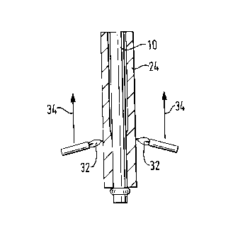
Figure 1 schematically illustrates the step of
forming a rod with an annular rib;
Figure 2 schematically illustrates the
positioning of the rod within a sleeving tube therefor
to form an assembly;
Figure 3 schematically illustrates the step of
fusing an end of the tube to the rib; and
Figure 4 schematically illustrates the step of
collapsing the tube onto the rod.
In its simplest form the rod used in the
embodiment is a silica rod doped with a refractive
index raising dopant and the sleeving tube is formed
of substantially pure silica whereby when the preform
is drawn into an optical fibre the rod forms the
optical fibre core and the tube forms the cladding.
However it is to be understood that the rod and/or the
tube may have layers with different dopants or dopant
concentrations and that accordingly a radially outer
annular portion of the rod may form part of the
cladding and a radially inner annular portion of the
tube may form part of the core. The rod may be made
using an inside vapour deposition technique such as
the modified chemical vapour deposition technique or

21~~~~9
an outside vapour deposition technique.
Referring now to the drawings, as shown in Figure
l, the rod, which is designated 10 in the Figures, is
heated by flames 12 or another suitable heat source at
5 a predetermined axial position 14 therealong adjacent,
but spaced from, one end 16 thereof, whilst being
axially compressed and rotated about its axis as
indicated by arrows 18 and 20 respectively in order to
form an annular rib, or protuberance, 22 on the rod.
The rod 10 is then positioned within the sleeving tube
24 to form an assembly as illustrated in Figure 2 in
which there is an annular space 26 (shown enlarged for
the sake of clarity) between the rod and tube and an
end 28 of the tube locates on the rib 22 at one end 30
of the assembly. As shown, the tube end 28 is located
on the rib 22 with the radially inner edge 31 of the
tube end 28 engaging the rib 22. The end 16 of the
rod is clamped in the bottom chuck of a vertical lathe
(not shown) and the relative positions of the rod and
tube are adjusted and clamped at the other end of the
assembly by a known device (not shown) associated with
the upper chuck of the lathe in order to locate the
rod concentrically with the tube.
Then as shown in Figure 3 the tube end 28 is
fused to the rib 22 to seal the annular space 26 at
the end 30 of the assembly. The fusing step comprises

6
initially heating the tube with flames 32 or another
suitable heat source at a position 33 which is axially
inwardly of the rib 22 from the end 30 of the assembly
and thereafter at a position which is axially aligned
with the rib, both heating steps being carried out
whilst the assembly is rotated in the lathe.
Typically the flames 32 initially heat the tube about
1 cm above the tube end 28 for about 60 seconds after
which the flames are moved downwardly into axial
alignment with the interface between the tube end and
the rib for about 60 seconds, suction being applied
for about the last 30 seconds of this period to the
annular space 26 from the top end of the assembly via
the clamping device which also seals the annular space
and provides a suitable connection to a suction
device. In this way the rod and sleeve are sealed
together at the end 30 thereof and suction is applied
to the annular space.
Thereafter, as schematically shown in Figure 4 by
arrows 34, the flames 32 are traversed upwardly along
the assembly from the initial heating position axially
inwardly of the rib referred to above to collapse the
tube onto the rod in the normal manner to form a solid
cross-section preform.
From the foregoing it will be appreciated that
the described method of sealing the annular space

_215~3~~
between the tube and rod at the end of the assembly
remote from the end to which suction is applied
results in a longer usable preform from an assembly of
a given length than is achievable using the prior
sealing device discussed above and furthermore
eliminates the risk of contamination at the rod-tube
interface due to degradation of the '0'-rings of such
a device.

Representative Drawing
A single figure which represents the drawing illustrating the invention.
Administrative Status

2024-08-01:As part of the Next Generation Patents (NGP) transition, the Canadian Patents Database (CPD) now contains a more detailed Event History, which replicates the Event Log of our new back-office solution.

Please note that "Inactive:" events refers to events no longer in use in our new back-office solution.

For a clearer understanding of the status of the application/patent presented on this page, the site Disclaimer , as well as the definitions for Patent , Event History , Maintenance Fee  and Payment History  should be consulted.

Event History

Description Date
Inactive: Expired (new Act pat) 2015-07-20
Letter Sent 2009-09-23
Grant by Issuance 2000-04-04
Inactive: Cover page published 2000-04-03
Inactive: Final fee received 1999-12-23
Pre-grant 1999-12-23
Notice of Allowance is Issued 1999-11-05
Letter Sent 1999-11-05
Inactive: Approved for allowance (AFA) 1999-10-04
Inactive: RFE acknowledged - Prior art enquiry 1998-01-20
Inactive: Status info is complete as of Log entry date 1998-01-20
Inactive: Application prosecuted on TS as of Log entry date 1998-01-20
Request for Examination Requirements Determined Compliant 1997-10-15
All Requirements for Examination Determined Compliant 1997-10-15
Application Published (Open to Public Inspection) 1996-01-22

Abandonment History

There is no abandonment history.

Maintenance Fee

The last payment was received on 1999-07-05

Note : If the full payment has not been received on or before the date indicated, a further fee may be required which may be one of the following

  • the reinstatement fee;
  • the late payment fee; or
  • additional fee to reverse deemed expiry.

Please refer to the CIPO Patent Fees web page to see all current fee amounts.

Owners on Record

Note: Records showing the ownership history in alphabetical order.

Current Owners on Record
PRYSMIAN CABLES & SYSTEMS LIMITED
Past Owners on Record
GRAHAM FREDERICK WOOD
PETER CHARLES SAMPSON
PETER ROBERT INCE
Past Owners that do not appear in the "Owners on Record" listing will appear in other documentation within the application.
Documents

To view selected files, please enter reCAPTCHA code :


To view images, click a link in the Document Description column. To download the documents, select one or more checkboxes in the first column and then click the "Download Selected in PDF format (Zip Archive)" or the "Download Selected as Single PDF" button.

List of published and non-published patent-specific documents on the CPD .

If you have any difficulty accessing content, you can call the Client Service Centre at 1-866-997-1936 or send them an e-mail at CIPO Client Service Centre.


Document
Description 
Date
(yyyy-mm-dd) 
Number of pages   Size of Image (KB) 
Abstract 1996-01-22 1 18
Cover Page 1996-03-13 1 16
Description 1998-02-16 7 227
Claims 1998-02-16 2 66
Description 1996-01-22 7 206
Claims 1996-01-22 2 43
Drawings 1996-01-22 1 22
Cover Page 2000-02-04 1 30
Representative drawing 2000-02-04 1 5
Representative drawing 1998-04-21 1 6
Acknowledgement of Request for Examination 1998-01-20 1 173
Commissioner's Notice - Application Found Allowable 1999-11-05 1 164
Correspondence 1999-12-23 1 38
Correspondence 1995-09-14 3 101