Note: Descriptions are shown in the official language in which they were submitted.
2154S~ 4
Transport and storaqe sYstem
The invention pertains to a transport and storage system in
accordance with the general terms mentioned in Claim l.
With the coming into force of the Packaging Law and
international efforts to reduce, reuse and recycle packing and
associated materials, the requirements made of transport and
storage systems, for example pallets and containers or boxes,
have changed drastically.
Industry and business now increasingly demand pallets and
containers with a long life-span that can be reused for the
user's purposes; moreover, the optimization of space, weight
and material is being demanded. In addition, it should be
possible to manufacture the pallets and containers in varying
shapes and sizes to exact specifications of dimensions, weight
and form, they should be easy to repair and clean, and be
collapsible or foldable for return transport purposes.
A transport and storage system according to the general terms
of Claim l in the form of a flat pallet is known from DE-C-31
38 349. Transport and storage systems of this type are
composed of extruded longitudinal and lateral supports,
particularly of aluminum for applications in areas with high
hygienic requirements. The longitudinal supports consist of
three individual components that can be connected to each
other. The upper component, which forms the supporting
section, is equipped with a connecting device in the form of
two shoulders which border an opening into which the lateral
supports can be inserted.
A disadvantage of this type of transport and storage system
lies in the fact that the packaged goods are not protected at
the bottom, because the number of spaced lateral supports make
it impossible to form a single loading surface. Because of
these conditions, cavities are created in the longitudinal
- 21~554
supports, since the lateral supports are inserted into the
longitudinal supports at spaced distances.
In addition, it is necessary, in the case of transport and
storage systems of this type, to provide openings for forklift
trucks in the sidewalls of the longitudinal supports. These
openings also create hollow areas which collect dust and dirt
and are difficult or impossible to clean.
Similar problems occur in another system known from US-A-
3,954,067.
The object of this invention is, therefore, to create a
transport and storage system of the type described in the
general terms of Claim l, which can be manufactured
economically and which specifically enables the requirements
relating to hygiene, variability and stability to be met.
The means for attaining the object of the invention is
provided by the characteristics of Claim l.
The transport and storage system in accordance with the
invention, which advantageously allows for a modular
constructed unitary design making use of light metal alloy
profile sections, meets the requirements of industry and
businesses as detailed above and even exceeds these in part.
Height, length, width, configuration and carrying capacity of
the transport and storage system can be adapted to individual
requirements as desired.
Cleaning and repair can be done easily and economically, owing
to the smooth and closed surfaces and to the problem-free
collapsibility which can be carried out anytime.
The system in accordance with the invention is particularly
suitable for air cargo and clean rooms, has a long lifespan
and is easy to keep clean and repair when it is in use.
215~S5~
Moreover, there is an option of integrating additional
expansions and modifications, such as hand holds, rollers,
container or lattice box structures, eyebolts and similar
items.
In the transport and storage system according to the
invention, a pallet deck can be used initially as the goods
holding device, consisting of two panels connected by a
connecting profile section and which is open at its outer
edges. In this embodiment, the clamping and sealing channel of
the connecting device takes over the clamping and sealing
function, because the open outer edges are covered all around.
Simultaneously, this of course results in the creation of a
protective edge.
As an alternative to this, it is possible to use a solid
panel, i.e. a component that is not hollow, for the pallet
deck, which also can be inserted into the clamping and sealing
channel. In the case of a solid panel, the edge protection
provided by the clamping and sealing channel in accordance
with the invention stands out primarily, in addition to the
clamping function. If, however, for example, a wooden panel,
preferably a plywood panel, is used, then the sealing function
is also significant, because the clamping and sealing channel
in this case prevents moisture absorption through the
unprotected outer edges owing to the all-round covering of the
edges.
Basically, the above-mentioned types of goods holding devices
can be manufactured of practically any suitable material. The
preferred materials to be used are, however, metal,
particularly aluminum, as well as plastic or wood.
The dependent claims contain advantageous refinements of the
invention.
To create a modular constructed, easily assembled and
21545~4
disassembled transport and storage system in accordance with
this invention that meets the requirements stated in the
preamble, it is possible to design the support device as
individual components connected to each other, preferably in
the form of easily connected profile sections. The footing
sections in particular can be constructed as bar sections
which can be extruded or cast.
Particular preference for the material is given to metal in
the form of a light metal alloy, particularly aluminum.
The sections can be provided with grooves, drilled or punched
openings, into which tongues, nuts or screws can be inserted
which are used to connect the components of the system
according to the invention, thus ensuring easy assembly and
disassembly. If corner connections are required to form the
clamping and sealing channel extending around all the edges of
the goods holding device, these can be provided by gusset
plates, angle sections, plug connection designs, detent
designs, brackets, rivets, threaded connections or welded
connections, if necessary.
Should, in a specific instance, arrangements be required to
seal open ends, for example of footing or skid profile
sections which are open at one end, then can these be made by
inserting end plates.
In principle, it is possible to provide the transport and
storage system according to the invention with a support
device designed as one piece, which in a specially preferred
embodiment consists of a skid base section, a support footing
section and a support section. In a particularly advantageous
embodiment this results in a double T-beam, on top of which,
in the assembled state, the connecting device which forms the
clamping and sealing channel is fitted.
The other basic possible embodiment is a modular constructed
- 21545S~
support device which can be installed and removed, which
consists of at least one footing section and a supporting
member having the clamping and sealing channel . In this
embodiment, as an option, a profile section can be attached to
the footing section as the skid base part.
Both of the embodiments described above can be provided, as
further development stages, with plug-in channels fitted on
the clamping and sealing channel and which allow the erection
of containers in the form of crates or boxes, wherein vertical
panels are inserted into the plug-in channels.
As connection devices for the individual components of the
transport and storage system in accordance with the invention,
consideration is given in principle to screw, clasp, plug and
clamp connections if disassembly is desired. If there is no
such requirement, then welded, adhesive and rivetted
connections are also possible.
All embodiments of the transport and storage system in
accordance with the invention can furthermore be provided with
supplementary equipment, for example in the form of hinge
grooves. Such hinge grooves are, in practice, provided near
the supporting member, preferably as a part of the connecting
device, and permit the attachment for example of handles,
hinged panel sections and the like.
In a particularly advantageous embodiment, the transport and
storage system in accordance with the invention is designed as
a folding container or a collapsible bin. The especially
advantageous embodiment uses the system known as M-folding.
This, first of all, consists of a base plate which, in
accordance with the principles of the invention, is provided
with a goods storage device, for example with a panel-like
pallet deck, whose connecting device has a clamping and
sealing channel extending around all the edges of the goods
holding device. This base unit is provided with a raised edge
`- 2154554
along its outer edges, which outlines a holding area on the
pallet deck, whose height permits the folding of the container
walls, so that it can be fully folded inside the holding area.
On one of the long sides of this raised edge a hinge is
fitted, to which a longitudinal panel, for example the rear
wall of the container, is attached so that it can fold. On the
two short sides of this rear wall, divided side walls are
attached by hinges and these side walls, in turn, are
connected in their centres to each other by hinges. At the end
of both side walls which are facing away from the rear wall, a
front wall is attached parallel to the rear wall by hinges on
its short sides. Finally, a cover section is attached to the
remaining free long side of the rear wall in such a way that
it can move 270. The edges of the side walls and the front
wall which are facing away from the pallet deck are provided
with a ridge of smaller size than the wall thickness, which
engages corresponding grooves in the side walls and the front
wall when these are placed on the raised edges of the pallet
deck to form the container. In this unfolded state, the cover
section can be pivoted by 270 from its opened position, in
which it is flat against the rear wall, to its closed
position, in which it also engages the upper ridges of the
side walls and the front wall with a groove extended on three
sides, so that preferably a dustproof and, in a suitable
embodiment, logically also a waterproof, sealing of the
interior of the container is possible.
In this design it is especially preferably possible for all
the walls and the cover to be constituted by a connecting
device of profile sections, in whose clamping and sealing
channels panels can be inserted, so that the components which
are similar, that is, the front and rear wall and the side
walls can be constructed identically. The cover section
consists of a profile which is identical at the top and bottom
on three edges, so that when the walls are erected, it covers
the interior of the container with one side. On the other
hand, in the folded state, that is, when front, side and rear
_ 21545~4
walls are folded inside the space formed by the raised edges
of the base unit, the other side of the cover covers the
container which has been colIapsed into itself. The side of
the cover facing away from the container at the same time
forms a stacking and locking edge with its upwards profile
section design.
Further details, characteristics and advantages of the
invention result from the following description of exemplary
embodiments based on the drawing.
These show the following:
Fig. 1 a schematically slightly simplified perspective
representation of an embodiment of a transport and
storage system in accordance with the invention;
Fig. 2 a representation of an embodiment of a component of
the support device of the transport and storage
system according to Fig. 1 corresponding to the
illustration in Fig. l;
Figs. 3 to 5 perspective illustrations corresponding to
Figs. 1 and 2 of a second embodiment of the support
device of a transport and storage system;
Figs. 6 and 7 A, B cross-sections of footings of the
support device of the transport and storage system
in accordance with the invention;
Fig. 8 an exploded view of components of the transport and
storage system in accordance with the invention
according to a second preferred embodiment;
Figs. 9 A, B, C a representation of a hinge system in
accordance with the invention which can be handled
as an individual item, particularly for a transport
_ 215~5S~
and storage system in accordance with the invention.
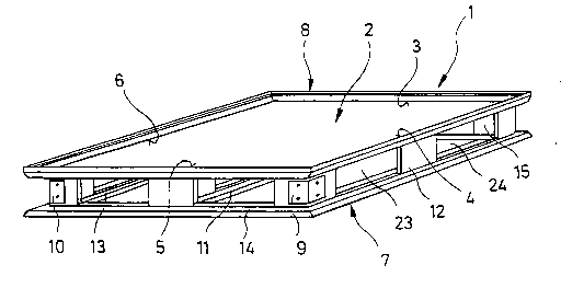
Fig. l illustrates a transport and storage system l in
accordance with the invention in a schematically simplified
representation. The transport and storage system l is in this
example constructed as a flat pallet and is designated as such
hereafter:
The flat pallet l has a goods holding device 2 which in the
case of the example forms the pallet deck. The pallet deck of
the goods holding device 2 has two panels not detailed in Fig.
l, which are connected via a connecting member (e.g. in the
shape of a corrugated profile section) which is also not
detailed further. In an especially advantageous embodiment,
the pallet deck of the goods holding device 2 is manufactured
from aluminum and is constructed in the above-described manner
similar to corrugated cardboard.
These pallet decks are open along the four leading edges 3 to
6. In principle, however, the invention also includes another
pallet deck embodiment, both in its construction and its
selection of material. Particular advantages are obtained in
both cases by the use of a light metal alloy, particularly in
the form of aluminum.
The transport and storage system l in accordance with the
invention as represented by the flat pallet illustrated in
Fig. l, furthermore has a support device 7 which, in the
example, consists of four support members arranged around the
leading edges 3 to 6. One of these support members is
illustrated in Fig. 2. The support device 7 again is provided
with a connecting device 8 to lock the goods holding device 2.
Fig. l illustrates here that the connecting device 8 extends
around all edges 3 to 6 of the goods holding device 2. In this
way, it is possible to lock the goods holding device 2 by
connecting device 8, as well as to close its open edges 3 to
6.
21~554
In addition, Fig. 1 illustrates that the four individual
components of support device 7 which are arranged around the
edges 3 to 6 of goods holding device 2, are connected by
corner modules so as to form a continuous frame, whereby
modules 9 and 10 of the corner modules are visible owing to
the method of illustration selected. Lastly, in the
particularly advantageous embodiment illustrated in Fig. 1,
support device 7 has a fifth support member 11 which is
arranged between the outer support members 12 and 13 and is
connected to support members 14 and 15 in a manner not
illustrated here.
Because all the support members are designed in the same
manner and way, the design of support device 7 being one of
these support members is described below as representative for
all using Fig. 2 .
In the embodiment illustrated in Fig. 2, support member 12 is
depicted as being of one-piece construction. In the example,
it has a longitudinal skid base 16, a footing section 17 which
is arranged perpendicular to the skid base 16 and a supporting
member 18 which again is at a right angle to the footing
section 17. The skid base 16 may be equipped with channels
into which the connecting or covering components or also anti-
skid devices can be inserted. The footing section 17 forms a
supporting footing for support device 7, which by its
attachment to supporting member 18 has connecting device 8 at
its top. Fig. 2 illustrates that connecting device 8 is formed
by two spaced shoulders 19 and 20. In this case, the shoulder
20 is an integral part of supporting member 18. Because of the
connection between supporting member 18 and connecting device
8, this is again connected with skid base 16, thus resulting
in an integrated design. The shoulder 19 is here connected to
supporting member 18 via a perpendicular ridge 20. As
clarified in Fig. 2, ridge 21 projects slightly beyond the
horizontal surface of the ridge 19 and thus forms an edge rail
during assembly as depicted in Fig. 1, which prevents a
21~455~
skidding of the goods arranged on the goods holding device 2.
Ridges 19 and 20 form, as shown in Fig. 2, a clamping and
sealing channel 22. This clamping and sealing channel 22
includes the outer areas of goods holding device 2, as can be
seen in Fig. 1. Thus, while inserting the goods holding device
2 into the clamping and sealing channel 22 in the assembly
position, both a locking as well as a sealing of the open
edges 3 to 6 of goods holding device 2 is achieved.
To assemble the flat pallet 1 illustrated as an example in
Fig. 1, first of all three of the support members of support
device 7 are connected using the corner modules 9 and 10.
Next the goods holding device 2 is inserted into the clamping
and sealing channel 22 now formed along the edges. In order
to be able to close the remaining fourth open edge, a fourth
support member is connected to two of the previously connected
support members, thus creating an all-around frame which can
be seen in Fig. 1, which forms the support device 7 and locks,
stabilizes as well as seals the open edges of the goods
holding device 2. In order to achieve [TR: sic] undesirable
vibration, especially of the unloaded goods holding device 2,
it is possible to choose a slightly conical shape for the
cross-section of the clamping and sealing channel 22, so that
the clamping effect is enhanced. Furthermore, it is possible,
to fit additional seals into clamping and sealing channel 22,
for example in the form of sprayed-on silicon paste, or
inserted sealing and vibration elements. Such sealing and
vibration elements can, for example, be in the form of
U-shaped rubber rings, which surround the edges of goods
holding device 2 and can be inserted into clamping and sealing
channel 22.
In order to make it possible to manipulate a flat pallet 1 in
accordance with Figs. 1 and 2 using manual handling equipment,
the support members are also equipped with openings of which
in Figs. 1 and 2, openings 23 and 24 have been given
- 21~455~
11
representative reference numbers.
Figs. 3 to 5 illustrate an alternative embodiment of support
device 7 of the transport and storage system 1 in accordance
with the invention. This embodiment allows for a modular
construction of the transport and storage system 1, because
support device 7 is not designed as a one-piece profile
section, but has been broken down into its components. Because
these, however, have essentially the same function as in the
embodiment in Fig. 1, the similar components have been given
the same reference numbers below as have been used in Figs. 1
and 2.
Accordingly, Fig. 3 illustrates a supporting member 18 formed
by a profile section, which also has a connecting device 8
with shoulders 19 and 20. The shoulders 19 and 20 again form a
clamping and sealing channel 22, so that this far, reference
may be made to the embodiment in Fig. 2.
In this embodiment the connecting device 8 is fitted with a
plug-in channel 25 on top of shoulder 19. Plug-in channel 25
is defined by two flanges 26 and 27 which are connected to the
outer edge of shoulder 19 in one piece. A fillet 28 is next to
plug-in channel 25 which is open to the outside and forms a
hinge groove. Fillet 28 also forms a single piece with
shoulder 19 and supporting member 18.
In addition, Fig. 3 illustrates that supporting member 18 is
equipped with profile recesses 30 and 31 on its bottom 29. The
profile recesses 30 and 31 serve to accommodate the threaded
rods of tongues which can be inserted into the profile of the
supporting member 18. Such tongues can be used as connecting
elements which connect the rem~-n-ng components of the support
device 7 that are still to be described together.
The plug-in channel 25 of supporting member 18 in accordance
with Fig. 3 is able to accommodate straight or vertical wall
-- 215~554
elements, so that it is possible to assemble containers with
vertical walls, in addition to the flat pallet shown in Fig. 1
as an example.
Handles or movable wall components fitted with a suitable
adapter can be inserted into hinge groove 28.
Fig. 4 illustrates examples of three possible embodiments of
support footing section 17, which can be connected to
supporting member 18 as illustrated in Fig. 3. As can be seen
in Fig. 4, particular advantageous embodiments are angles
(right angled, rectangular), cylindrical or U-shaped
embodiments. Fig. 4 indicates that the footing sections 17 can
not only be connected to the supporting member 18, but also to
a skid base which is similar to the skid base illustrated in
Fig. 2. In the embodiment according to Figs. 3 to 5, this skid
base 16 does not, however, form a single piece with footing
section 17, but can be installed and removed like the
supporting member 18. A possible embodiment for the skid base
is shown in Fig. 5 and is described below representatively for
the skid base 16 illustrated in Fig. 4.
Fig. 5 illustrates here that the skid base 16 can also be
constructed as a profile section. In the example shown it has
a trapezoidal cross-section. Skid base 16 is connected to
recesses, of which in a representative manner recesses 32 and
33 are indicated. These recesses, the number of which
corresponds to the number of connection locations, can serve
for example to pass through the connecting bolts which pass
through skid base 16 and the footing section 17 and can be
threaded to the previously mentioned threaded rods of a key
which has been inserted into the profile of supporting member
18.
Figs. 6 and 7A and B again show examples of possible
embodiments of the footing section 17. Accordingly, in an
embodiment in accordance with Fig. 6, an angled support
footing cross-section is provided. Support footing section 17
2154S~
13
is also designed as a profile section and has an internal
cross-shaped web design 34. In the corner areas of this web
design are four mounting recesses 35 to 38 shaped as sleeves.
These can accept and guide the shafts of the aforementioned
S connection bolts. In the particularly advantageous embodiment
illustrated in Fig. 6, a further sleeve 39 is provided in the
centre. The design in accordance with Fig. 6 moreover has two
tongue slots 40 and 41 open at the outside edge.
The embodiment of the support footing in accordance with Fig.
7A differs from the embodiment according to Fig. 6 first of
all by its cross-section. Otherwise, the embodiment according
to Fig. 7A is also a profile section equipped with a cross-
shaped web design 34 and four sleeves 35 to 38. In the centre
is a further sleeve 39. Another alternative embodiment of a
support footing is shown in Fig. 7B, which also has a centre
sleeve 39, similar to sleeve 39 in the embodiment according to
Fig. 7A. In contrast to the embodiment of Fig. 7A, the support
footing 17 of Fig. 7B has two oblong holes 42 and 43 situated
opposite each other. The oblong holes 42 and 43 take the place
of recesses 35 to 38 of the embodiment in accordance with Fig.
6 and Fig. 7A. However, these allow for the accommodation of
mounting devices, in case the bevel angles are other than 90.
The oblong holes 42 and 43 are radially reinforced and thus
offer possibilities for passing through bolts to reinforce and
connect regularly and irregularly shaped polygonal panels.
The arrangement of sleeves 35 to 38 at 90 intervals as shown
by cross-shaped web 34 makes it possible to connect the bevel
angles formed by the connecting profile sections of the
individual components in accordance with Figs. 3 to 5, without
any requirement for additional devices. Thus, it is also
possible with the modular design of the support device
according to Figs. 3 to 5 to form a clamping and sealing
channel 22 extending around all the edges, as has been
described on the basis of the embodiment in accordance with
Figs. 1 and 2. In the embodiment in accordance with Figs. 3 to
2154~ 4
14
5 there are particular advantages, because the support device
7 constructed in this manner and thus the correspondingly
constructed transport and storage system 1 can be completely
assembled and disassembled, which results in the special
S advantages set out in the preamble.
As has been explained before, using Fig. 1 only a flat pallet
was used as an example. With the transport and storage system
1 in accordance to the invention, it is, however, possible to
design the goods holding device 2 as a flat, container,
barrel, coil or lattice box pallet, as a crate or other
container for loose cargo, bulk material or liquids.
Furthermore, the individual components of support device 7
detailed using Figs. 3 to 7 are in principle also primarily
suitable for manufacturing other designs in connection with
panel-shaped components, such as for example partition walls
or connecting walls for buildings or in automobile
manufacture.
To clarify an embodiment of the transport and storage system
in accordance with the invention in the form of a lattice box
pallet, a container or a crate, reference will now be made to
Fig. 8. Fig. 8 illustrates another embodiment of a supporting
member 50 designed as a profile section, which has a
connection device 8 corresponding to connecting device 8 of
Fig. 3, and which includes two shoulders 19 and 20 to form a
clamping and sealing channel 22. Profile section 50 is
essentially an L-shape and includes a base 51 with a recess 52
which can be used to lock, support footings, skid bases or the
like using bolts or tongues.
Furthermore, profile section 50 is distinguished by a edge
rail 53 which is raised above the base 51. This edge rail 53
extends over the entire length of profile section 50 and
serves, in the assembled state, to delineate a holding area 54
the sides of which are limited in the assembled state for
~1~4~
example by the right-angled surrounding edge rail 53. This
holding area 54 is used to accommodate collapsible or foldable
front, rear and side walls of this embodiment of a transport
and storage system in accordance with the invention in the
form of a folding container. As can be seen in Fig. 8, these
walls are placed in the folded state in the holding area 54,
whose surface area is formed by the goods holding device 2,
for example in the form of a panel-shaped flat pallet.
At the end of edge rail 53 facing away from the connection
device 8, a ridge 55 is located which rises from the centre of
the rear surface 56 of the edge- rail 53. It should be added
that, as clarified in Fig. 8, profile section 50 is designed
as a hollow section, in order to make it possible to obtain a
construction that is as light in weight as possible.
As illustrated in Fig. 8, a further profile section 57
connects to the upper end of edge rail 55 which is equipped
with ridge 55; this section 57 has a clamping and sealing
channel 58 into which a panel-shaped wall component 59 can be
inserted. Opposite the end with channel 58, is a channel 60
which engages the ridge 55 when the container walls are
straightened during unfolding. The engagement of ridge 55 in
plug-in channel 60 allows the corresponding wall to be secured
in the erected position. The partial illustration in Fig. 8
shows the top of profile section 57 with the upper connection
of wall component 59, which in turn engages a clamping and
sealing channel 61 of another profile section 62. This
profile section 62 has a ridge 64 at its end 63 facing away
from the clamping and sealing channel 61; the function of
this ridge is similar to that of ridge 55 on profile section
30 59. Using this design, it is possible therefore to make up the
front, side and rear walls of a container type transport and
storage system which are all constructed identically.
As the final basic component, Fig. 8 shows a cover 65, which
is also designed as a profile section. The cover 65 too has a
- 21~ 4
16
clamping and sealing channel 66, into which a cover
component, for example in the form of a profile section or a
solid panel 67 is inserted. As Fig. 8 illustrates, cover 65 is
symmetrical and has two opposing plug-in grooves or tongues 68
and 69 with openings in opposite directions. In the unfolded
position, groove 69 engages ridge 64 and thus allows cover 65
to be secured in place. It is obvious that the grooves and
ridges described above, extend over three sides of the
container. The transport and storage system in accordance with
the invention in the form of a container has for example, in
the case of a cubic configuration, a right-angled basic
component which consists of the goods holding device 2 and the
profile section 50 which, in accordance with principles of the
invention, surrounds the goods holding device 2 on its four
sides, as is illustrated by way of example in Fig. l. To make
up a container-shaped transport and storage system, profile
section 50 is to be provided with the edge rail 53 mentioned
previously, which extends around all four sides and delineates
the holding area 54 above goods holding device 2. On one of
the four sides, for example, one of the long sides, a wall of
the container to be formed is hinged to a hinging device, one
end of which engages the edge rail 53 and the other the
corresponding long side of the wall. Along the opposite end of
this wall, a further hinging device is attached, by which the
cover is movably attached to this wall. To the, in this
example, re~;n;ng free short sides the divided sidewalls,
which are connected to each other by hinges, are attached so
they can move (in this case to the short sides). Finally, the
free small sides of the side walls opposite to this hinged
connection are connected by a hinging device to the front
wall; in this case thus, the wall forming the second long
side. To form the container, the walls placed in the holding
area 5 by means of a so-called M-fold, are erected, whereby
the front and side walls are straightened and aligned along
the edge rail 53, so that the corresponding ridge 55 can
engage the groove 60 which extends along the three sides.
Subsequently, the cover can be flipped through 270, so that
215~554
17
it engages ridge 64 which extends along three sides, with its
groove 69.
Fig. 9A illustrates an example of a hinging device 70 in
accordance with the invention, with which, for example, the
walls shown in Fig. 8 can be hinged together. Below, reference
is made to Figs. 9B and 9C in order to explain the principles
of hinging device 70, during which the individual components
of hinging device 70 will become apparent.
According to Fig. 9B, the hinging device 70 has a coupling
element 71, which is shaped symmetrically. Coupling element 71
includes a carrier 72 whose 90 rounded ends 73 and 74
terminate in pins 75 and 76 lying along longitudinal axis L.
Pins 75 and 76 facing each other are equipped with joint balls
77 and 78, which together with carrier 72 form two semi-
circular guide slots 79 and 80.
Fig. 9B further illustrates two profile sections 81 and 82,which have at one of their open ends a clamping and sealing
channel 83 or 84, into which wall components or goods holding
devices in the form of pallet decks can be inserted, as can be
seen in the example given in Fig. 9A using the example of wall
component 85.
At the other end, profile sections 81 and 82 each have a guide
tip 86 or 87, whose dimension and size is selected in such a
way that they can engage the guide slots 79 or 80 of
connecting element 71, as can be seen in the illustration in
Fig. 9A.
Fig. 9C shows that the guide tip 86 or 87 leads from the
adjacent wall section 89 via a topped section 88, thus making
it possible to have a detent, as can be seen from Fig. 9A as
well. The front face of guide tip 86 or 87 can also form a
detent. Thus, with proper precision manufacture, a double
detent can be created whose stability is increased even more.
215~55~
18
The hinge allows a movement of the walls through an angle of
more than 90, which for example can be advantageous when
folding or erecting the container walls. That is because the
ridges must be taken out of the grooves to do this, which
usually requires a movement through an angle of approximately
105 to 110. The detents prevent the maximum swing range from
being exceeded. In addition, they indicate through the
increasing resistance, that the required tilt position has
been reached, which simplifies the folding or erection of the
container walls.