Note: Descriptions are shown in the official language in which they were submitted.
214821
CONTROLLING A GASEOUS FUEL BURNER
AND CONTROL VALVE THEREFOR
s BACKGROUND OF THE INVENTION
The present invention relates to the operation of cooking
appliances having surface burners and particularly such cooking
to appliances intended for household use as for example in a free standing
range or a counter top burner arrangement. Gas ranges, as such
appliances are often called, typically have in recent times electrical spark
ignitors for the individual burners and employ a manifold connected to the
gas supply line with individual user operated manual valves for controlling
15 gas flow to the selected burners. In the design and manufacture of such
household gas ranges it is common to have the manifold situated so as to
position the control knobs for operating the burner valves on a control
console on the front of the range in order that the user need not reach
across the burners to operate the controls.
2 o The individual burner valves for household gas ranges commonly
have a cam operated switch which closes, upon movement of the valve
control to a position for opening the valve, to energize the spark ignitor
circuitry. Gas range burner controls of the aforesaid type have been in
service for many years and have proven generally reliable and low in
25 manufacturing cost which is an important consideration in mass produced
household appliances sold into a highly competitive marketplace.
The aforesaid known gas rangetop burner control arrangements
typically have the user actuated control knob for the selected individual
burner valve moved to an initial open position in which the cam on the
3 o valve shaft closes the switch to energize the spark ignitor; and,
subsequently the user moves the control knob to a different position to
provide the required gas flow to produce the desired level of flame at the
burner and the spark ignitor switch is thereupon opened and the ignitor
215482
- 2 -
operation ceases. In the event that the flame is extinguished with the
burner valve in the open position, gaseous fuel continues to flow through
the burner until such time as the user turns the valve to the closed or
"OFF" position. Thus, it has been desired to provide an automatic system
s for shutting off gas flow to the range in the event of a flame-out condition
with the aforesaid type of burner valve-ignitor arrangement.
It is also known in household gas ranges to provide a burner
control arrangement for the top burners having a flame sensor with a
normally closed switch electrically in series with the ignitor switch on the
to gas valve. In this latter type system, user manual movement of the burner
control valve to any "ON" position causes the cam to keep the ignitor
switch closed. The closure of cam operated switch in conjunction with the
normally closed flame sensor switch causes the ignitor to continue to
operate until the flame opens the flame sensor switch cutting off power to
15 the ignitor. This arrangement has the advantage that in the event of a
flame-out the flame sensor switch recloses and activates the ignitor to
reignite the gas which continues emanating from the burner; however, the
flame sensor adds significantly to the cost of the system.
It has been desired to provide an electrically operated line valve
2 o for shutting off gas to the rangetop burner manifold and to the oven
burners such that the user can disable the range, such as for prolonged
absences or where children will be present and there is a likelihood that
the burner valve controls may be tampered with by the children. However,
an electrically operated line valve for the purpose of rendering the range
2 s inoperative must accommodate the situation where power outages may
occur to the household power supply during periods of normal range
burner operation and upon restoration of power, prevent a condition where
the burner valve would be open and gas caused to flow without re-ignition.
Provision must also be made for burner operations during periods when
3 o the power is out. Thus, it has been desired to provide a way or means of
electrically controlling and disabling a household gas range and in a
manner which prevents any undue hazards.
CA 02154821 1999-11-16
- 3 =
SUMMARY OF THE INVENTION
It is an object of the present invention to provide a control system
for a gaseous fuel burner having an electrically operated line valve
s controlling gas flow to a burner manifold and to provide automatic
operation of the electric line valve in a manner which (a) prevents gas flow
to a burner after a power outage and restoration of power and (b) does not
permit gas to continue to flow to a burner after a flame outage.
It is another object of the invention to provide a gas burner
to control system having an electrically operated line valve that disables gas
flow to the burner valve manifold unless the user has sequentially moved a
burner valve control from an "OFF" position to an "ON" position to select
operation of one of the burners.
The gas burner control system of the present invention employs
15 an electrically operated line valve fluidically in series with the burner
. manifold inlet to control all gas flow to the manifold. The electric line
valve
is openable only in the event that the range user has moved one of the
individual burner control valves to an "ON" position from a "CLOSED"
position and an ignitor switch has first been closed by movement of the
2o burner valve control. An optional user actuated manual override is
provided to permit manual opening of the electric line valve in the event
range operation is desired during a period of prolonged electrical power
outage.
The electric line valve of the present invention is controlled by an
2s all-electronic controller which is programmed to require first the closing
of
an ignitor switch provided on each of the burner control valves sequentially
followed by receiving a second electrical signal from a valve position
detecting switch provided on the control valve. In the preferred practice,
the position detecting switch and ignitor switch are cam operated by
3 o rotation of the burner valve operating knob shaft.
Embodiments of the invention will now be described with reference to the
accompanying drawings.
2~5482~
- 4 -
BRIEF DESCRIPTION OF THE DRAWINGS
FIG. 1 is a schematic of a gaseous fuel burner control system for
rangetop burners in accordance with the present invention;
s FIG. 2 is an exploded view typical of the burner control valve
position detection switch and ignitor switch for the system of FIG. 1;
FIG. 3 is a side elevation view of the electrically operated line
valve for the system of FIG.. 1;
FIG. 4 is a right side elevation view of the valve of FIG 3;
to FIG. 5 is a section view taken along section indicating lines 5-5
of FIG. 4;
FIG. 6 is a section view taken along section indicating lines 6-6
of FIG. 3;
FIG. 7 is a perspective view of the line valve assembly of FIG. 1
15 including the manual override feature;
FIG. 8 is a view similar to FIG. 7 with the manual override
mechanism removed;
FIG. 9 is a perspective view of the manual override mechanism
for the valve of FIG. 7;
2 o FIG. 10 is a view of the valve actuating rod of the valve of FIG.
7;
FIG. 11 is a perspective view of the electrically operated latching
mechanism for the manual override of the valve of FIG. 7;
FIG. 12 is an exploded view of the electrical actuator for the
2 s mechanism of FIG. 11;
FIG. 13 is an exploded view of the latching mechanism of the
assembly of FIG. 11;
FIG. 14 is a alternate embodiment of the system of FIG. 1
employing a flame sensor;
3o FIG. 15a is a portion of an electrical schematic for the system of
FIG. 1 divided along parting line I-I;
FIG. 15b is the remainder of the electrical schematic of FIG.
CA 02154821 1999-11-16
- 5 -
- 15a;
FIG. 16 is a view of a known burner control valve knob
arrangement for use with the system of FIG. 1; and,
FIG. 17 is a view of another known burner control valve
s arrangement for use with the system of FIG. 1.
DETAILED DESCRIPTION OF THE PREFERRED EMBODIMENTS
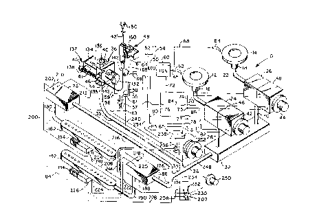
Referring to FIG. 1, a burner control system employing the
to present invention is indicated generally at 10 and has a plurality of gas
burner rings 12,14 such as those of the type employed for the top burners
in a household cooking range. Each of the burners has respectively an
inlet aspirator tube denoted 16,18 into which is inserted a gas supply tube
20,22 respectively, with the supply tubes 20,22 each connected to
15 respectively the outlet of a burner selector valve denoted respectively
. 24,26. Valves 24,26 each have their inlets connected to a manifold outlet
respectively 28,30 of the gas supply manifold 32.
Manifold 32 has its inlet connected to one outlet 38 of a tee which
has its inlet 37 connected to the outlet 34 of an electrically operated line
2o valve indicated generally at 36 by conduit 35 which is indicated in dashed
line in FIG. 1. The opposite outlet 39 of the tee is connected, as will be
hereinafter described, to the inlet of an oven burner manifold. The inlet 40
of line valve 36 is connected to a fuel gas supply such as a natural gas
line or bottled gas.
2s Each of the individual burner valves 24,26 is operated manually
by user, rotation of a selector knob denoted respectively 42,44. Each of
the burner valves 24,26 has attached thereto a cam operated switch
assembly denoted respectively 46,48 which will be described hereinafter in
greater detail.
3o An electronic control unit (ECU) 50 which receives power from
lines 52,54 provides an output control signal to the electric actuator for
line
valve 36.
21~482I
- 6 -
The controller 50 is connected by lead 58 to the electric valve 36
and by lead 55 to one side of a switch 57 which has the opposite side
thereof connected through junction 56 and lead 59 for completing the
circuit to the electric valve actuator. Switch 57 is a user operated switch
remotely located to permit the user to disable the line valve 36 separately
from the functions of the controller 50. The switch 57 may be employed
where desired, as, for example, to provide redundancy of maintaining the
line valve closed for example where there is a risk of small children
tampering with the appliance. The opposite side of the electric actuator for
to valve 36 is connected along lead 58 to junction 61 which is also connected
to junction 63 and to junction 67. Junction 67 is connected along lead 69
to the ECU.
Electronic control unit 50 may include high voltage circuitry 60 for
operating spark ignitors 62,64 which are disposed adjacent respectively
each of the burners, with ignitor 62 connected to the circuitry 60 by lead
65; and, ignitor 64 connected to the ignitor circuitry 60 by lead 68. The
ignitor circuitry 60, which may be of a type well known in the art, receives
input signals from one of the switches in each of the switch assemblies
46,48; and, switch connector lead 72 provides an input from the ignitor
2 o switch in switch assembly 48, whereas lead 76 provides an input to the
ignitor circuitry 60 from the ignitor switch located in cam operated switch
assembly 46. Although the ignitor circuitry is shown as combined with the
ECU, the circuitry 60 may be disposed separately. The opposite side of
the ignitor switch in assembly 98 is connected through lead 74 to junction
2s 75; and, the opposite side of the ignitor switch in assembly 46 is
connected through lead 78 to junction 77 which is connected to junction
75.
Switch assembly 46 also has a separate valve position detecting
switch which has one side connected along lead 80 to the logic control
3 o circuitry of the control unit 50 and the other side connected along lead
82
to junction 81 which is also connected to junction 77 and junction 83,
which is connected along lead 85 to the ECU. A valve position detecting
_ ~ 2154821
switch in switch assembly 48 has one side connected to the controller 50
along lead 84 with the opposite side connected along lead 86 to junction
75.
Referring to FIG. 2, one of the cam actuated switch assemblies
s 46,48 is shown in exploded view it being understood that the internal
construction of the assembly is identical for both of the assemblies 46,48.
Each of the switches 46,48 has a cam drum denoted respectively 88,90
which is received over the rotary valve member shaft denoted respectively
25,27 for each of the burner valves 24,26. It will be understood that
to valves 24,26 may be of a type well known in the art and are operable for
permitting the user to manually control the amount of gas flowing to the
burner. The cam drums 88,90 have each respectively thereon a first
switch actuating cam 92,94 and a second switch actuating cam 96,98.
Cams 92,94 are each disposed for actuating one of the switches indicated
15 generally at 104,106; and 96,98 are each disposed for actuating one of the
switches denoted 100,102. The cam drum 88,90 for each of the
assemblies 46,48 has in internal flat denoted 89,91 which is engaged by a
corresponding flat formed on the shaft 25,27 such that upon rotation of
one of the knobs 42,44 respectively the shaft 25,27 effects movement of
2o the drum 88,90.
It will be understood that the cams 92,94 and 96,98 are located
on the drum 88,90 at a desired rotational position to cause the ignitor
switches 100,102 to close upon initial rotation of the valve shaft 25,27 from
the valve closed or "OFF" position. Upon subsequent rotation of either of
25 the valve shafts 25,27 to an "ON" position, the respective cam lobe 96,98
effects closure of the valve position switch 104,106 respectively to provide
a signal to the electronic control unit 50 that the valve has been
deliberately opened for operation of one of the burners 12,14.
The switch assemblies 46,48 each have the cam drum and
3 o switches 100,102 and 104,106 mounted and retained in a housing
comprising three spacer blocks or sections denoted respectively for each
of the switches by the reference numerals 108,110 and 112,114 and
2~5~82I
_8_
116,118. The spacer blocks are held together by suitable fasteners
passing through the apertures provided in the spacers as denoted by
reference numerals 120,122 and 124,126 and 128,130; and, the fasteners
have been omitted for clarity of illustration. Spacer block 116,118 has a
s plurality of hollow locating bosses 117,119 which engage respectively pins
21,23 and 29,31 on valve 24,26 for orienting the switches with respect to
the rotary position of shaft 25,27.
It will be understood that the rotational position of the cam lobes
92,94 and 96,98 may be altered to provide the desired timing and
to sequence of the closing, including simultaneous closing, of the switches
100,102 and 104,106 with respect to the rotary position of the knobs
42,44.
Referring to FIG. 16, one common known burner valve
arrangement is shown wherein the control knob respectively 42,44 is
15 rotated first to the valve fully open position ("HI") and then to the
ignitor
position for closing one of the ignitor switches 100,102.
Referring to FIG. 17, an alternate arrangement also employed in
present known ranges is shown wherein the knob 42,44 for valve 46,48 is
first rotated to the Ignitor position wherein switch 104,106 closes and then
2o the valve is rotated to the fully open ("HI") position.
Referring to FIGS. 1 and 3-13, the electrically operated line valve
36 is shown as having an electromagnetic operator in the form of solenoid
132 having a pair of connector terminals one of which, denoted by
reference numeral 133, is connected to lead 58 which is connected to
2 s junction 61. The other terminal denoted by reference numeral 135 is
connected via lead 59 to junction 56.
In the illustrated embodiment of FIGS. 3-10, valve 36 has
provided thereon an optional manual override indicated generally at 137
comprising a sliding frame or bracket 134 having a plunger 136 attached
3 o thereto which is slidably secured to the valve body by bracket 139.
Sliding
bracket 134 operable to effect opening and closing of the valve, as will
hereinafter be described, upon sliding movement of the bracket 134
215~82~
- 9 -
between the position indicated in solid outline and the position indicated in
dashed outline in FIGS. 4 and 6.
A cable mounting bracket or tab 138 is formed on bracket 134; and,
tab 138 has received therethrough and anchored thereon an enlarged
s portion illustrated as the ball fitting 140 provided on the end of tension
cable 142. The tension cable 142 extends through a cable jacket 144
having an enlarged end 145 anchored in a second tab 146 provided on
bracket 139 secured to the body of valve 36 by screws 143. The jacket
144 and cable 142 extend upwardly as shown in FIG. 1 into a latching
to device indicated generally at 148 in FIGS. 1 and 11 and an extension
cable 142' extends therefrom to a user actuation knob 150. It will be
understood that when it is desired to manually open the electric valve 36,
during a power outage, the user pulls on knob 150 drawing cable 142'
which overcomes the force of the valve closing or return spring 141, which
15 IS provided between the tab 138 on the moveable bracket 134 and tab 146
on the bracket 139, and moves the bracket 134 and push rod 136 upward
to the position shown in dashed outline which causes the push rod 136 to
effect opening of the valve 36.
Referring to FIGS. 3-10, valve 36 has an armature 162 slidably
2 o mounted within the solenoid 132. The armature 162 is sealed about the
valuing chamber by a cover 164 which serves as the guide for the
armature 162 which is connected to a poppet 166 which seats on a valve
seating surface 168 which seals about an outlet passage 170. The
operating rod 136 extends through a seal 172 provided in the bottom of
25 the valve body and is operative upon upward movement to contact the
undersurface of poppet 166 and open the poppet with respect to the valve
seating surface 168 for manual override. During normal operation, the
electromagnetic force of the solenoid 132 lifts armature 162 and poppet
166 from seating surface 168 for normal service cycling.
3 o Referring to FIGS. 11-13, the latching mechanism indicated
generally at 148 comprises an electromagnetic actuator which in the
present practice comprises a solenoid 152 with pole frame 153 mounted
21~482I
- to -
on a mounting bracket 154 having a flange 156 which is formed to have a
guide tube 155 formed thereon with a latching member 158 slidably
received in the tube 155. The cable jacket 144 has a second enlarged
end portion 147 with a groove 149 formed therein which engages a slotted
s aperture 157 formed in the end of tube 155. The cable 142 has an end
fitting 165 in the form of a "T" bar which engages side slots 159, 161
formed in latching member 158.
The latching member 158 has a slot 163 provided therein which is
engaged by the plate member 171 pinned to the solenoid armature 160
to which is biased by an unknown spring in a direction to engage the slot 163
in the latching member 158 when the cable 142 is pulled by the user.
Upon energization of the solenoid through terminal 162, which is
connected to the electronic control unit 50 via lead 164, and terminal 166
which is connected to junction 67 through lead 168, the armature of the
15 solenoid is pulled in and latching member 158 is released and the sliding
bracket 134 is returned to its valve closing position by spring 141.
Referring to FIG. 1, the fuel line 39 from the Tee is shown as
connected to the inlet of an oven valve manifold or Tee 174 which has one
outlet 176 connected to the inlet of an electrically operated burner valve
2 0 178 whose outlet is connected through conduit 180 to the inlet of an upper
or BROIL burner 182 disposed in the oven 184 indicated by dashed outline
in FIG. 1. The second outlet 186 of manifold or Tee 174 is connected to
the inlet of a second electrically operated burner valve 188 which is
disposed as the lower valve in oven 184. The outlet of valve 188 is
2s connected through conduit 190 to the inlet of the lower or BAKE burner
192.
An electrical resistance type ignitor 194 is disposed adjacent burner
182; and, similarly an electrical resistance type ignitor 196 is disposed
adjacent burner 192.
3 o The electrically operated valves 178,188 are typically of the type
employing a bi-metal valve operator heated by a coil of resistance wire
adjacent the bi-metal operator with the resistance wire connected
2154821
- 11 -
electrically in series with the burner ignitor.
Thus, ignitor 194 has one terminal thereof denoted 198 connected
via lead 200 to one terminal 202 of valve 178. The opposite terminal 204
of ignitor 194 is connected via lead 206 to terminal 207 of a selector
s switch 230. The remaining terminal 210 of valve 178 is connected via lead
212 to junction 63 which is connected also through lead 216 to one
terminal 218 of valve 188. The remaining terminal 220 of valve 188 is
connected via lead 222 to one terminal 224 of ignitor 196, with the
remaining terminal 226 thereof connected via lead 228 to junction 208.
to Junction 208 is connected to both side positions of switch 230 which
has its common terminal 232 connected via lead 234 to one side of oven
thermostatic switch 236 in thermostat 238, with the opposite side of switch
236 connected via lead 240 to junction 56.
The thermostat 238 typically is of the type which includes a fluid
is pressure sensing diaphragm (not shown) which responds to pressure in a
capillary tube 244 connected to a temperature sensing bulb 246 located in
the oven 184. Increases in temperature in the oven create fluid pressure
in the capillary 244 which moves the diaphragm 242 which is connected as
shown in dashed outline in FIG. 14 to the moveable arm of switch 236
2 o which is biased to the normally closed position by a spring (not shown),
the preload of which is varied by a rotary cam (not shown) positioned by
user rotation of knob 248 with which the user selects the temperature
desired in the oven. Upon the oven reaching the desired temperature,
liquid in bulb 246 expands through capillary 244, causing the diaphragm to
2 s open the switch 236 permitting the oven to cool until the liquid in bulb
246
contracts to re-close switch 236 and again provide a signal to the
electronic control unit to relight the burner. The choice of the oven burner
desired for operation is made by the user rotating knob 250 which is
connected as shown by dashed outline in FIG. 1 to effect movement of
3 o the selector switch 230.
Thermostat 238 contains a second switch 252 which is normally
open and has one side connected to junction 83 and the opposite side
21~4~21
- 12 -
connected via lead 254 to the ECU. Switch 252 is closed upon the bulb
246 sensing a preselected oven temperature.
Switch 236 is operated or closed by user rotation of knob 248 from
an open or "OFF" position to a closed position; and, upon closure of switch
s 236, further rotation of knob 248 is operative to select the desired
temperature by changing the length of the internal bias spring (not shown).
Referring to FIGS. 15a and 15b, the circuitry for the system of FIG.
1, wherein the electronic control unit 50 is shown with the top burner valve
position switches 104,106 and the thermostat position switch 252 for the
to oven burners providing inputs respectively through leads 80,84,254 to
diodes D5, D6 and D9 to the ECU 50. It will be understood that on a
range having four top burners, the additional two valve position switches
labelled "OPTIONAL" in FIG. 15a, would provide inputs through diodes
D7, D8.
15 Power line lead 52 is connected to a junction 258 which is
connected to ground through a reverse poled Zener device D2 and also
through capacitor C7. Junction 260 is connected to the supply voltage for
V~ and also to junction 258. The voltage V~ is supplied also to junction
262 which is connected to pin 9 of a D flip-flop U2B. Flip-flop U2B has pin
20 8 grounded and the reset pin 10 connected to a junction 264 which is
connected through capacitor C8 to junction 262.
Referring to FIG. 15b, junction 262 is also connected to junction
266 which is connected to one side of a Triac Q1.
Referring to FIGS. 15a and 15b the output Q at pin 13 of U2B is
25 connected to one input of a NAND device U3B whose output is connected
through resistor R13 to the gate of Triac Q1.
Junction 264 is also connected through a resistor R12 to junction
268 which is grounded and also connected to the SET input, pin 6, of D
flip-flop U2A. U2A has its input pin 5 connected to junction 270 which is
3 o also connected to the CLOCK pin 11 of U2A and also through C1 to
ground. Junction 270 is also connected through resister R1 to junction
272 which is connected through R9 to ground and also connected to one
214821
- 13 -
of the burner valve switch input diodes through junction 273 which is
connected to junction 272. The RESET terminal pin 4 of U2A is connected
to the output of inverter U1C which has its input connected to junction 270.
Junction 270 is also connected to one input of NAND U3A. The CLOCK
s input pin 3 of device U2A is biased by V~ through R7 and is also
connected to junction 272 which is connected through C6 to ground and
also connected to forward poled diode D4 whose opposite pole is
connected to junction 274. Junction 274 is also connected through reverse
pole diode D3 to ground. Junction 274 is also connected through R8 to
to junction 276 which is connected to the output of Triac Q1.
Junction 266 is also series connected through R2 and C3 to junction
276 which is also connected through lead 55 to the one terminal of the line
valve switch 57.
Junction 270 is also connected to the input of inverter amplifier U1C
15 whose output is connected to RESET pin 4 of U2A. Junction 270 is also
connected through one input of NAND U3A whose output is connected to
junction 277 which is connected to the input of inverter amplifier U1B and
also through R4 to junction 278. Junction 278 is connected through R5 to
the remaining input of U3A and also connected through C4 to junction 280
2 o which is connected to the output of U 1 B. Junction 280 is also connected
through C5 to junction 282 which is connected through R6 to ground and
also connected to the input of inverter amplifier U1A whose output is
connected through R11 to the gate of Triac Q2.
One side L1 of the power line is also connected to the input of Triac
25 Q2 and also through R3 and C2 to junction 284. The output of Triac Q2 is
connected through junction 284 and lead 164 to the latching solenoid 152.
The opposite side of the power line 54 is connected through reverse
poled diode D1 and R10 to ground. The values and designations for the
various circuit components are listed in Table I below.
2154821
- 14 -
TABLE 1
R Ohms C ~u FaradsDEVICE TYPE
1 22K 1 0.1 Q 1 TRIAC
2 100,1/2W 2 0.1, 250VQ2 TRIAC
3 100, 1/2W 3 0.1, 250VUlA 4009
4 330 K 4 22 U1B 4009
5 4.3 Meg 5 0.1 U 1 C 4009
6 460 K 6 0.1 U2A 4013
7 7.5 K 7 1500, U2B 4013
25V
8 39K, 1/2 8 O.V U3B 4011
W
9 7.5 K 9 0.1 U3B 4011
10 1.2K, SW D1 1N4004
11 430, 1/2 D2 1N5245, 15V
W
12 100 K D3 1N4004
13 430, 1/2 D4 1N4004
W
In operation, DI, D2, C7 and R10 function as a filter network to provide
a regulated power supply V~ for the circuit.
2o Upon power-up by user closure of either of the switches 104,106 for
the top burners, or selector switch 230 and thermostat switch 252 for the
oven burners, C8 and R12 reset the D flip-flop U2B forcing the Q output of
U2B to a logic zero or "low". When the Q output of U2B is "low" on the input
of NAND gate U3B, the output of U3B goes to a logic one or "high". When
the output of U3B goes "high", this signal applied to the gate of Triac Q1
maintains the Triac Q1 in a non-conductive state and prevents power from
being applied to the line valve switch 57. When the output of U3B goes to a
logic zero or "low", this triggers the Triac Q1 to conduct and apply power to
the line valve switch 57; and if the user closes switch 57, power is applied
to
3 o the solenoid 132 opening line valve 36. To enable D flip-flop U2B (i.e.,
bring
the Q output to a logic "high") requires that either of the burner valve
214821
- 15 -
switches 104,106 be first opened and then closed to provide a rising edge to
the CLOCK input of D flip-flop U2B.
The network comprising R7, R8, D3, D4 and C6 determines the state
of the switch 57. With the Triac Q1 in the non-conductive state and the
switch 57 in the open state, the voltage at the CLOCK input of U2A is at a
steady voltage level of V~ dropped by R7 and filtered by C6. With the switch
57 in the closed state a half wave rectified current goes through R7, R8, D4,
switch 57 and the solenoid 132. D3 acts as a ground clamp so that the
voltage at the CLOCK input does not go below the level of circuit ground.
to This arrangement gives a 60 hertz, 50% duty cycle square wave signal at the
CLOCK input of U2A. The rising edge of this signal will clock in the state of
any of the burner valve switches 104,106 and 100,102 and 252 to the Q
output of U2A and the input to NAND gate U3B. If any of the aforementioned
burner valve switches are in the closed state, then a logic "high" is applied
to
the input of U3B; and, with the Q output of U2B at a logic "high", Triac Q1 is
in the conductive state. With Triac Q1 conducting, there will not be a 60
hertz square wave at U2A CLOCK input. When none of the gas burner valve
switches 104,106 and 252 is in the closed state, the output of inverter U1C
will go "high" resetting the Q output of U2A to a logic "low". This in turn
2o disables the Triac Q1 through the U3B NAND gate cutting off power to the
line valve switch 57.
With any of the gas burner valve switches, 104,106 and 252 in the
closed state, the circuit network comprising U3A, U1B, U1A, R4, R5, R6, C4
and C5 provides a 50 millisecond pulse output at ten second intervals.
Circuit network comprising U3A, U1 B, R4, R5 and C4 performs as a gated
astable oscillator with a time period of ten seconds. The output of U 1 B goes
through the differentiating circuit comprising C5 and R6 to provide a 50
millisecond pulse to the inverter input of U1A whose output drives the gate of
Triac Q2. Thus, each time one of the burner valve switches is closed after
3 o the burner valve has been in the "OFF" or closed state, the solenoid 152
is
energized to release latching mechanism 148.
Referring to FIG. 14, another embodiment of the invention is indicated
215821
- 16 -
generally at 300 for a cooking range having a pair of top burners and a pair
of oven burners arranged in a manner similar to that of the embodiment of
FIG. 1. It will be understood that components which are identical to the
components used in the FIG. 1 embodiment are denoted by the same
reference numeral in FIG. 14. The embodiment of FIG. 14 is similar to the
embodiment of FIG. 1 except that in the FIG. 14 embodiment, the top
burner valves 24,26 are operated by cam actuated switch assemblies
respectively 45", 48" which have only a single cam operated switch therein
for connection to the ignitor circuitry and the ECU 50 as will hereinafter be
to described.
The embodiment 300 of FIG. 14 employs an ignitor circuit 60' which
receives line power at junction 302 from the ECU along leads 303 and 304;
and, junction 302 is also connected to junction 307 and to lead 306 which is
connected to one side of the switch employed in the switch assembly 48". It
will be understood that the internal construction of the switch assembly 48"
is
a single switch corresponding to the construction of the switches illustrated
in
FIG. 2. The other side of the switch in assembly 48" is connected via lead
308 to junction 310 which is connected via lead 312 to the ignitor circuitry
and through lead 314 to one of the EUC inputs such as diode D5 in FIG.
15a.
Junction 307 is also connected via lead 316 to provide power to one
side of a switch located within the burner valve switch assembly 46" which
may be of construction identical to one of the switches illustrated in FIG. 2.
The other side of the burner valve switch located within assembly 46" is
2s connected via lead 318 to junction 320 which is connected via lead 322 to
one of the inputs such as diode D6 of the ECU 50. Junction 320 is also
connected via lead 324 to the ignitor circuit.
The ignitor circuitry 60' is connected along lead 328 via junction 58 to
terminal 133 of the line valve solenoid 132. Junction 56 is connected to one
3 o side of line valve switch 57 via junction 325 and also along lead 330 to
the
ignitor circuitry.
It will be understood that the ignitor circuitry 60' is of the type which
CA 02154821 1999-11-16
- 17 -
responds to the presence of flame on either of the spark electrodes 64,62 to
provide a signal to discontinue the sparking. Such techniques are well-
known in the art as for example by flame rectification or change in resistance
due to the presence of flame.
In operation, the user closes switch 57 and rotates one of the burner
valve control knobs 248,42,44 to effect closing of one of the switches
252,46",48", thereby providing a signal to the ECU along one of the leads
254,322,314 and to the ignitor circuitry 60' along leads 324,312. The ignitor
circuitry is operative to begin sparking on one of the electrodes 64,62 and to
to complete a circuit to permit current to flow along lead 328 to solenoid
terminal 133, through the solenoid 132 and through switch 57; and, only upon
the ECU sensing the appropriate sequence of events as described
hereinabove with respect to the embodiment of FIG. 1, e.g., that the switch
57 has been closed (to provide an arming signal) before one of the burner
valve
switches, current is allowed to flow to the Neutral to complete a circuit.
In the event of the Loss of flame at one of the burners 12,14, the
igniter circuitry 60' is operative to begin sparking again automatically in a
manner well known in the art.
The present invention thus provides a unique control system for
2 o gaseous fuel burners wherein the user must first close a line switch
series
connected with an electrical line valve operator and then open one of the
burner valves such that the switch senses the valve position and signals an
electronic control unit which then completes the circuit to the line valve
operator to effect opening of the line valve and fuel flow to the burner. The
control system of the present invention may include a manually actuated
override for enabling the line valve to opened during periods of power
outage. The control system of the present invention may be employed for a
range having a plurality of top burners and oven burners and may be
employed either with or without flame sensing techniques for the ignitors
3 o utilized with the top burners.
Although the invention has hereinabove been described with respect to
the illustrated embodiments, it will be understood that the invention is
21~482I
- 18 -
capable of modification and variation and is limited only by the following
claims.