Note: Descriptions are shown in the official language in which they were submitted.
215 ~ 9'~ 1
- 1 -
PATENT
ATTORNEY DOCKET NO: 05242/061CA1
SYSTEM AND APPARATUS FOR CONVERSION OF THERMAL
ENERGY INTO MECHANICAL AND ELECTRICAL POWER
Backaround of the Invention
The invention relates generally to methods and
apparatus for transforming energy from a heat source into
usable form using a working fluid that is expanded and
regenerated. The invention further relates to methods
and apparatus for improving the heat utilization
efficiency of a thermodynamic cycle.
In the Rankine cycle, a working fluid such as
water, ammonia, or a freon is evaporated in an evaporator
utilizing an available heat source. The evaporated
gaseous working fluid is expanded across a turbine to
transform its energy into usable form. The spent gaseous
working fluid is then condensed in a condenser using an
available cooling medium. The pressure of the condensed
working medium is increased by pumping, followed by
evaporation and so on to continue the cycle.
The Exergy cycle, described in U.S. Pat. No.
4,346,561, utilizes a binary or multi-component working
fluid. This cycle operates generally on the principle
that a binary working fluid is pumped as a liquid to a
high working pressure and is heated to partially vaporize
the working fluid. The fluid is then flashed to separate
high and low boiling working fluids. The low boiling
component is expanded through a turbine, to drive the
turbine, while the high boiling component has heat
recovered for use in heating the binary working fluid
prior to evaporation. The high boiling component is then
mixed with the spent low boiling working fluid to absorb
the spent working fluid in a condenser in the presence of
a cooling medium.
215471
- 2 -
In applicant's further invention, referred to as
the Basic Kalina cycle, the subject of U.S. Pat. No.
4,489,563, relatively lower temperature available heat is
utilized to effect partial distillation of at least a
portion of a multi-component fluid stream at an
intermediate pressure to generate working fluid fractions
of differing compositions. The fractions are used to
produce at least one main rich solution which is
relatively enriched with respect to the lower boiling
component, and to produce one lean solution which is
relatively impoverished with respect to the lower boiling
component. The pressure of the main rich solution is
increased; thereafter, it is evaporated to produce a
charged gaseous main working fluid. The main working
fluid is expanded to a low pressure level to convert
energy to usable form. The spent low pressure level
working fluid is condensed in a main absorption stage by
dissolving with cooling in the lean solution to
regenerate an initial working fluid for reuse.
In accordance with another invention of the
applicant, the subject of U.S. Pat. No. 4,604,867, a
fluid may be diverted to a reheater after initial
expansion in the turbine to increase the temperature
available for superheating. After return to the turbine,
and additional expansion, the fluid is withdrawn from the
turbine and cooled in an intercooler. Afterwards, the
fluid is returned to the turbine for additional
expansion. The cooling of the turbine gas may provide
additional heat for evaporation. Intercooling provides
compensation for the heat used in reheating and may
provide recuperation of heat available which would
otherwise remain unused following final turbine
expansion_
It would be desirable to further increase the
efficiency of the aforementioned thermodynamic cycles.
215471
- 3 -
Summary of the Invention
It is one feature of the present invention to
provide a significant improvement in the efficiency of a
thermodynamic cycle by a process that includes the steps
of
expanding a gaseous working fluid to transform its
energy into useable form and generating a spent stream;
condensing the spent stream producing a condensed
stream;
generating from the condensed stream a first
stream having a higher percentage of a low boiling
component than is included in the condensed stream, a
second stream having a lower percentage of a low boiling
component than is included in the condensed stream, and a
third stream having the same percentage of a low boiling
component as is included in the condensed stream;
subjecting said first, second, and third streams
to multiple distillation operations to generate a liquid
working fluid; and
evaporating the liquid working fluid to generate
the gaseous working fluid.
In preferred embodiments, the multiple
distillation operations yield generate a vapor stream
which is condensed to generate the liquid working fluid,
and a liquid stream which is mixed with the spent working
fluid. It is preferably to perform the distillation in
at least two stages (and more preferably in at least
three stages).
In one particularly preferred embodiment, the
first, second, and third streams are generated as
follows. The condensed stream is divided into first and
second substreams. The pressure of the first substream
is increased to form a first pressurized substream.
Similarly, the pressure of the second substream is
increased to form a second pressurized substream; the
zlS4~'~I
- 4 -
pressure of the second pressurized substream is greater
than the pressure of the first pressurized substream.
The first pressurized substream is partially evaporated
to form a partially evaporated stream, which is then
separated into a vapor stream and a liquid stream. The
pressure of the liquid stream is increased to the same
level as the second pressurized substream to form a
stream having a lower percentage of a low boiling
component than is included in the condensed stream (i.e.,
the second stream). The vapor stream is mixed with a
portion of the first pressurized substream to form a
composite stream having the same composition as the
condensed stream, which is then condensed to form a
condensed composite stream. The pressure of the
condensed composite stream is increased to a level equal
to that of the second pressurized substream to form a
pressurized condensed composite stream, which is then
heated (along with the second pressurized substream) to
form, respectively, a stream having the same composition
as the condensed stream (i.e., the third stream) and a
stream having a higher percentage of a low boiling
component than is included in the condensed stream (i.e.,
the first stream).
Other features and advantages of the invention
will be apparent from the following description of the
preferred embodiments thereof, and from the claims.
Brief Description of the Drawings
FIG. 1 is a schematic representation of a system
for carrying out the method and apparatus of the present
invention.
FIG. 2 is a schematic representation of one
embodiment of a distillation condensation subsystem that
may be used in the present invention.
FIG. 3 is an axonometric representation of the
distillation condensation subsystem shown in FIG. 2.
z~54~ r1
- 5 -
FIG. 4 is a schematic representation of a second
embodiment of a distillation condensation subsystem that
may be used in the present invention.
Description of the Preferred Embodiments
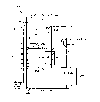
The schematic shown in FIG. 1 shows an embodiment
of preferred apparatus that may be used in the method and
system of the present invention. Specifically, FIG. 1
shows a system 200 that includes a boiler 201, turbines
202, 203, and 204, intercooler 205, distillation
condensation subsystem (DCSS) 206, pump 207, stream
separator 208, stream mixer 209, and admission valve 210.
Various types of heat sources may be used to drive
the cycle of this invention, including for example, gas
turbine exhaust gases. In this regard, the system of the
present invention may be used as a bottoming cycle in
combined cycle systems.
The working stream flowing through system 200 is a
multi-component working stream that comprises a lower
boiling point fluid (the low boiling component) and a
higher boiling point fluid (the high boiling component).
Preferred working streams include ammonia-water mixtures,
mixtures of two or more hydrocarbons, two or more freons,
mixtures of hydrocarbons and freons, or the like. In
general, the working stream may be a mixture of any
number of compounds with favorable thermodynamic
characteristics and solubility. In a particularly
preferred embodiment, a mixture of water and ammonia is
used.
As shown in FIG. 1, a completely condensed working
fluid having parameters as at 22 passes through the
preheater portion of heat recovery boiler 201 where it is
heated to a temperature a few degrees below its boiling
temperature and obtains parameters as at 44. This
preheating is provided by the cooling of all streams of a
heat source indicated in dashed lines through boiler 201.
2154~'~~
- 6 -
The working fluid which exits the preheater is divided by
stream separator 208 into two separate streams having
parameters as at 45 and 46, respectively.
A first stream having parameters as at 46 enters
the evaporator portion of boiler 201 while the second
stream (having parameters as at 45) enters intercooler
205. The first stream is heated in the evaporator by the
countercurrent heating fluid flow described above,
obtaining parameters as at 48. The second fluid stream
passing through the intercooler 205 is heated by
countercurrent fluid flow, thereby obtaining parameters
as at 47. Both the first and second streams are
completely evaporated and initially superheated. Each of
the streams has approximately the same pressure and
temperature but the streams may have different flow
rates. The fluid streams from the evaporator and
intercooler 205 are then recombined by stream mixer 209,
thereby obtaining parameters as at 49.
The combined stream of working fluid is sent into
the superheater portion of boiler 201 where it is finally
superheated by heat exchange with the heat source stream
described above and obtains parameters as at 30. Thus,
the heat source stream extending from point 25 to point
26 passes first through the superheater, then through the
evaporator, and finally through the preheater. The
enthalpy-temperature characteristics of the illustrated
heating fluid stream is linear.
From the superheater portion of boiler 201, the
total stream of working fluid (having parameters as at
30) passes through admission valve 210, thereby obtaining
parameters as at 31, and enters a first turbine 202 which
may include a number of stages. In turbine 202, the
working fluid expands to a first intermediate pressure,
thereby converting thermal energy into mechanical energy,
and obtains parameters as at 40.
z~s~~~~
_ 7 _
The whole working fluid stream from turbine 202
(having parameters as at 40) is reheated by passing again
through boiler 201 using heat generated by the
countercurrent fluid flow through boiler 201 described
above and obtains parameters as at 41. Having been
reheated to a high temperature, the stream of working
fluid leaves boiler 201 and travels to a second turbine
203 which may include a number of stages.
The working fluid in turbine 203 is expanded from
the first intermediate pressure to a second intermediate
pressure, thus generating power. The total stream of
working fluid (having parameters as at 42) is then sent
to intercooler 205 where it is cooled, providing the heat
necessary for the evaporation of the second working fluid
stream. Intercooler 205 may be a simple heat exchanger.
The working fluid stream (having parameters as at 43)
then exits intercooler 205 and travels to a third turbine
204 (which may also include multiple stages).
In turbine 204, the working fluid expands to the
final spent fluid pressure level, thus producing
additional power. From turbine 204 the working fluid
stream (having parameters as at 38) is passed through
distillation condensation subsystem (DCSS) 206 where it
is condensed (thereby obtaining parameters as at 29),
pumped to a higher pressure by pump 207 (thereby
obtaining parameters as at 32), and sent to boiler 201 to
continue the cycle.
The distillation condensation subsystem (DCSS) 206
will now be described.
Referring to FIGS. 2 and 3, the working fluid
exiting low pressure turbine 204 (in the form of a
saturated vapor having parameters as at point 38), passes
through heat exchanger 1 where it is partially condensed
and cooled, yielding a stream having parameters as at
point 16. Thereafter, this stream is mixed with a second
2I549'~~
_$_
stream of liquid having parameters as at point 19 and in
thermodynamic equilibrium with the stream having
parameters as at point 16. The stream having parameters
as at point 19 contains less low boiling component (e. g.,
ammonia) than the stream having parameters as at point 16
and is thus said to be "lean" relative to the stream
having parameters as at point 16.
Mixing the two streams yields a third stream
having parameters as at 17. Because the stream having
parameters as at point 19 is leaner than the stream
having parameters as at point 16, the composition of this
third stream produced as a result of mixing the first and
second streams is also lean relative to the first stream
(i.e., the stream having parameters as at point 16).
The third stream with parameters as at point 17
passes through heat exchanger 5 where it further cooled
and condensed, obtaining parameters as at point 87.
Thereafter, the third stream passes to heat exchanger 7
where it is further cooled and condensed, obtaining
parameters as at point 86 (where it is in the form of a
mixture of vapor and liquid). A small portion of the
liquid (having parameters as at point 83) can be
separated and extracted from the third stream at point 86
and as a result the third stream obtains parameters as at
point 84. Thereafter, the third stream (having
parameters as at point 84) passes through heat exchanger
11 where it is further cooled and condensed, obtaining
parameters as at point 15.
Next, the third stream (having parameters as at
point 15) is mixed with another liquid stream having
parameters as at point 132 to form yet another stream
having parameters as at point 18. The composition of the
stream at point 18 is such that it allows this stream to
be fully condensed under the existing pressure and
temperature conditions. The stream having parameters as
~154~'l~
_ g _
at point 18 then passes through heat exchanger 14 where
it is fully condensed by a stream of cooling water having
parameters as at points 23-59 to yield a stream having
parameters as at point 1.
Thereafter, the stream having parameters as at
poin'~ 1 is divided into two substreams which are
correspondingly pumped by pump P1 to an intermediate
pressure and by pump P2 to a high pressure. As a result,
after pump P1 one of the substreams obtains parameters as
at point 2 and after pump P2 the other substream obtains
pa_.r_ameters as at point 20.
A portion of the stream having parameters as at
point 2 is then separated to form another stream having
parameters as at point 8. The rest of the stream is
divided into two additional substreams which pass,
respectively, through heat exchanger 9 and heat exchanger
11, where each is preheated to boiling temperature
(corresponding to points 147 and 148, respectively) and
then partially boiled, obtaining parameters as at points
145 and 146, respectively. Thereafter, these two
substream~ are combined to create another stream having
parameters as at point 105, which is then sent into
gravity separator S1.
In gravity separator S1, the stream having
parameters as at point 105 is separated into a stream of
saturated vapor having parameters as at point 106 and a
stream of saturated liquid having parameters as at point
107. The stream consisting of saturated vapor with
parameters as at point 106 may, in turn, be subdivided
into a first stream with parameters as at point 133
(minor portion) and a second stream with parameters as at
point 134 (major portion).
The stream having parameters as at point 134 is
then mixed with the stream of liquid having parameters as
at point 8 (described above), creating a stream (a so-
21 54971
-lo-
called "intermediate solution") having parameters as at
point 73. The composition at point 73 is such that the
stream can be fully condensed by cooling water of
available temperature at its intermediate pressure. The
stream having parameters as at point 73 then passes
through heat exchanger 13 where it is cooled by water
(stream 23-99) and fully condensed, thereby obtaining
parameters as at point 74.
Thereafter, the stream having parameters as at
point 74 is pumped to a high pressure by pump P3, thereby
obtaining parameters as at point 72. As a result, two
streams having identical high pressures but different
compositions with parameters as at points 20 and 72,
respectively, are created. These two streams pass
through heat exchanger 8 where they are heated, obtaining
parameters as at points 71 and 39, respectively.
The stream having parameters as at point 39 has a
rich composition relative to the stream having parameters
as at point 71. A portion of the stream having
parameters as at point 107 (described above) is also
pumped by pump P4 to a high pressure and thereby obtains
parameters as at point 129.
As a result, three streams having parameters,
respectively, as at 129, 39, and 71, have been created.
These three streams have three different compositions but
identical pressures. The "lean" stream has parameters as
at point 129, the "intermediate" stream has parameters as
at point 71, and the "rich" stream has parameters as at
point 39.
A small portion of the lean stream having
parameters as at point 129 is separated to form a stream
having parameters as at point 113; the remaining portion
of the stream then obtains parameters as at point 127. A
small portion of the intermediate stream having
parameters as at point 71 is also separated to form a
~1549'~1
- 11 -
stream having parameters as at point 70; the remaining
portion of the stream then obtains parameters as at point
111. The rich stream having parameters as at point 39 is
divided into two substreams having parameters,
respectively, as at points 110 and 33.
The compositions of the streams having parameters
as at point 129, 111, and 110, respectively may be
altered. Specifically, the composition of the stream
having parameters as at point 129 can be made leaner in
the following way. Liquid having parameters as at point
83 (described above) is pumped by pump P5 to a pressure
equal to the pressure of the stream having parameters as
at point 129. After pumping, the liquid having
parameters as at point 83 obtains parameters as at point
82. Because the composition of a stream with parameters
as at point 82 is leaner than that of the stream having
parameters as at point 127, mixing these two streams will
result in a composite stream having leaner composition
than that of the stream at point 127.
On the other hand, a portion of a stream having
parameters as at point 70 which is extracted for
intermediate composition stream, this portion having
parameters as at point 9, may be added to the stream
having parameters as at point 127. Because the stream
having parameters as at point 9 has a richer composition
than the stream having parameters as at point 127, the
composite stream formed by mixing the two has a richer
composition compared to the stream having parameters as
at point 127.
Thus, the stream having parameters as at point 127
can be made leaner by adding a stream having parameters
as at point 82, or richer by adding a stream having
parameters as at point 9. Only one of these streams is
added any time. As a result, a stream having parameters
as at point 128 is created.
215~97~
- 12 -
A stream having parameters as at point 113
(extracted from the stream having parameters as at point
129) may be added to the stream having parameters as at
point 111 to create a stream having a slightly leaner
composition (relative to the stream having parameters at
point 111) and parameters as at point 112. A stream
having parameters as at point 110 can also be may be made
leaner by addition of a portion of the stream having
parameters as at point 70, this portion having parameters
as at point 123. A new stream with a slightly leaner
composition (relative to the stream having parameters as
at point 110) having parameters as at point 80 is thus
created.
As a result of such remixing and altering the
composition of the streams, four streams having four
different compositions (i.e., having parameters as at
points 33, 112, 128 and 80, respectively) are created.
The stream having parameters as at point 33 (which
is in the form of a saturated liquid) passes through heat
exchanger 7, thereby obtaining parameters as at point 35.
It is then sent into gravity separator S2 where it is
separated into two streams. One of the streams is in the
form of a saturated vapor having parameters as at point
36, and the other stream is in the form of a saturated
liquid having parameters as at point 37.
As can be seen from Figs. 2 and 3, each stream
being vaporized enters the heat exchanger from the bottom
and is removed in a partially vaporized state from the
top of the heat exchanger. After separation of vapor and
liquid, the saturated liquid produced in such a separator
is subject to further vaporization. Because such a
liquid has to enter in the next heat exchanger from the
bottom, excessive pressure in the pipeline leading from
bottom to the top of the heat exchanger could build up.
To avoid such pressure build-up, the saturated liquid
2i54~71
- 13 -
leaving the gravity separator (e. g., the liquid at point
37) is subcooled to form a liquid having parameters as at
point 137.
The stream with parameters as at point 112 passes
through heat exchanger 6 where it is heated and obtains
parameters as at point 78. Thereafter, this stream is
directed down to the bottom of the heat exchanger and,
because of added pressure created by hydraulic height,
obtains increased pressure and has parameters as at point
79. The stream having parameters as at point 78 has a
richer composition than saturated liquid would have at
the temperature existing at point 79. However, because
this stream also has a slightly higher pressure, boiling
does not occur.
The stream having parameters as at point 79 is
mixed with the stream having parameters as at point 137
(as described above) to form a composite stream having
parameters as at point 7. During such mixing, the
pressure of the resulting composite stream having
parameters as at point 7 is reduced by means of
throttling; as a result the stream at point 7 emerges in
the state of a saturated liquid.
The stream with the leanest composition having
parameters as at point 128 also passes through heat
exchanger 6 where it is heated and obtains parameters as
at point 138. Thereafter, this stream is returned to the
bottom of the heat exchanger, causing its pressure to
increase as a result of the height of the hydraulic
column. The resulting stream obtains parameters as at
point 126.
The stream with parameters as at point 7 is
divided int two substreams which pass, respectively,
through heat exchanger 5 and heat exchanger 4. In those
two heat exchangers, these substreams are vaporized and
obtain parameters, respectively, as at points 144 and
2I~~9~1
- 14 -
143. Thereafter, those two substreams are recombined to
form a stream having parameters as at point 75, which is
then sent into gravity separator S3. In separator S3 the
stream having parameters as at point 75 is separated into
vapor having parameters as at point 75 and saturated
liquid having parameters as at point 77.
The stream with parameters as at point 126 (the
lean stream) is also sent through heat exchanger 4 where
it is heated and obtains parameters as at point 125.
Thereafter, the streams having parameters as at points 77
and 125 are sent to the bottom of the heat exchangers and
their pressure increases. As a result, these streams
obtain parameters, respectively, as at points 136 and
124. Again, the stream with parameters as at point 124
has a composition which is richer than the composition of
saturated liquid at the same temperature, and the stream
having parameters as at point 136 has a composition which
is leaner than the composition of saturated liquid at the
same temperature. These two streams are then mixed to
create a composite stream having parameters as at point 4
which is in the form of a saturated liquid.
The stream having parameters as at point 4 is
split int three substreams which pass, respectively,
through heat exchangers 1, 2, and 3 where these
substreams are partially vaporized, obtaining parameters,
respectively, as at points 142, 140 and 141. The three
streams are then recombined to form a stream having
parameters as at point 5.
The stream having parameters as at point 5 is sent
into gravity separator S4 where it is separated into
vapor having parameters as at point 5 and saturated
liquid having parameters as at point 10. The liquid
having parameters as at point to passes through heat
exchanger 3 where it is cooled, providing heat for
vaporization (as described above) and obtaining
zm~9~1
- 15 -
parameters as at point 12. The stream having parameters
as at point 12 is then throttled to lower its pressure,
thereby obtaining parameters as at point 19. The stream
having parameters as at point 19 is then combined with
the low pressure stream having parameters as at point 16
(described above) to create a stream having parameters as
at point 17.
Vapor having parameters as at point 6 passes
through heat exchanger 2 where it is partially condensed,
providing heat for vaporization as described above and
obtaining parameters as at point 116. The stream having
parameters as at point 116 is then combined with the
stream of vapor from gravity separator S3 having
parameters as at point 76 (described above), producing a
stream having parameters as at point 117. The stream
having parameters as at point 117 then passes through
heat exchanger 4 where it is further condensed and
cooled, thereby providing heat for vaporization and
heating as described above and obtaining parameters as at
point 118. Thereafter, the stream having parameters as
at point 118 is mixed with the vapor having parameters as
at point 36 which leaves gravity separator S2 (described
above) to create a stream having parameters as at point
119.
The stream having parameters as at point 119 then
passes through heat exchanger 6 where it is further
cooled and condensed, providing heat for heating the two
streams of liquid passing through heat exchanger 6 (as
described above) and obtaining parameters as at point
120. Thereafter, the stream having parameters as at
point 120 is mixed with the stream of rich liquid having
parameters as at point 80 (described above); the
composition of the stream having parameters as at point
80 has been altered in such a way that this stream is in
thermodynamic equilibrium with the stream having
Z1549'~I
- 16 -
parameters as at point 120. The resulting composite
stream has parameters as at point 122. The composition
at point 122 is equal to the composition of vapor which
has entered Distillation Condensation Subsystem 206
(i.e., the composition of the stream at point 38).
However, the pressure of the stream is higher than the
stream with parameters as at point 38, which allows it to
be condensed by cooling water at available temperature.
The stream having parameters as at point 122 is
divided into two substreams which are sent, respectively,
into heat exchangers 8 and 9. In those two heat
exchangers, these substreams are further cooled and
condensed, thereby providing heat for vaporization in
heat exchanger 9 and for heating of liquids in heat
exchanger 8 (as described above), and obtaining
parameters as at points 115 and 114, respectively.
Thereafter, the two substreams are recombined to form a
stream having parameters as at point 13, which is then
sent into heat exchanger 12 where it is finally fully
condensed by a stream of cooling water (23-58), thereby
obtaining parameters as at point 14.
The stream having parameters as at point 14 is
pumped by a booster pump P6 to elevated pressure and then
sent into heat exchanger 10 where it is heated, thereby
obtaining parameters as at point 29. It is then sent
into boiler 201 as described above with reference to FIG.
1.
The liquid leaving left gravity separator S1
(described above) is sent into heat exchanger 10 and,
upon being cooled, obtains parameters as at point 131,
thereby providing heat necessary for heating water stream
21-29. In the event that the heat available from cooling
this liquid is not sufficient to provide necessary
heating, a small portion of the vapor from gravity
separator S1 having parameters as at point 133 may be
2159?1
- 17 -
added to the liquid which is being cooled in heat
exchanger 10. Condensation of this vapor provides the
necessary heat balance in heat exchanger 10.
The stream having parameters as at point 131 is
throttled to reduce its pressure, thereby obtaining
parameters as at point 132. The stream having parameters
as at point 132 is then mixed with the stream having
parameters as at point 15, creating a stream having
parameters as at point 18 (described above) and providing
for full condensation of low pressure stream which has
entered Distillation Condensation Subsystem 206 after
exiting the low pressure turbine.
The cycle is closed.
Suggested parameters for the points corresponding
to the points set forth in system 200 shown in FIG. 1 are
presented in Table I for a system having a water-ammonia
working fluid. Suggested parameters for the points
corresponding to the points set forth in DCSS 206 shown
in FIGS. 2 and 3 are presented in Table I for a system
having a water-ammonia working fluid. A summary of the
performance of the system shown in FIGS. 1-3, using the
parameters shown in Tables 1 and 2, is included in Table
3.
The system of the present invention should provide
for an increased thermal efficiency when compared to the
system described in U.S. Pat. No. 4,604,867. As shown in
Table 3, a combined cycle utilizing the proposed
bottoming cycle system has a net output of 252,733.4 kWe.
For comparison, the combined cycle system in accordance
with U.S. Pat. No. 4,604,867 with the same gas turbine (a
GE 7FA gas turbine) has a net output of 249,425 kWe, and
the combined cycle with the same gas turbine using a
conventional triple pressure Rankine bottoming cycle has
a net output of 240,432 kWe. As follows from this data,
the proposed system outperforms the most advanced
215~9'~~
-18-
combined cycle with a Rankine bottoming cycle by 12,301
kWe and outperforms the combined cycle system in
accordance with U.S. Pat. No. 4,604,867 by 3,307.5 kWe.
While the present invention has been described
with respect to a preferred embodiment, those skilled in
the art will appreciate a number of variations and
modifications of that embodiment. For example, it is
also possible to perform the distillation operation in
two stages (as opposed to three stages, as shown in FIGS.
2 and 3) using the same principles. Such a simplified
design of the proposed system is presented in Figure 4.
Although it has a somewhat lower performance (752,602 kWe
vs. 752,733.4 kWe), it contains fewer heat exchangers in
the Distillation Condensation Subsystem (12 vs. 14).
The number of distillation steps can also be
greater than three.
2154971
Tablel
DISTILLATION-CONDENSATION SUBSYSTEM POINTS
# P psiA X T °F H BTU~b C~30 Flow tYhr Phase
1 44.90 .5568 63.00 -69.47 3.0951 2,414,827 SatLiquid
2 71.49 .5568 63.05 -69.35 2.4736 1,929,890 Liq 25
3 61.49 .5568 79.65 -51.59 1.5737 1,227,803 SatLiquid
4 102.23 .4814 127.87 -3.62 1.2477 973,428 SatLiquid
99.23 .4814 178.78 212.96 1.2477 973,428 Wet .7438
6 99.23 .9471 178.78 649.99 .3196 249,382 SatVapor
7 101.83 .5433 112.08 -17.47 1.1246 877,430 SatLiquid
8 71.49 .5568 63.05 -69.35 .8999 702,087 Liq 25
9 110.39 .5568 93.19 -36.86 .0679 53,014 Liq 21
99.23 .3210 178.78 62.43 .9280 724,046 SatLiquid
11 105.87 .6365 88.03 -33.03 .0000 0 Liq 8
12 99.23 .3210 131.87 12.79 .9280 724,046 Liq 47
13 97.68 .8500 78.50 252.60 1.0000 780,206 Wet .5256
14 97.38 .8500 63.00 -11.76 1.0000 780,206 SatLiquid
45.20 .5954 81.13 86.94 1.9280 1,504,253 Wet .777
16 46.35 .8500 132.01 511.68 1.0000 780,206 Wet .1797
17 46.35 .5954 132.01 271.55 1.9280 1,504,253 Wet .5745
18 45.20 .5568 79.17 29.65 3.0951 2,414,827 Wet .8648
19 46.35 .3210 132.01 12.79 .9280 724,046 SatLiquid
130.39 .5568 63.17 -69.10 .6215 484,936 Liq 62
21 216.54 .8500 63.33 -11.15 1.0000 780,206 Liq 50
23 Water 57.00 25.00 44.0603 34,376,098
58 Water 70.74 38.74 19.2413 15,012,208
59 Water 75.02 43.02 17.0232 13,281,579
99 Water 72.41 40.41 7.7958 6,082,312
24 Water 72.69 40.69 44.0603 34,376,098
29 196.54 .8500 89.19 17.36 1.0000 780,206 Liq 17
33 101.43 .6365 93.19 -27.44 .8963 699,325 SatLiquid
35 98.43 .6365 112.08 116.07 .8963 699,325 Wet .7783
36 98.43 .9952 112.08 587.00 .1987 155,062 SatVapor
37 98.43 .5343 112.08 -18.10 .6976 544,263 SatLiquid
38 46.75 .8500 184.58 707.60 .9904 772,706 SatVapor
39 102.43 .6365 93.19 -27.41 1.0996 857,879 Liq 1
70 0.00 .5568 0.00 0.00 .2019 157,548
71 110.39 .5568 93.19 -36.86 .6215 484,936 Liq 21
72 122.43 .6365 63.14 -59.97 1.0996 857,879 Liq 42
73 59.99 .6365 76.58 48.98 1.0996 857,879 Wet .835
74 59.69 .6365 63.00 -60.25 1.0996 857,879 SatLiquid
75 98.83 .5433 127.87 77.52 1.1246 877,430 Wet .865
76 98.83 .9898 127.87 599.11 .1518 118,454 SatVapor
77 98.83 .4736 127.87 -3.88 .9728 758,976 SatLiquid
-
78 108.39 .5581 112.08 -16.23 .4270 333,167 Liq 1
79 116.43 .5581 112.08 -16.22 .4270 333,167 Liq 5
80 98.03 .6041 93.95 -31.25 .3298 257,309 Liq 3
81 142.43 .6365 93.19 -27.41 .0074 5,779 Liq 1
82 137.48 .4235 97.35 -35.94 .0000 0 Liq 67
83 45.55 .4235 97.19 -36.33 .0000 0 SatLiquid
- 19 -
215 4 ~'1 ~.
Table 1(continued)
# P psiA X T F H BTU/b C~C30 Fbw 64u Phase
84 45.55 .5954 97.19 152.92 1.9280 1,504,253 Wet .6974
85 45.35 .5954 83.65 97.81 1.9280 1,504,253 Wet .7634
86 45.55 .5954 97.19 152.92 1.9280 1,504,253 Wet .6974
87 45.95 .5954 116.08 219.59 1.9280 1,504,253 Wet .626
89 105.87 .5568 88.03 -42.45 .0000 0 Liq 23
105 59.99 .5568 93.19 38.45 1.5737 1,227,803 Wet .8731
106 59.99 .9956 93.19 582.24 .1997 155,798 SatVapor
107 59.99 .4930 93.19 -40.59 1.3740 1,072,006 SatLiquid
108 59.99 .9956 93.19 582.24 .1997 155,792 SatVapor
109 59.99 .9956 93.19 582.24 .1997 155,792 SatVapo~
110 98.03 .6365 91.39 -27.41 .1958 152,775 Wet .9963
111 110.39 .5568 93.19 -36.86 .4196 327,388 Liq 21
112 128.39 .5581 93.19 -36.71 .4270 333,167 Liq 30
113 137.48 .4930 93.33 -40.25 .0000 0 Liq 51
114 97.68 .8500 75.32 224.52 .4419 344,788 Wet .5731
115 97.68 .8500 81.58 274.84 .5581 435,418 Wet .489
116 98.83 .9471 135.01 561.70 .3196 249,382 Wet .0724
117 98.83 .9608 132.98 573.75 .4715 367,835 Wet .0494
118 98.43 .9608 117.33 549.65 .4715 367,835 Wet .0683
119 98.43 .9710 116.08 560.72 .6702 522,898 Wet .0484
120 98.03 .9710 100.27 539.33 .6702 522,898 Wet .065
121 97.83 .8500 83.65 287.37 .5581 435,418 Wet .4688
122 98.03 .8500 97.60 350.88 1.0000 780,206 Wet .3738
123 98.03 .5568 93.21 -36.86 .1340 104,534 Liq 14
124 116.83 .5087 127.87 -2.22 .2749 214,452 Liq 1
125 115.48 .5087 127.87 -2.22 .2749 214,452 Liq 1
126 135.48 .5087 112.08 -19.37 .2749 214,452 Liq 27
127 137.48 .4930 93.33 -40.25 .2069 161,438 Liq 51
128 137.48 .5087 93.19 -39.72 .2749 214,452 Liq 47
129 137.48 .4930 93.33 -40.25 .2069 161,438 Liq 51
130 59.99 .4930 93.19 -40.58 1.1671 910,574 SatLiquid
131 59.69 .4930 70.28 -65.01 1.1671 910,574 Liq 23
132 45.20 .4930 70.31 -65.01 1.1671 910,574 Liq 8
133 59.99 .9956 93.19 582.24 .0000 6 SatVapo~
134 59.99 .9956 93.19 582.24 .1997 155,792 SatVapor
135 59.99 .4930 93.19 -40.59 1.1671 910,568 SatLiquid
136 116.83 .4736 127.87 -3.81 .9728 758,976 Liq 11
137 116.43 .5343 112.08 -18.04 .6976 544,263 Liq 11
138 117.48 .5087 112.08 -19.40 .2749 214,452 Liq 17
139 98.01 .8500 92.03 328.97 .4406 343,741 Wet .405
140 99.23 .4814 174.78 198.56 .1396 108,902 Wet .7587
141 99.23 .4814 174.78 198.56 .2279 177,772 Wet .7587
142 99.23 .4814 180.45 218.96 .8802 686,754 Wet .7377
-
143 98.83 .5433 127.87 77.52 .0701 54,700 Wet .865
144 98.83 .5433 127.87 77.52 1.0545 822,730 Wet .865
145 59.99 .5568 93.19 38.45 .3937 307,159 Wet .8731
146 -59.99 .5568 93.19 38.45 1.1800 920,644 Wet .8731
147 61.49 .5568 79.65 -51.59 .3937 307,159 SatLiquid
148 61.49 .5568 79.65 -51.59 1.1800 920,644 SatLiquid
- 20 -
21549'7.
Table2
KALINA CYCLE SYSTEM POINTS
# P psiA X T °F H BTU/Ib C,~G30 Fbw Ityhr Phase
22 2814.00 .8500 98.22 31.46 1.0000 780,206 Liq 274
22a2810.31 .8500 107.78 41.74 1.0000 780,206 Liq 265
25 Gas 1102.40282.23 4.3791 3,416,630
26 Gas 116.29 21.10 4.3791 3,416,630
26a Gas 125.79 23.49 4.3791 3,416,630
29 196.54 .8500 89.19 17.36 1.0000 780,206 Liq 17
30 2549.00 .8500 1036.431215.89 1.0000 780,206 Vap 664
31 2415.00 .8500 1035.001215.89 .9548 744,947 Vap 661
32 151.18 .8500 89.20 17.36 1.0000 780,206 Wet .9998
38 46.75 .8500 184.58 707.60 .9904 772,706 SatVapor
40 750.00 .8500 805.60 1063.94 .9363 730,518 Vap 466
41 671.40 .8500 1025.001220.47 .9815 765,777 Vap 693
42 81.17 .8500 607.59 948.05 .9954 776,587 Vap 396
43 76.17 .8500 251.16 741.22 .9924 774,245 Vap 43
44 2764.00 .8500 227.85 178.20 1.0000 780,206 Liq 145
45 2764.00 .8500 227.85 178.20 .3413 266,281 Liq 145
46 2764.00 .8500 227.85 178.20 .6587 513,925 Liq 145
47 2684.00 .8500 517.19 781.40 .3413 266,281 Vap 145
48 2684.00 .8500 517.19 781.40 .6587 513,925 Vap 145
49 2684.00 .8500 517.19 781.40 1.0000 780,206 Vap 145
52 Gas 823.49 205.05 4.3791 3,416,630
53 Gas 607.59 147.24 4.3791 3,416,630
54 Gas 435.61 102.33 4.3791 3,416,630
55 Gas 435.61 102.33 4.3791 3,416,630
56 Gas 435.61 102.33 4.3791 3,416,630
57 Gas 251.16 55.12 4.3791 3,416,630
60 2750.00 .8500 372.50 487.31 .6587 513,925 Vap 0
61 2750.00 .8500 372.50 487.31 .6587 513,925 Vap 0
62 2750.00 .8500 372.50 487.31 .6587 513,925 Vap 0
63 2604.00 .8500 805.60 1030.75 1.0000 780,206 Vap 433
64 2750.00 .8500 372.50 487.31 .3413 266,281 Vap 0
65 2750.00 .8500 372.50 487.31 .3413 266,281 Vap 0
66 2750.00 .8500 372.50 487.31 .3413 266,281 Vap 0
67 79.92 .8500 439.01 847.21 .9954 776,587 Vap 228
68 79.92 .8500 439.01 847.21 .9954 776,587 Vap 228
69 79.92 .8500 439.01 847.21 .9954 776,587 Vap 228
88 671.40 .8500 1026.831221.80 .9363 730,518 Vap 694
92 76.17 .8500 251.16 741.22 .0030 2,342 Vap 43
93 81.17 .8500 789.94 1063.94 .0020 1,555 Vap 579
94 750.00 .8500 805.60 1063.94 .0165 12,874 Vap 466
95 2050.90 .8500 1001.861193.02 .0452 35,259 Vap 611
_
96 81.17 .8500 604.42 946.09 .0026 2,064 Vap 393
97 46.75 .8500 184.58 707.60 .0020 1,539 SatVapor
10019.70 .8500 452.46 857.62 .0096 7,500 Vap 306
10281.17 .8500 604.42 946.09 .9789 763,713 Vap 393
- 21 -
_.
Table 3
TURBINE EXPANSION SUMMARY
Group & pointseH isen ATE eH turb G~H ETE
0, 31-95 27.12 .843234 22.87 1.03 .8432
1, 31-40 180.20 .843234 151.95 145.08 .8051
2, 41-102 302.22 .907885 274.38 269.30 .8911
3, 43-38 37.54 .895478 33.62 33.36 .8886
Totals: 547.07 482.81 448.78 .8203
P U M P W O R K eH Isen eH pump Power, kWe
Main Feed Pump 11.99 14.10 3425.55
Main Boost Pump 0.52 0.61 149.09
Lean Boost Pump 0.24 0.28 76.08
Basic Pump 0.10 0.12 69.62
1-20 Pump 0.32 0.37 56.24
107-129 Pump 0.28 0.33 16.75
83-82 Pump 0.33 0.38 0.00
E Cycle Pumps 3793.33
Water Pumps 0.08 1104.79
Total Pumps 4898.11
CT Fan 784.66
Aux Power 428.00
Total Power 6110.78
OUTPUT OF THE SYSTEM
Gas turbine output 158795.00 kWe
Fuel consumption (mil) 1513.51 M BTU/hr
Gas turbine thermal efficiency 35.47
Gas turbine exergetical 63.48
efficiency
Bottoming cycle turbine 102615.86 kWe
power
Combined cycle gross output 261410.86 kWe
Fixed losses 585.00 kWe
Combined cycle electrical 258843.58 kWe
output
Net plant output 252732.81 kWe
Bottoming cycle net output 95925.31 kWe
Overall system efficiency 56.98
Bottoming cycle gross 39.25
efficiency
Gross utilization efficiency 38.95
Bottoming cycle efficiency 36.69
Available exergy of exhaust 124256.17 kWe
gas
Utilized exergy'of exhaust 122228.68 kWe
gas
Exergy utilization ratio 98.37
Bottoming cycle Second 78.48
Law efficiency
Bottoming cycle exergy 77.20
utilization efficiency
Heat rate net 5988.58 BTU/kWth
- 22 -