Note: Descriptions are shown in the official language in which they were submitted.
2155003
MET~OD F~R INFORMAT~ON REI~ORDIN~3
~ AND N~ NG F~OM MAGNETIC
CARRIER AND RECORDING HEAI:3 FOR EFFECTING
THE SAME
5 Field of the Invention
The invention relates to the field of information
stora~e in general and more partioularly to ~ method for
information reoording on and reading from a magnetio
oarrier and a recording head for effeoting the same.
10The present invention may be used to advantage for
recording information on tape magnetia oarriers in video
tape recorders, video oameras and digital tape reoorders
In addition, the invention may be used in
reversi~le storage units of oomputers, storage units on
magnetic disks ~hard and floppy), in disk drives of
other types or in statio magnetic recording units.
8aokground of the Invention
Known in the prior art are methods and devices
for reoording and reading coded information written
on different c~rriers, suoh as tapes, disks (more
rarely, magnetic drums, cores, wire) are b3sed both
on a pure magnetic principle of inducing - registering
local (on a domain level) zones of a m3gnetized oarrier
material and on a aombination of prooesses of
different natl1re m~gneto-optioal, thermom3gnetio,
holographic~ m3gneto3~oustic, m3gnetostatia, magneto-
stricti~e, m~netoresistive, etG. ~ystems of the
magnetic recording on a moving carrier ocoupy a
2155003
substantial volume in the general olassifiaation of
storage units. Such systems are widely used due to their
economic efficiency and simple realization, as well as
due to high indicators of such parameters as digital
data flow rates, information density, information
efficiency, low cost of reoord/storage/read operations
per item of information (including the ~ost of equipment
and aarrier)~ Technical and economical advantages
of the "record current - residual induction" and
"residual induction - magnetic head EMF" oonversions
in combination with high characteristics of the carriers
and recorded tapes determine further prospects in the
development of the traditional magnetic recording along
with the newest methods of information storage.
15At present, there is observed a general tendency
for perfecting the storage unit~ by w~y of inareasing
longitudinal, transverse, surface and volume information
density on a Garrier~ information transfer rate and by ~r
reduaing dimensions of storage units.
20For more complicated methods of a thermoma~netic
and A magneto-optical recording the limiting values of
the surface density amount to 1-3 Gbit/sq.mm which is
dictated ~y the physical limit - minimu~ dimensions o~
nondestructive identified image in the carrier. At
~5 pre3ent, the values of the p~r~meter presented
hereinbefore being 10,000 times lesser than the limiting
value have been attained ~nd are widely used in the
215500~
field of the magnetic recording which is a good
prerequisite for further perfection of methods and
devioes.
The methods and deYiaes for recording and reading
coded information are subdivided, depending upon a
configuration of an "information-bearing signal trace"
in the moving carrier, into three main -groups: a
multitrack longitudinal recording with the use of
multichannel fixed heads (blocks of heads), transverse
1~ track recording by means of rotating heads with mutually
perpendicular vectors of the tape and head rates, and a
helical recording by means of the rotating heads with an
acute angle between the vectors of the tape 3nd head
rates.
A multitraok longitudinal format is chara~terized
by ~dvantages rel~ted to the fixed position of the heads
~compactness, minor wear, relative simplicity) and a
relatively low rate of the carrier, however this format
has a moderate surface recording density.
A transverse format, while eliminating disadvant~ges
of the format described hereinbefore, involves
substantial increase of the "he~d - tape" rate 3nd a
nonuniform mechanical loading of peripheral areas of the
tape in width when it tr3nsversely ecompasses the
cylindrical ~disk) block of he~ds having ~ horizontal
axis of rotation.
A heliaal fo~mat fe~tures a ~mp30t embodiment of a
21S5003
storage unit, a decrease of the tape deformation and
high relative rates providing the required aata flow
rates1 a dynamic range~ density of recordin~ and
capacity of the reGorded tapes. This format is used
in the video recording (VETA, Video 8, VHS.S-VHS31
digital audio recorders (R-DAT, A-DAT) and in
digital information storage units of a large Gapacity
for computers. The advantages of the units
described hereinbefore reside in thin lines of 50-20 ~m
with a density of 20-50 lines per mm resulting in
a high surfaDe density of information recordin@
(100 kbitsJsq.mm) and a high ~apacity (up to 4 Gbyte per
cassette~ 3r~d a minor requirement of magnetic carrier
(0.5-2.~ am~s) A high-precision track following is
insured by elec-tronio automatia traoking systems.
A sub~tantiai disadvantage cf the two last types of
devices resides in a mechanicai rotation required for
the high-velocity line scanning of the "head/tape"
motion (up to 10 m/s~ which results in a substantial
wear of the heads and tape, and in a low se,vice life.
The "Head - tape" rate limiting is aiso responsible
for relatively low data flow rates in th~se devi~es
which prevents turning to more perfect st~ndards of
information storage. Besides, when turning to n~rrowe
and more intensively paoked tr~cks with recorded
information the quality of recording and that of reading
are adversely af~ected by jitter of lines ~stoohastio
215500~
vibr~tion of the centerline of an information-bea;ring r_signal trace) whiah puts in the forefront the problem of
a precision automatic tracking.
Some other disadvantages reside in a complexity of
the meohanical components of storage units of the heads
proper, a relatively low fabricability, high cost and in
unreliability thereof in adverse operating conditions.
Improvement of the characteristics related to the
storage units with a moving carrier is first of all
associated with the perfection of record~read methods by
w~y of concurrent or seqllential com~ination of processes
different in nature along with the design optimization
of the storage units whiGh has been presented in a
plurality of inventions tSU, A, No. 504236, SU, A~
No. 403414, YP, B, No. 52-423~2~.
However, the inventions listed hereinbefore s~ffer
from the general disadvantages related to the methods
and devices for storage of information on the movable
ca~riers.
~0 Disclcsure of the Invention
The present invention is essentially aimed at
providing a method for infarmation recording on and
reading from a magnetic carrier and a recording head for
effecting the same which would mske it possible to
increase the surfa~e density of recording along with the
improvement of the line definition and increase ir. the
data flow rate.
215S003
This aim is attained by providing a method for
recording/reading information on a magnetio carrier
residing in that an 3rea of the head magnetic &ircuit
facing the carrier is acted upon by a directional
6 magnetic radiation to form a local reversible
disturbance of a magnetic circuit permeance in the form
of a virtual gap.
The proposed method is based on a physical proaess
of the local reversible disturbance of the magnetic
circuit permeance achieved due to the local heating
above Curie point tthel-l,~"a~,letic effect) resulting in a
mechanical gap named a virtual gap.
In a preferred embcdiment of the invention the area
of the magnetic circuit facing the carrier is scanned by
the electrom~gnetic radiation substantially in parallel
to the carrier.
The proposed embodiment of the invention makes it
possible to substantially increase the resolution of the
position of the information-bearing signal trace on the
oarrier ~recording traak and its edges~. This ~esults in
decrease of a relative play of the "carrier - he3d" path
due to a stat.onary position of the he3d and decrease in
the value of the thermodetonation in the reGord/read
process.
The aim i9 also attained ~y provldin~ a head for
effecting the method of reoording information on 3nd
r~uir~ fru" the o~r.er, ~u",pr~irg ~ ~our~e of
2155003
- 7
electro~agnetic radiation with wave~lide and a olosed
loop m3gnetia cricuit m3de of a magn.eti~ ~ith a clearly
defined thell,hn~ etic effect, one p~rt of the magnetia
circuit being enc~A~-~ed by an eleGtrio winding~ while
the other part faces the carrier and s connected with
the wavequide.
In comparison with the heads h~ing a mechanical
gap the proposed head features a smaller spatial area
for a "flyout" of the magnetic lines af for~e from the
iO head into the aarrier which provi~ies higher density
parameters of information recording.
In one of the preferred embodiments of the
invention a modulated laser diode is used ~ç a source of
electromagnetio radiation~ the w~!eguide being made
planar with a width not less than the length of an area
of the magnetic cir~uit facing the ~ rier ~nd c~mprise~
- a focusing and a scanning elements~ and the wa~eguide is
made in the form of a closed frame, one of the edges
thereof being parallel to the surf~e 3f the carrier.
2D A proposed embodiment of the invention allows
oompactness of the devi~e to be obtained at the expense
of an integrated manufacture of the m3~netic ~nd
soanning oomponents of the he3d w thout ~ny mutual
influence ~noise), and there is nG need for mechanical
~o~nning of the ~-ecc~ ing tr~Gks.
The value of an induced g5p in a tr~nsverse
(re'ative to the line ~f the in~ormal~ on-bearirlg signal
21~500~
tra~e) direction is much smaller than that of known
heads with a mechaniGal g3p, as the magnetic circuit of
the proposed head has been made of a thin film having a
submicron thickness. This in turn determines the
narro~ness of the information-bearing signal trac~ in
the carrier ~sub~icron width of the reGording tr3r,k~ and
a more close looation of tracks-lines on the carrier.
It is preferred that a uniYersal he3d be provided
with an automatic tracking oontroller the outputs of
which should be connected to the laser diode, scanning
element and the electric winding.
Such an embodiment of the invention makes -it
possible to simplify the oonstruction of the external
portion of the ~hole device for recording, storing and
reading information, as the functions of the automatic
tracking have been imp~rt~d to the universal head.
It is desir~ble that an aooustio defleotor be used
as a scanning element.
Such a construotion makes it possible to aohieve
better dynamic indicators of the record~read prooess
than in the case of mechanically movable devices which
provides achievement o~ high data flow rates.
Thus, a method for information reoording on and
re~ding from ~ magnetic carrier and a recording head for
effecting the same m3kes it possible to form &n
arbitr3~ily positioned virtudl ~dp in th~ thi..-i k"
~netia circuit at a su~stantially high rate of
21~5003
.
g
scanning of the narrow-direoted l'flyoutll area of the
magnetic lines of force into the c~rrier. Decrease in
dimensions of the information-bearing signal trace (due
to smallness of the virtual gap) along with dearease in
5 the jiter-detonation tdue to stationary position of the
head~ provide the approach of the density parameters of
information ma~netic recording to their theoretical
- limits determined by the physical limitations on the
processes in the ~arrier and in the recording head.
This combines with elimination of a plurality of
disadvantages inherent to the known methods and devices
for effeating the same.
Brief Description of the Drawings
These 3nd other objects of the present invention
1~ will become more app~rent from the following detailed
description of its particular embodimerlts illustrated by
the accompanying drawings~ wherein:
Fig.1 is a schematic diagram illustrating the
layout of the head f~r effeating the method, acGording
to the invention (axonometric projection);
Fig.2 is a schematio di3gram illustrating
furlotioning of the head (side viewj;
Fig.3 ditto as in Fig.2 (pl3n view),
Fig.4 is view A of ~ig.3.
~est Mode for Carrying Out the Invention
The method for ir.formation recording on and re3ding
fr~m ~ magnetic ca~rier resides in that an area of the
2155003
-- 10 --
head magnetic circuit facing the carrier is acted upon
by a directional radiation to form a reversible
disturbance of the permeance of this area in the form of
a virtual gap.
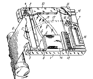
The he3d comprises a flat substrate 1 (Fig.1) made
of a dielectric material on the periphery of which is
accommodated-a magnetic circuit 2 haYing the form of a
frame made from a thin-film material (0.1-1.0 ~m thick~,
one section 3 of the frame being encompassed by an
electric planar winding 4. The magnetic circuit ~ is
made of a magnetic with a clearly defined thermomagnetic
effect. O~e of sections 5 of the magnetic circuit 2 (one
of the frame edges~ faces a magnetic carrier-~ ~magnetic
tape~ and is disposed in parallel with the surface
i5 thereof. A source of electromagnetic radiation, a
modulated laser diode ~, is installed on the section of
- the substrate 1 opposite to the magnetic oircuit 2.
Disposed over the magnetic circuit 2 and a larger
portion of the substrate 1 is a planar waveguide ~
~0 ~light guide~ used for communicating the section S of
the magnetic circuit 2 with the diode ~.
The waveguide 8 has the wid~h equal at least t~ the
length of the section 5 of the magnetic ~ir~uit ~ and is
provided with focusing plano-cylinder lenses ~, 10, 11.
The head is also provided with a scannin~ element 12 in
the form of acoucto-optic deflector based or. a~
op~osite-post resonator-exciter o~ surfase 3c0l1~tic
2155003
waves. The scsnning element 12 is installed on tne
substrate 1 so that the axis of electromagnetic
radiation at the exit from the lens 9 is disposed at a
~ragg angle to the front of surface acoustic zones. A~
absorber 13 of surface a~oustic ~aves is installed on
the substrate 1 opposite to the scanning element 12.
Also installed on the substrate 1 is an automatic
tracking controller 14 the outputs of which are
eleotric~lly associated with the winding 4, the diode 7
lo and the deflector 12. At the top the head is covered
with a housing 15 of a glassy material providing the
sealing and meGhanical protection of the units installed
on the head. A contact pad 16 for input of the power
supply and output of the head signals is pro~ided at the
1~ edge of the ~ubstrate 1.
The head functions in the following manner.
Reoording mode. Upon delivery of the eleGtric power
to the laser diode ',' a aoherent radiation 1,' emitted
therefrom passes through the planar w~veguide 8 made
from a transp3~ent material, for example~ lithium
niobate, which possesses alearly defined piezoeleotric
properties. Formed in this material by the method of
hydrogen exoh3n~e ~diffusion of Ti or by other methods~
are optical elements ~, iO, 11 3nd a "bending" edge of
the light guide 8 contributing to getting a ls~er
radi~tion spot 13 with a sufficient degree of focusing
onto the section 5 of the magnetic circuit 2. As a
- 2155003
- 12 -
magnetic featuring a relatively low Curie point, a high
induction of saturation, low rem~gneti~ation losses in
weak fields, low Barkhausen effeGt along with a high
permeance with its sharp drop ne~r Curie point, then the
loaal overhe3ting ~T ~ T~urie) induces a virtual gap C.
The virtual gap C is essentially a small-size area ~ith
- disturbed permeance of a nomogeneous m~terial of the
permanently clos~d magnetia circuit 2 ~Figs 2-4).
As the appliaation of an electria reaording signal
1~ to the winding 4 induces a magnetic field whose alosed
magnetic lines of forae are concentrated in the magnetic
cirauit 2~ the ~oraed local disturban~e of the magnetic
cirauit permeance aontributes' to the "flyout" of
the magnetic lines of forae into the nearby magnetia
- 15 carrier 6 tFig.4).
Formation of magnetic domains in the information-
-bearing signal trace of the moving aarrier ~, with
the virtual gap C remaining stationary results in a
longitudinal single-track reaording.
Changing the reaording format into ~ helical and
transverse formats is attain~ble by w~y of scanning the
virtual gap C along the seation 5' of the magnetic
cirauit 2 the edge of whiah is parallel to the plane
o~ the c.~rrier (m~gnetiG l~yer~. The l~tter is disposed
25 at a small distsnce and more fre~uently i9 in a
direct mechanical contact with the edge of the magnetia
aircuit 2 and with side end face of the head substrate 1
215500~
- 13 -
Scanning of the beam (Fig.3) emitted from the laser
diode 7 is effeated by the optoelectronic method
~use may be made of electro-optical deflectors or
deflectors based on other principles). Modulation of` the
eleat~ul"a~lletic radiationl the laser diode ~, and
functioning of the deflector 12 is synchronized
by an integrated circuit of the automatic tracking
controller 13. In the deflector 12 the frequency and
geometric parameters of the opposite-post resonator are
selected on the basis of acousto-optical characteristics
of the deflector 12 calculated in compliance with -the
standard procedure. The resonator parameters define a
scnic wave period and length which should be comparable
with the length of a radiation waYe, that is 3bout
0.8-1.6 ~m which corresponds to an excitation frequency
of ~00-iO00 M~z. The resonator band is selected with due
regard to a required deviation for a required angle of
defection of the laser diffracted beam.
R~3ding mode. The pro&esses going on in t~,e
optoelectroni~ portion of the head are 3nalogous to the
prw esses taking place during recording (~ith the
dif.'erence related to the clock signals at the input of
the automatic tr3cking controller 14 - the signals are
coming from the c~rrier 6~. The electric winding 4 of
the head in this mode is connected into the input of an
external ampiifier cf the playback signals and induces
the EMF from the field of the information-~e3ring signal
215SOO~
- 14 -
trace on the carrier 6.
The general oondition for effecting the record/read
modes resides in limiting the size of a spot of the
laser radiation 1~ on the section 5 of the magnetia
circuit 2 by the width thereof. The optical el~ments 9,
10, 11 used as the focusing-collimating me3ns provide
the diameter of tAe- spot of the laser radiation 1.
or the width of an ellipse from 1 to 10 ~m (depending
upon the indicated width of the magnetic circuit 2).
lQ C~pabilities of the diffusion te&hnology of the optical
- elements 9, 10, 11 ~the hydrogen ex&hange th~ough a
mask - for lithium ~niobate~ provides a step~ise
variation of a relative refractive index for an extra-
ordinary wave dNe = 0.12 and for an ordinary w~ve
dNo = -Q.004. For introdu~ing the radiation 1~ Q~ the
laser diode ~ in a ~veguide layer use may be made of
one widely known methods, for exampl~, end face,
diffraction, etc.
Evaluation of the technical characteristics of the
proposed method for information recording on and reading
from a magnetic carrier and a recording head for
effecting the ~ame when its working process is subjected
to the physicomsthem~tiaal simulation pro~es that the
method is efficient and fit for service in compa~ison
with the known standards. The attainable high density ~f
submicron lines from lD00 to 10,000 line/mm defined by a
smsll thickness of the film msgnetic circuit 2 amounting
215500~
-
-- 15 --
to 0.1-1.0 ~m makes it possible to obtain a surface
density of up to 10 Mbit per sq.mm for 1 ~m zone of the
Yirtual gap, thereby providing the volume of information
on a standard recorded tape in a VHS cassette in an
~mount over 10 Tbit (10,000,000,000,000 bit~. The speed
of scanning of the virtual gap may re~ch 1000 m~s ~with
account of the heat circulation and aotually in the
absenoe of wear of the tape and head~, thereby defining
a very high rate of the information flow (up to
500 Mbit/s) not attainable for other methods of
scanning. I~A~-~Ich as the rapid lo&al heating arld the
necessary scanning of the hot spot is effected by means
of the laser diode ~ with the use of the a~ousto-optical
deflector and the linear optic elements have ~een made
following the diffusion planar technology in the
integrated piezoelectric planar light guide~ then it
will be understood that there is a combination of new
functional ca~3bilities of the device with a high
fabric3bility thereof. The he3d is provided Wit~
one-chip microcirGuit of the automatio tracking
controller which controls the resonator of the de~lector
insuring the scanning of the gap by the lines of a
c~rrier moving forwsrd and in reYerse, ~nd when the
carrier is stopped.
~iven herein3fter i9 a oomp3rati~e table of the
basic indicators specified in the modern interna~ional
standards for reoordin~ and reading inform~tion and the
21~5003
- 16 -
indicators of the proposed method.
System: S-DAT R-DAT VYS FDD YDD E-DAD Proposed
density of` method
information
Longitudinal,
~bit/mm 2.5 ~.4 2.20.13 1.8 1.2 3
Surfaae,
kbitfsq.mm 32 128~ 49 1.5 16 ~20 lO,O~Q
Volume,
M~it/sq. mm 2 g 1.1~.00~ ~.003 0.6 20Q
~ata flow
rate,
Mbit/s 1.2 1.5 4 0.5 24 1.4 ~00
Industrial Applic3bility
The present invention may be used in the aomputer
technology, prcfessional and household apparatuses of
the audio and video recording, in systems of two-way
c3ble television with the regeneration of the video
information ~interative television).
The proposed invention makes it possible to obtain
a perspeotive technical means for digital registration
10 of video inf&rrna~i..rl for mass syst~ms ~nd syst~ ul
digital reaording for a high-definition television.
,, 2155003
- 17 -
~esigned for operation on standard magnetic carriers and
imparted with high design, operational and aost
characteristics, the proposed system is also intended
for use in external mass storage units with a random
access in the block addressing mode and with an assigned
format in the archival storage. The use of the main
principle of the method is promising for realizing
information disk storage units with an inoreased density
of the lines, a required quality of the line tracking
and with an ultrafast random access, as well as for
other devices which -by the mentioned parameters may
surpass the optical and magneto-optical disk-type
devices for recording, storing and reading information.
This is attained by using the main principle af the head
which eliminates a definite spatial diffraction
limitations inherent to direct optical systems.