Language selection

Search

Patent 2155373 Summary

Third-party information liability

Some of the information on this Web page has been provided by external sources. The Government of Canada is not responsible for the accuracy, reliability or currency of the information supplied by external sources. Users wishing to rely upon this information should consult directly with the source of the information. Content provided by external sources is not subject to official languages, privacy and accessibility requirements.

Claims and Abstract availability

Any discrepancies in the text and image of the Claims and Abstract are due to differing posting times. Text of the Claims and Abstract are posted:

  • At the time the application is open to public inspection;
  • At the time of issue of the patent (grant).
(12) Patent: (11) CA 2155373
(54) English Title: COMPACT MOTOR CONTROLLER ASSEMBLY
(54) French Title: ENSEMBLE COMPACT DE COMMANDE MOTEUR
Status: Term Expired - Post Grant Beyond Limit
Bibliographic Data
(51) International Patent Classification (IPC):
  • H02K 05/00 (2006.01)
  • H02B 11/173 (2006.01)
(72) Inventors :
  • JOYNER, ROBERT D. (United States of America)
  • HARRISON, JERROLD J. (United States of America)
(73) Owners :
  • GENERAL ELECTRIC COMPANY
(71) Applicants :
  • GENERAL ELECTRIC COMPANY (United States of America)
(74) Agent: CRAIG WILSON AND COMPANY
(74) Associate agent:
(45) Issued: 2004-11-02
(22) Filed Date: 1995-08-03
(41) Open to Public Inspection: 1996-02-25
Examination requested: 2002-07-25
Availability of licence: N/A
Dedicated to the Public: N/A
(25) Language of filing: English

Patent Cooperation Treaty (PCT): No

(30) Application Priority Data:
Application No. Country/Territory Date
08/295,138 (United States of America) 1994-08-24

Abstracts

English Abstract

High voltage motor contactors and associated equipment are arranged within upper and lower compartments that are interlocked with the external operator handle to prevent access when the contactors are electrically energized. Low voltage devices used in association with the contactors to provide total motor control function are housed within upper and lower cabinets arranged on the upper and lower compartment doors. An interlock defeat assembly is mounted within the low voltage cabinets to allow emergency access to the compartments while the contactors are still energized.


French Abstract

Des contacteurs de moteur haute tension et équipements associés sont disposés dans des compartiments supérieur et inférieur qui sont inter-verrouillés avec la poignée de commande externe pour empêcher l'accès lorsque les contacteurs sont alimentés électriquement. Des appareils basse tension utilisés en association avec les contacteurs pour fournir une fonction de commande de moteur totale sont logés à l'intérieur des armoires supérieure et inférieure disposées sur les portes de compartiments supérieure et inférieure. Un ensemble de mise en échec de verrouillage est monté à l'intérieur des armoires basse tension pour permettre un accès d'urgence aux compartiments alors que les contacteurs sont encore sous tension.

Claims

Note: Claims are shown in the official language in which they were submitted.

CLAIMS
1. A motor controller unit comprising:
an enclosure 10;
a compartment 13 within said enclosure, said
compartment containing a motor contactor unit 21;
an operating handle 16 controlling ON and OFF
states of said contactor, said operating handle
including a handle operator 17 extending outside said
compartment providing external access thereto;
a compartment door 15 on said compartment for
deterring access to said contactor unit;
a cabinet 27 arranged on an outer surface of said
compartment door, said cabinet containing equipment
31 electrically connecting with said contactor;
a cabinet door 30 on said cabinet for deterring
access to said equipment;
an interlock lever 39 interacting with said handle
and said compartment door for preventing movement of
said door to an open position when said handle
operator is in an ON position; and
an interlock defeat mechanism 50 accessible from
within said cabinet for unlatching said interlock and
allowing movement of said compartment door to said
open position.
2. The motor controller unit of claim 1 including a
handle prate 42 contacting said interlock lever 39 to
thereby prevent said compartment door from opening
when said handle operator is in said ON position.
7

3. The motor controller unit of claim 1 wherein
said defeat mechanism comprises a plate 32 slidably
mounted within said cabinet on a front surface of
said compartment door.
4. The motor controller unit of claim 3 including a
defeat lever 34 on said plate extending through said
compartment door.
5. The motor controller unit of claim 4 wherein
said defeat lever interferes with said interlock
lever to prevent opening said compartment door when
said handle operator is in said ON position.
6. The motor controller unit of claim 5 wherein
said defeat lever is biased against said interlock
lever by means of a spring 36.
7. The motor controller unit of claim 6 including
plate fastening means 33 holding said plate against
said front surface of said compartment door.
8. The motor controller unit of claim 1 wherein
said cabinet door is prevented from rotating away
from said cabinet by cabinet door fastening means 29.
9. The motor controller unit of claim 1 wherein
said compartment door is prevented from rotating away
from said compartment by compartment door fastening
means 28.
10. A method of controlling access to components
contained within a motor controller unit comprising
the steps of:
providing a compartment containing a motor
8

contactor; arranging a compartment door on said
compartment preventing access to said contactor;
arranging a cabinet containing electrical components
on an outer surface of said compartment door;
arranging a cabinet door on said cabinet preventing
access to said components; providing an interlock
lever on said compartment door to prevent access to
said contactor when said contactor is energized; and
arranging interlock lever defeating mean; within said
cabinet to allow access to said energized contactor
by a skilled operator.
9

Description

Note: Descriptions are shown in the official language in which they were submitted.


41 P 807206
COMPACT MOTOR CONTROLLER ASSEMBLY
BACKGROUND OF THE INVENTION
5 Motor controller equipment generally includes
so-called "high voltage" motor contactors such as
described within U.S. Patent 3,198,910 entitled
"Electromagnetic Relay Having Removable Contact and
Coil Assemblies" as well as "low voltage" equipment
l0 in the form of relays and the like. One such relay
being that described within U.S. Patent 5,057,962
entitled "Microprocessor Based Protective Relay
System".
The motor controller equipment is interlocked
15 with the externally accessible handle operator to
prevent access to the high voltage equipment when the
operating handle is in the ON position. U.S. Patent
4,760,220 entitled "Operator Mechanism Having
Reduced Handle Throw,and Improved Handle Lock" is one
20 example of such an interlock.
The state o.f the art of such motor controller
equipment is to mount the low voltage equipment in
cabinets having a separate access door from that of
the high voltage contactor within a separate
25 compartment to allow ready access~to the low voltage
equipment without having to turn off the contactor.
U.S. Patent 3,621,339 entitled "Modular High Voltage
Electrical Components Cooperating Within Cabinet
Housing to Provide Electrical Insulation and Cooling
3o Air Passage" describes the separate arrangement of
the high voltage contactors and low voltage
equipment.
1

41P 807206
2~.~ i3 ~ 3
It has been determined that emergency access to
the high voltage contactors may be required while
such contactors are in the ON condition and that the
handle interlock arrangement should be defeated
5 without damaging the equipment enclosure.
Accordingly, one purpose of the invention is to
provide means for a skilled operator to access the
high voltage contactor compartment under emergency
conditions while the contactor is energized.
l0
SUMMARY OF THE INVENTION
The invention comprises accessible low voltage
and inaccessible interlocked high voltage motor
controller equipment within a common enclosure. An
15 interlock defeat assembly is mounted within the low
voltage equipment part of the enclosure to allow
emergency access to the high voltage equipment while
the equipment is still energized.
20 BRIEF DESCRIPTION OF THE DRAWINGS
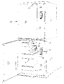
Figure 1 is a front perspective view of a motor
controller equipment enclosure containing the
interlock defeat mechanism according to the
invention;
25 Figure 2 is a front perspective view of the
motor controller equipment enclosure of Figure 1 with
the high voltage compartment door in the open
position while the equipment is energized; and
Figure 3 is an enlarged top perspective view of
30 the operator handle assembly contained within the
equipment enclosure of Figures 1 and 2.
2

41 PR07206
DESCRIPTION OF THE PREFERRED EMBODIMENT
The emergency accessible motor control center of
the invention is depicted at 10 in Figure 1 and
includes a sheet metal enclosure 11 having top and
5 bottom high voltage contactor compartments 12, 13.
"High voltage" for purposes of this disclosure is
voltage in excess of one thousand volts. The
compartments are accessed by means of the top and
bottom compartment doors 14, 15 respectively and the
to handle assembly 16 provides control of the equipment
contained therein by means of the externally -
accessible handle operator 17. The top and bottom low
voltage cabinets 25, 26, contain the low voltage
components 31 which may consist of relays, switches,
15 alarms and the like. The low voltage cabinets are
covered by doors 26, 30 which are fastened to the
enclosure 11 by means of bolts 29. The bottom low
voltage cabinet 27 is depicted with the door 30 open
to show the high voltage interlock defeat assembly 50
2o in the fona of a slidably mounted release plate 32
that carries the interlock defeat lever 34 projecting
through the slot 35, as indicated. The return spring
36 connects with the release plate at one end and
with the interior of the cabinet at the other end as
25 indicated at 37. To access the interior of the
associated bottom high voltage compartment 13 by
means of the door 15 with the handle operator 17 in
the ON position, and with the associated high voltage
equipment electrically energized, the bolts 28 on the
3o high voltage door 15 are removed, the low voltage
cabinet door 30 is opened by removing the bolts 29,
and the interior of the cabinet is exposed to provide
access to the interlock defeat assembly 50. The bolts
33 holding the release plate 32 are then removed
3

41 PR07206
allowing the release plate to be moved upwards, as
viewed in Figure 1, against the urgence of the return
spring 36.
The release plate 33 carries the defeat lever
5 34, which extends through the slot 35, away from the
interlock lever 39 as best seen by now referring
j ointly to the control center 10 shown in Figures 1
and 2 as well as to the handle assembly 16 shown in
Figure 3. With the bottom high voltage door 15 in the
l0 closed position against the enclosure 11, as shown
earlier, the end 34A of the defeat lever 34
interferes with the interlock lever 39 to prevent
the door 15 from swinging away from the enclosure 11
while the handle operator is in the upwards ON
15 position. This is caused by the contact between the
tab 42A extending downward from the handle plate 42
and the interlock lever 39. When the handle operator
is moved downward to the OFF position, the lever 39
is spring-loaded upwards away from the end 34A of the
20 defeat lever 34 to allow the door to rotate to the
open position. With the bolts 33 removed from the
release plate 34 to access the interior of the
compartment 13, as described earlier, an operator can
then move the release plate upwards while at the
25 same time pulling on the compartment door 15 to swing
the compartment door to the open position.
The .operating handle assembly 16 is shown in
Figure 3 positioned on an angular support frame 41.
The assembly includes a plastic guide assembly 40
30 that is attached to the housing by means of a
metallic bracket 51 and is arranged such that when
the bracket is attached to the interior of the bottom
high voltage compartment 13 of Figure 2 the handle
operator 17 extends through the handle slot 18 formed

41 PR07206
within the compartment door 15. The handle plate 42
pivotally attached to the bottom of the handle
operator, extends through a slot 43 formed in the
support frame and connects with a horizontal lever 44
5 which, in turn attaches to one end of a bell crank
lever 45 which is pivotally attached to the off-set
end 53 of the support frame 41. A vertical lever 46
attaches to the disconnect switch (not shown) that
provides electric power to the motor contactor unit
l0 21 of Figure 2. Also shown in Figure 2 are the
terminals 22 that connect the interior components
with external equipment such as motors and the like
by means of the multi-conductor cable 23 that exits
the bottom 24 of the compartment 13. Referring back
15 to Figure 3, a plurality of modular switches 48 with
actuating buttons 49 are positioned on the support
frame 41 and connect with remote accessories such as
indicating lamps, bell alarms and the like depending
upon user requirements. An interlock rod 54 and
20 interlock assembly 55 interact with the horizontal
rod 44 to prevent movement of the handle operator 17
when the compartment door 15 of Figure 1 is opened in
accordance with the teachings of the prior art. The
advantage of the handle assembly 16 over the prior
25 art is the modularity of the handle operating
components on the common support frame 41 which
closely controls the tolerances of the individual
components and allows the handle assembly to be
adjusted prior to attachment within the associated
3o high voltage compartment.

41 PR07206
In accordance with the invention, an arrangement
has herein been described whereby the low voltage
components of a motor controller unit are contained
in a separate cabinet for easy access apart from the
5 high voltage components. An interlock defeat
mechanism is arranged whereby a skilled operator can
access the high voltage compartment for observation
and repair without having to turn off the high
voltage components. The handle assembly is described
to in modular format for off-line assembly and testing
as well as to control the tolerance of the handle
operator components.
6

Representative Drawing
A single figure which represents the drawing illustrating the invention.
Administrative Status

2024-08-01:As part of the Next Generation Patents (NGP) transition, the Canadian Patents Database (CPD) now contains a more detailed Event History, which replicates the Event Log of our new back-office solution.

Please note that "Inactive:" events refers to events no longer in use in our new back-office solution.

For a clearer understanding of the status of the application/patent presented on this page, the site Disclaimer , as well as the definitions for Patent , Event History , Maintenance Fee  and Payment History  should be consulted.

Event History

Description Date
Inactive: Expired (new Act pat) 2015-08-03
Inactive: IPC from MCD 2006-03-11
Grant by Issuance 2004-11-02
Inactive: Cover page published 2004-11-01
Inactive: Final fee received 2004-08-19
Pre-grant 2004-08-19
Notice of Allowance is Issued 2004-03-30
Letter Sent 2004-03-30
Inactive: Approved for allowance (AFA) 2004-03-10
Inactive: Application prosecuted on TS as of Log entry date 2002-09-06
Letter Sent 2002-09-06
Inactive: Status info is complete as of Log entry date 2002-09-06
Amendment Received - Voluntary Amendment 2002-07-25
All Requirements for Examination Determined Compliant 2002-07-25
Request for Examination Requirements Determined Compliant 2002-07-25
Application Published (Open to Public Inspection) 1996-02-25

Abandonment History

There is no abandonment history.

Maintenance Fee

The last payment was received on 2004-07-29

Note : If the full payment has not been received on or before the date indicated, a further fee may be required which may be one of the following

  • the reinstatement fee;
  • the late payment fee; or
  • additional fee to reverse deemed expiry.

Patent fees are adjusted on the 1st of January every year. The amounts above are the current amounts if received by December 31 of the current year.
Please refer to the CIPO Patent Fees web page to see all current fee amounts.

Owners on Record

Note: Records showing the ownership history in alphabetical order.

Current Owners on Record
GENERAL ELECTRIC COMPANY
Past Owners on Record
JERROLD J. HARRISON
ROBERT D. JOYNER
Past Owners that do not appear in the "Owners on Record" listing will appear in other documentation within the application.
Documents

To view selected files, please enter reCAPTCHA code :


To view images, click a link in the Document Description column. To download the documents, select one or more checkboxes in the first column and then click the "Download Selected in PDF format (Zip Archive)" or the "Download Selected as Single PDF" button.

List of published and non-published patent-specific documents on the CPD .

If you have any difficulty accessing content, you can call the Client Service Centre at 1-866-997-1936 or send them an e-mail at CIPO Client Service Centre.


Document
Description 
Date
(yyyy-mm-dd) 
Number of pages   Size of Image (KB) 
Representative drawing 1998-04-15 1 19
Claims 1995-08-02 3 76
Description 1995-08-02 6 211
Abstract 1995-08-02 1 18
Drawings 1995-08-02 3 72
Claims 2002-07-24 3 91
Representative drawing 2004-03-10 1 10
Reminder - Request for Examination 2002-04-03 1 119
Acknowledgement of Request for Examination 2002-09-05 1 177
Commissioner's Notice - Application Found Allowable 2004-03-29 1 161
Correspondence 2004-08-18 1 26