Language selection

Search

Patent 2155469 Summary

Third-party information liability

Some of the information on this Web page has been provided by external sources. The Government of Canada is not responsible for the accuracy, reliability or currency of the information supplied by external sources. Users wishing to rely upon this information should consult directly with the source of the information. Content provided by external sources is not subject to official languages, privacy and accessibility requirements.

Claims and Abstract availability

Any discrepancies in the text and image of the Claims and Abstract are due to differing posting times. Text of the Claims and Abstract are posted:

  • At the time the application is open to public inspection;
  • At the time of issue of the patent (grant).
(12) Patent Application: (11) CA 2155469
(54) English Title: TRANSMISSION FOR AN ACTUATING DRIVE HAVING A SPRING RETURN FEATURE
(54) French Title: TRANSMISSION POUR MECANISME D'ENTRAINEMENT A RAPPEL PAR RESSORT
Status: Deemed Abandoned and Beyond the Period of Reinstatement - Pending Response to Notice of Disregarded Communication
Bibliographic Data
(51) International Patent Classification (IPC):
  • F24F 13/10 (2006.01)
  • F16H 03/00 (2006.01)
  • F16H 19/00 (2006.01)
  • F16K 31/04 (2006.01)
  • F16K 31/53 (2006.01)
(72) Inventors :
  • BIRCHMEIER, WERNER (Switzerland)
(73) Owners :
  • WERNER BIRCHMEIER
(71) Applicants :
(74) Agent: AVENTUM IP LAW LLP
(74) Associate agent:
(45) Issued:
(22) Filed Date: 1995-08-04
(41) Open to Public Inspection: 1996-02-18
Examination requested: 2002-07-31
Availability of licence: N/A
Dedicated to the Public: N/A
(25) Language of filing: English

Patent Cooperation Treaty (PCT): No

(30) Application Priority Data:
Application No. Country/Territory Date
94 112 826.6 (European Patent Office (EPO)) 1994-08-17

Abstracts

English Abstract


The invention relates to a transmission for a
spring return actuator The transmission comprises a
drive pinion (2) associated with the actuator, an
intermediate pinion (5) meshing with the drive pinion
(2), an output shaft (3) with a clutch (4) for a final
control element, and two wheels (6, 7) disposed on the
same spindle. The wheels (6, 7) have respective
external toothing (8, 9) and a respective rotatably
mounted hub (10, 11) which extends with the
interposition of an annular gap around the output shaft
(3). The drive pinion (2) is in engagement with the
external toothing (8) of one of the two wheels. The
intermediate pinion (5) engages in the external
toothing (9) of the other wheel. A clutch sleeve (14)
is disposed in the annular gap between the output shaft
(3) and the wheels (6, 7), is releasably connected to
the output shaft (3) and is in positive engagement with
the hub (10, 11) of one of the wheels (6 or 7). The
directlon of rotation of the output shaft (3) can be
changed by changing the clutch sleeve (14). - Fig. 1.


Claims

Note: Claims are shown in the official language in which they were submitted.

- 8 -
C L A I M S
1. A transmission for a spring return actuator, the
transmission comprising
a drive pinion (2) associated with the actuator,
an intermediate pinion (5) meshing with the drive
pinion (2),
an output shaft (3) with a clutch (4) for a final
control element, and
two wheels (6, 7) disposed consecutively on the
same spindle and having respective external
toothing (8, 9) and a respective rotatably mounted
hub (10, 11) which extends with the interposition
of an annular gap around the output shaft (3),
wherein the drive pinion (2) is in engagement with the
external toothing (8) of one of the two wheels and the
intermediate pinion (5) engages in the external
toothing (9) of the other wheel, and wherein a clutch
sleeve (14) is disposed in the annular gap between the
output shaft (3) and the wheels (6, 7) and is
releasably connected to the output shaft (3) and is in
positive engagement with the hub (10, 11) of one of the
wheels (6 or 7).
2. A transmission according to claim 1, wherein the
hubs (10, 11) of the wheels (6, 7) each have an
internal toothing (15) engageable with a toothed ring
(18) on the periphery of the clutch sleeve (14).

- 9 -
3. A transmission according to claim 2, wherein the
clutch sleeve (14) has a plain cylindrical part (17)
into which the toothed ring (18) merges and which is
rotatable relatively to the hub (10, 11) of the wheels
(6, 7).
4. A transmission according to any of claims 1 to 3,
wherein the clutch sleeve (14) is secured in the axial
direction by means of a detent spring (18) secured to
the output shaft (3).
5. A transmission according to any of claims 1 to 4,
wherein the wheels (6, 7) comprise the hub (10, 11) and
a circle-segment disc (12, 13) on whose periphery the
external toothing (8, 9) is disposed.

Description

Note: Descriptions are shown in the official language in which they were submitted.


2I554 69
D e s c r i p t i o r
The invention relates to a transmission for a
spring return actuator.
Spring return actuators are widely used to operate
final control elements, more particularly valves, in
heating, air conditioning and ventilation systems.
Actuators of this kind, which will be referred to
hereinafter as spring return actuators, comprise a
return spring which is cocked by a motor having a
reduction transmission. The energy stored in the
return spring is released when the electric motor
becomes currentless. The spring return feature ensures
that in the event of a power failure the final control
element moves into a safety position, normally its
closed position.
In practice the actuators are fitted on the left
and on the right of final control elements, for
example, ventilation valves. The choice of side for
assembly depends upon space conditions in an existing
system. However, the direction of rotation of a valve
alters with a change of the assembly side. If, for
example, a valve opens clockwise for example, when
considered from the left, it opens anticlockwise when
considered from the right.
Spring return drives usually have just a single
return spring. The spring return feature and the
direction of rotation of the actuator output shaft
associated with the final control element are fixed.

2155469
-- 2 --
Known actuators are always associated with one
particular assembly direction.
It is known to turn the output shaft to be
connected to the final control element through 180 for
adaptation to the direction of valve rotation.
However, this feature is nearly always offset by the
disadvantage that after the output shaft has been
turned the control and connection parts, such as
auxiliary switches, manual winding-up, connection
terminals, circuit boards and so on are accessible only
with di ff iculty, if at all.
It is the object of the invention to disclose a
transmission for a spring return drive which enables
the direction of rotation of the output shaft
associated with the final control element to be
reversed.
The subject of the invention and the solution of
this problem is a transmission comprising
a drive pinion associated with the actuator,
an intermediate pinion meshing with the drive
pinion,
an output shaft with a clutch for a final control
element, and
two wheels disposed axially consecutively on the
same spindle and having respective external
toothing and a respective rotatably mounted hub

2155~ S9
-- 3 --
which extends with the interposition of an annular
gap around the output shaft,
wherein the drive pinion is in engagement with the
external toothing of one of the two wheels and the
intermediate pinion engages in the external toothing of
the other wheel, a clutch sleeve is disposed in the
annular gap between the output shaft and the wheels and
is releasably connected to the output shaft and is in
positive engagement with the hub of one of the wheels.
The intermediate pinion driven by the drive pinion
rotates in the opposition direction thereto.
Consequently, the tr~n~ iSsion according to the
invention has two wheels which rotate synchronously in
time with the drive pinion but in different directions.
The clutch sleeve is replaceable and represents, as it
were, a control element which transmits at choice the
movement of one or the other wheel to the output shaft
associated with the final control element. The clutch
sleeve requires no mounting of its own in the casing
and is therefore readily exchangeable.
Various constructive solutions present themselves
for the further development of the transmission
according to the invention. In a preferred
construction of the transmission according to the
invention, the hubs of the wheels each have an internal
toothing engageable with a toothed ring on the
periphery of the clutch sleeve. This construction
ensures uniform transmission of the tor~ue. According
to another feature of the invention, the clutch sleeve
has a plain cylindrical part into which the toothed

2155~ 69
-- 4 --
ring merges and which is rotatable relatively to the
hub of the wheels. Conveniently, the hubs of the two
wheels driven by the drive pinion or intermediate
pinion are identical - i.e., they have identical
sions and identical toothing. The clutch sleeve
extends through the annular gap bounded by the two
hubs, one half of the clutch sleeve being formed with a
toothed ring corresponding to the internal toothing of
the hubs while the other half is a plain cylindrical
part. The clutch sleeve is selectively introducible
into the annular gap between the hubs and the output
shaft at the casing end near the final control element
or at the casing end remote therefrom. Preferably, a
detent spring secured to the output shaft is provided
to secure the clutch sleeve.
The operative movement of the spring return drive
is usually so limited that the output shaft performs
angular movements of at most 180, the rotation being
clockwise or anticlockwise dep~n~ing upon how the
clutch sleeve is fitted. The wheels comprise the hub
and a circle-segment disc on whose periphery the
external toothing is disposed. The alignment of the
circle-segment disc and the length of the circle-arc
segment are adapted to the operative movement of the
spring return drive and to the direction of output
shaft rotation.
The invention will be described hereinafter with
reference to drawings which illustrate merely one
embodiment and in which in diagrammatic form:

215~ ~9
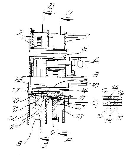
Fig. 1 is a longitudinal sectior. through the
transmission according to the invention;
Fig. 2 is a section on the line A-A of Fig. 1, and
Fig. 3 is a section on the line B-B of Fig. 1.
The transmission shown in the drawings is for a
spring return actuator. The basic structure of the
transmission comprises a casing 1 connectable to the
spring return actuator, a drive pinion 2 associated
with the actuator and an output shaft 3 with a clutch 4
for a final control element (not shown). The final
control element can be a valve in a heating or air
conditioning or ventilation system.
The transmission also has an intermediate pinion 5
~h;ng with the drive pinion 2 and two wheels 6, 7
disposed on the same spindle. The wheels 6, 7 each
have external toothing 8, 9 and a hub 10, 11 which
extends around the output shaft 3 with the
interposition of an annular gap. The wheels 6, 7 are,
like the gearwheels 2, 5 and the shaft 3, rotatably
mounted in the casing 1.
Figs. 2 and 3 are a plan view of the wheels 6, 7
and illustrate the kin^ -tics of the arrangement. The
wheels 6, 7 comprise the hub 10, 11 and a circle-
segment disc 12, 13 on whose periphery the external
toothing 8, 9 is disposed. The drive pinion 2 is in
engagement with the external toothing 8 of one wheel 6
and the intermediate pinion 5 engages the external
toothing 9 of the other wheel 7. Since the drive

2155~69
pinion 2 drives the pinion 5 the same rotates in the
opposite direction to the pinion 2. The wheels 6, 7
move synchronously but in different directions of
rotation. The movement patterns are indicated by
arrows in Figs. 2 and 3. When the pinion 2 rotates
clockwise the wheels 6, 7 move in the -nner shown into
the operative positions shown in chain-dotted lines.
The angle a through which they move is 93 in the
embodiment.
As can be gathered from Fig. 1, a clutch sleeve 14
is disposed in the annular gap between the output shaft
3 and the wheels 6, 7, is releasably connected to the
output shaft 3 and is in positive engagement with the
hub of one of the wheels, in this case the hub 11 of
the wheel 7. The coaxially mounted wheels 6, 7 each
have on the hub side an internal toothing 15 engageable
with a toothed ring 16 on the periphery of the sleeve
14. The resulting positive connection serves to
transmit the torque to the output shaft 3 by way of the
sleeve~l4. The same also has a plain cylindrical part
17 into which the toothed ring 16 merges and which is
rotatable relatively to the hub of the wheels, in this
case to the hub 10 of the wheel 6. If, as shown in the
embodiment, the output shaft 3 is to rotate in the same
direction as the wheel 7, the half-toothed sleeve 14 is
introduced into the annular gap from the casing end
facing the clutch 4 and is secured in the position
shown by means of a detent spring 18 secured to the
output shaft 3. The toothed ring 16 and the internal
toothing lS on the hub 11 of the wheel 7 provide a
positive connection which transmits the torque from the
wheel 7 to the output shaft 3. The oppositely driven

2155~69
wheel 6 runs freely on the plain cylindricai part 17 of
the sleeve 14. If the shaft 3 is required to rotate in
the same direction as the wheel 6, the sleeve 14 is
removed and introduced into the annular gap from the
casing end remote from the clutch 4. In this case the
drive is from the other wheel 6 by way of the sleeve 14
to the output shaft 3.

Representative Drawing
A single figure which represents the drawing illustrating the invention.
Administrative Status

2024-08-01:As part of the Next Generation Patents (NGP) transition, the Canadian Patents Database (CPD) now contains a more detailed Event History, which replicates the Event Log of our new back-office solution.

Please note that "Inactive:" events refers to events no longer in use in our new back-office solution.

For a clearer understanding of the status of the application/patent presented on this page, the site Disclaimer , as well as the definitions for Patent , Event History , Maintenance Fee  and Payment History  should be consulted.

Event History

Description Date
Inactive: Adhoc Request Documented 2018-06-06
Revocation of Agent Requirements Determined Compliant 2018-05-18
Appointment of Agent Requirements Determined Compliant 2018-05-18
Inactive: IPC from MCD 2006-03-11
Time Limit for Reversal Expired 2004-08-04
Application Not Reinstated by Deadline 2004-08-04
Inactive: Agents merged 2003-12-09
Deemed Abandoned - Failure to Respond to Maintenance Fee Notice 2003-08-04
Inactive: Status info is complete as of Log entry date 2002-08-19
Letter Sent 2002-08-19
Inactive: Application prosecuted on TS as of Log entry date 2002-08-19
All Requirements for Examination Determined Compliant 2002-07-31
Request for Examination Requirements Determined Compliant 2002-07-31
Application Published (Open to Public Inspection) 1996-02-18

Abandonment History

Abandonment Date Reason Reinstatement Date
2003-08-04

Maintenance Fee

The last payment was received on 2002-07-31

Note : If the full payment has not been received on or before the date indicated, a further fee may be required which may be one of the following

  • the reinstatement fee;
  • the late payment fee; or
  • additional fee to reverse deemed expiry.

Patent fees are adjusted on the 1st of January every year. The amounts above are the current amounts if received by December 31 of the current year.
Please refer to the CIPO Patent Fees web page to see all current fee amounts.

Fee History

Fee Type Anniversary Year Due Date Paid Date
MF (application, 2nd anniv.) - standard 02 1997-08-04 1997-07-18
MF (application, 3rd anniv.) - standard 03 1998-08-04 1998-07-20
MF (application, 4th anniv.) - standard 04 1999-08-04 1999-08-04
MF (application, 5th anniv.) - standard 05 2000-08-04 2000-08-02
MF (application, 6th anniv.) - standard 06 2001-08-06 2001-08-07
MF (application, 7th anniv.) - standard 07 2002-08-05 2002-07-31
Request for examination - standard 2002-07-31
Owners on Record

Note: Records showing the ownership history in alphabetical order.

Current Owners on Record
WERNER BIRCHMEIER
Past Owners on Record
None
Past Owners that do not appear in the "Owners on Record" listing will appear in other documentation within the application.
Documents

To view selected files, please enter reCAPTCHA code :


To view images, click a link in the Document Description column. To download the documents, select one or more checkboxes in the first column and then click the "Download Selected in PDF format (Zip Archive)" or the "Download Selected as Single PDF" button.

List of published and non-published patent-specific documents on the CPD .

If you have any difficulty accessing content, you can call the Client Service Centre at 1-866-997-1936 or send them an e-mail at CIPO Client Service Centre.


Document
Description 
Date
(yyyy-mm-dd) 
Number of pages   Size of Image (KB) 
Representative drawing 1999-06-22 1 20
Description 1995-08-03 7 204
Claims 1995-08-03 2 41
Abstract 1995-08-03 1 24
Drawings 1995-08-03 3 64
Reminder - Request for Examination 2002-04-07 1 119
Acknowledgement of Request for Examination 2002-08-18 1 177
Courtesy - Abandonment Letter (Maintenance Fee) 2003-09-01 1 176
Correspondence 1995-08-03 30 1,094
Fees 1998-07-19 1 37
Fees 2001-08-06 1 39
Fees 1997-07-17 1 37
Fees 1999-08-03 1 33
Fees 2000-08-01 1 33