Language selection

Search

Patent 2155479 Summary

Third-party information liability

Some of the information on this Web page has been provided by external sources. The Government of Canada is not responsible for the accuracy, reliability or currency of the information supplied by external sources. Users wishing to rely upon this information should consult directly with the source of the information. Content provided by external sources is not subject to official languages, privacy and accessibility requirements.

Claims and Abstract availability

Any discrepancies in the text and image of the Claims and Abstract are due to differing posting times. Text of the Claims and Abstract are posted:

  • At the time the application is open to public inspection;
  • At the time of issue of the patent (grant).
(12) Patent: (11) CA 2155479
(54) English Title: TAMPING UNIT FOR TRACK TAMPING MACHINES FOR TAMPING TWO IMMEDIATELY ADJACENT SLEEPERS
(54) French Title: ORGANE DE BOURRAGE POUR MACHINE TRAITANT SIMULTANEMENT DEUX TRAVERSES ADJACENTES
Status: Expired and beyond the Period of Reversal
Bibliographic Data
(51) International Patent Classification (IPC):
  • E01B 27/16 (2006.01)
(72) Inventors :
  • THEURER, JOSEF (Austria)
  • PEITL, FRIEDRICH (Austria)
(73) Owners :
  • FRANZ PLASSER BAHNBAUMASCHINEN-INDUSTRIEGESELLSCHAFT M.B.H.
(71) Applicants :
  • FRANZ PLASSER BAHNBAUMASCHINEN-INDUSTRIEGESELLSCHAFT M.B.H. (Austria)
(74) Agent: RICHES, MCKENZIE & HERBERT LLP
(74) Associate agent:
(45) Issued: 1999-04-20
(22) Filed Date: 1995-08-04
(41) Open to Public Inspection: 1996-02-10
Examination requested: 1995-08-29
Availability of licence: N/A
Dedicated to the Public: N/A
(25) Language of filing: English

Patent Cooperation Treaty (PCT): No

(30) Application Priority Data:
Application No. Country/Territory Date
A 1550/94 (Austria) 1994-08-09

Abstracts

English Abstract


A tamping unit (7) for track tamping machines for tamping
two immediately adjacent sleepers of a track is provided with
two pairs, mounted one following the other in the longitudinal
direction of the machine on a vertically adjustable tool
carrier (14,15), of outer and inner tamping tools (10-13)
respectively connected to an eccentric shaft (17,26) by way of
a squeeze drive (18,25). One of the outer tamping tools (13)
arranged on either side of the inner tamping tools (10,11) -
with respect to the longitudinal direction of the machine - is
designed so as to be independently vertically adjustable
relative to the other tamping tools (10,11,12) by means of a
separate vertical adjustment drive (20). This independently
vertically adjustable outer tamping tool (13) is mounted on a
separate, second tool carrier (15) and is connected by way of
the squeeze drive (18) to a separate eccentric shaft (17).
The associated tool carrier (15) is mounted for vertical
adjustment on a vertical guide (19) and is connected for the
vertical adjustment to the separate vertical adjustment drive
(20).


French Abstract

Cette invention concerne un organe de bourrage (7) sur bourreuse de voie étudiée pour le traitement de deux traverses immédiatement adjacentes. Il comprend deux paires de bourroirs, une paire de bourroirs extérieurs et une paire de bourroirs intérieurs (10-13), montées l'une derrière l'autre dans le sens longitudinal de la bourreuse sur un porte-outil réglable en hauteur (14, 15) et raccordées respectivement à un de deux arbres à excentrique (17, 26) au moyen d'un vérin (18, 25). Un des bourroirs extérieurs (13), monté d'un côté ou l'autre des bourroirs intérieurs (10, 11) - dans le sens longitudinal de la bourreuse -, est adapté pour se régler en hauteur indépendamment des autres bourroirs (10, 11, 12) au moyen d'un mécanisme de réglage en hauteur distinct (20). Ce bourroir (13) à réglage en hauteur indépendant est monté sur un porte-outil distinct (15) et raccordé au moyen d'un vérin (18) à un arbre à excentrique distinct (17). Ce porte-outil (15) est monté sur un guide vertical de réglage en hauteur (19) et raccordé à un mécanisme de réglage en hauteur distinct (20).

Claims

Note: Claims are shown in the official language in which they were submitted.

We claim:
1. A tamping tool assembly for tamping ballast
underneath no more than two successive ties of a railroad
track, which comprises,
two pairs of tamping tools succeeding each other in
the direction of elongation of the railroad track, two
proximal tamping tools of the pairs being adjacent each
other and two distal tamping tools of the pairs being
remote from each other and arranged at respective ends of
the assembly in said direction,
a first vertically adjustable tamping tool carrier,
a first crank shaft mounted on the first tamping
tool carrier,
drive means connecting the two adjacent proximal
tamping tools and one of the distal tamping tools to the
first crank shaft for reciprocating the two adjacent
proximal tamping tools and the one distal tamping tool in
the direction of elongation of the railroad track,
a first drive for vertically adjusting the first
tamping tool carrier for immersing the two adjacent
proximal tamping tools in the ballast between the two
successive ties and the one distal tamping tool in the
ballast adjacent one of the ties,
a second vertically adjustable tamping tool carrier
having an end face facing an end face of the first
tamping tool carrier,
a second crank shaft mounted on the second tamping
tool carrier,
drive means connecting the other distal tamping tool
to the second crank shaft for reciprocating the other
distal tamping tool in the direction of elongation of the
railroad track,
a vertical guide whereon the second tamping tool
carrier is mounted for vertical adjustment,
a second drive vertically adjusting the second
tamping tool carrier independently of the first tamping

tool carrier for immersing the other distal tamping tool
in the ballast adjacent the other one of the successive
ties.
2. The tamping tool assembly of claim 1, wherein the
second crank shaft is arranged remote from the end face
of the second tamping tool carrier.
3. The tamping tool assembly of claim 2, wherein the
vertical guide is arranged between the other distal
tamping tool and the second crank shaft.
4. The tamping tool assembly of any one of claims 1 to
3, further comprising a common carrier frame for the
tamping tool carriers, the vertical guide for the second
tamping tool carrier and vertical guide means for the
first tamping tool carrier mounting the tamping tool
carriers on the common carrier frame.
5. The tamping tool assembly of any one of claims 1 to
4, wherein the adjacent proximal tamping tools and the
reciprocating drive means thereof are arranged
symmetrically with respect to a vertical plane of
symmetry passing through the axis of rotation of the
first crank shaft.
6. The tamping tool assembly of any one of claims 1 to
5, further comprising a control for commonly actuating
the first and second drives for vertically adjusting the
first and second tamping tool carriers together.

Description

Note: Descriptions are shown in the official language in which they were submitted.


~ ~15S~79
NA 405
ORIGINAL TEXT
Ma/Wi/dob
The invention relates to a tamping unit for track tamping
machines for tamping two immediately adjacent sleepers of a
track, comprising at least two pairs, mounted one followinq
the other in the longitudinal direction of the machine on a
vertically adjustable tool carrier, of outer and inner tamping
tools respectively connected to an eccentric shaft by way of a
squeeze drive and having tamping tines for penetration into
the ballast, one of the outer tamping tools arranged on either
side of the inner tamping tools - with respect to the
longitudinal direction of the machine - being designed so as
to be independently vertically adjustable relative to the
other tamping tools by means of a separate vertical adjustment
drive.
A tamping unit of this kind for tamping two immediately
adjacent sleepers is described by AT 384 447 B. This tamping
unit is equipped with a central vibration drive which is
connected by way of squeeze drives to the inner tamping tools
and the two outer tamping tools. Each of the two outer
tamping tools is flexibly connected to the tool carrier by a
lever arrangement in the nature of a parallelogram and is
vertically adjustable with the aid of a vertical adjustment
drive located between the levers in a vertical plane extending
parallel to the longitudinal direction of the machine. This
vertical adjustment may be performed independently of the
vertical adjustment of the common tool carrier.
A tamping unit for tamping two immediately adjacent
sleepers is similarly known from EP 0 208 826 B1, in which
each tamping tool is connected by means of a separate squeeze
drive to an eccentric shaft provided centrally on the common
.. . ..

~ 1 5 ~ 4 7 9
tool carrier. One of the outer tamping tools has a specially
designed tamping tine which is vertically adjustable in a
vertical guide connected to the tamping tool by means of a
separate drive independently of the other tamping tools or of
the tool carrier.
According to EP O 314 933 A1, tamping two adjacent
sleepers by means of two single sleeper tamping units arranged
one immediately following the other in the longitudinal
direction of the machine is also known. These single sleeper
tamping units are designed so that each is vertically
adjustable independently of the other and in operation may
also be optionally lowered independently of the other - in
order to tamp only a single sleeper.
Furthermore, tamping units for tamping three immediately
adjacent sleepers are also known through US 5,133,263 or CH
569 836, these having three pairs of tamping tools on each
longitudinal side of the rail. These are mounted in equal
allocation - i.e. three tamping tools in each case - on two
tool carriers arranged one following the other in the
longitudinal direction of the machine, each of the two tamping
tools forming the middle tamping tool pair being respectively
allocated to one of the tool carriers. The middle sleeper can
only be tamped completely when both tool carriers are lowered
at the same time.
The object of the present invention is now to provide a
tamping unit of the type previously defined with an improved
loading capacity of the independently vertically adjustable
outer tamping tool.
This object is achieved with a tamping unit of the type
previously defined by the fact that the independently
vertically adjustable outer tamping tool is mounted on a
separate, second tool carrier and is connected by way of the
squeeze drive to a separate eccentric shaft, the tool carrier
,

3 ~ 4 ~ ~
being mounted for vertical adjustment on a vertical guide
and being connected for the vertical adjustment to the
separate vertical adjustment drive.
With these features the vertically adjustable outer
tamping tool virtually becomes an independent tamping
unit in which any adjustment mechanism between tool
carrier or tamping tool and tamping tine, which would
weaken the structural strength, is dispensed with. Thus,
without reducing the considerable mechanical loading
capacity of the tamping tools in the slightest,
particularly for the rapid penetration thereof into the
bedding ballast, a virtually delay-free change-over in
order to tamp either one or alternatively two sleepers is
possible merely by influencing the operation of the two
vertical adjustment drives. Since the tamping tool can
now be designed and mounted in the conventional manner
with considerable stability, any weakening of an
adjustment mechanism known from the prior art which is
caused by the permanent vibration effects also does not
arise.
Accordingly, in one aspect the present invention
resides in a tamping tool assembly for tamping ballast
underneath no more than two successive ties of a railroad
track, which comprises,
two pairs of tamping tools succeeding each other in
the direction of elongation of the railroad track, two
proximal tamping tools of the pairs being adjacent each
other and two distal tamping tools of the pairs being
remote from each other and arranged at respective ends of
the assembly in said direction,
a first vertically adjustable tamping tool carrier,
a first crank shaft mounted on the first tamping
tool carrier,

3a ~ ~ ~ 5 4 7 ~
drive means connecting the two adjacent proximal
tamping tools and one of the distal tamping tools to the
first crank shaft for reciprocating the two adjacent
proximal tamping tools and the one distal tamping tool in
the direction of elongation of the railroad track,
a first drive for vertically adjusting the first
tamping tool carrier for immersing the two adjacent
proximal tamping tools in the ballast between the two
successive ties and the one distal tamping tool in the
ballast adjacent one of the ties,
a second vertically adjustable tamping tool carrier
having an end face facing an end face of the first
tamping tool carrier,
a second crank shaft mounted on the second tamping
tool carrier,
drive means connecting the other distal tamping tool
to the second crank shaft for reciprocating the other
distal tamping tool in the direction of elongation of the
railroad track,
a vertical guide whereon the second tamping tool
carrier is mounted for vertical adjustment, and
a second drive for vertically adjusting the second
tamping tool carrier independently of the first tamping
tool carrier for immersing the other distal tamping tool
in the ballast adjacent the other one of the successive
ties.
BRIEF DESCRIPTION OF THE DRAWINGS
The invention is explained in more detail in the
following with the aid of the drawing, in which
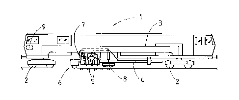
Fig. 1 shows a simplified side view of a tamping
machine comprising a tamping unit for tamping two
immediately adjacent sleepers, and

4 7 ~
Fig. 2 shows an enlarged detailed view of the
tamping unit.
DETAILED DESCRIPTION OF THE PREFERRED EMBODIMENT
The tamping machine 1 is designed to travel
continuously during operation has a machine frame 3
supported on on-track undercarriages 2 and a satellite
frame 4 which is displaceable longitudinally relative to
the machine frame 3. This
.. . .

~l~a~79
. .
satellite frame serves to support a tamping unit 7, designed
to tamp two immediately adjacent sleepers 5 of a track 6, and
a track lifting-lining unit 8. The various drives are
controlled by means of a central control unit 9.
As is shown in Fig. 2, the tamping unit 7 has on either
longitudinal side of the rail two immediately adjacent inner
tamping tools 10,11 and two outer tamping tools 12,13 arranged
on either side thereof - in the longitudinal direction of the
machine or track. Whilst the two inner tamping tools 10,11
and one outer tamping tool 12 are mounted on a common, first
tool carrier 14, the other outer tamping tool 13 is mounted on
a second tool carrier 15. The second tool carrier 15 has a
vibration drive 16 with an eccentric shaft 17, on which a
squeeze drive 18 connected to the outer tamping tool 13 is
rotatably mounted. The second tool carrier 15 is mounted for
displacement on a vertical guide 19 and is vertically
adjustable by means of a vertical adjustment drive 20. The
outer tamping tool 13 mounted on the tool carrier 15 so as to
tilt about an axis 21 extending perpendicularly to the
longitudinal direction of the machine and horizontally is
connected in its lower end region to a tamping tine 22. The
eccentric shaft 17 of the vibration drive 16 is arranged on
the side of the second tool carrier 15 away from the first
tool carrier 14. The guide 19 is located between the axis 21
of the outer tamping tool 13 and the eccentric shaft 17, with
respect to the longitudinal direction of the machine. The
guide 19 of the second tool carrier 15, which is rectangular
in cross-section, and other guides 23 for the vertical
adjustment of the first tool carrier 14 are mounted on a
common auxiliary frame 24 which is connected to the satellite
frame 4 shown in Fig. 1.
The inner tamping tools 10,11 and one outer tamping tool
12 which also have tamping tines 22 and are mounted on the
first tool carrier 14 are connected by way of squeeze drives
25 to an eccentric shaft 26 of another vibration drive 27.
... . .. ...
-

~IS~i~79
The inner tamping tools 10,11 with their squeeze drives 25 are
in this case arranged symmetrically in relation to a vertical
plane of symmetry 29 leading through the axis of rotation 28
of the associated eccentric shaft 26. The fir~t tool carrier
14 is vertically adjustable with the aid of a vertical
adjustment drive 30. The two vertical adjustment drives 20
and 30 may be coupled for joint or synchronous operation with
the aid of the control unit 9.
If both vertical adjustment drives 20 and 30 are operated
synchronously, the two tool carriers 14,15 are then lowered
simultaneously and all the tamping tines 22 are thereby
immersed simultaneously in order to tamp two adjacent sleepers
5 at the same time. Similarly, the lifting of the inner and
outer tamping tools 10 to 13 is performed by synchronous
operation of the two vertical adjustment drives 20,30. As
soon as any obstruction appears in the region of the outer
tamping tool 13 which makes penetration of the associated
tamping tine 22 into the bedding ballast impossible, only the
vertical adjustment drive 30 is operated to lower the first
tool carrier 14, causing only the two tamping tines 22 of the
inner tamping tools 10,11 and the tamping tine 22 of one outer
tamping tool 12 to penetrate into the bedding ballast so as to
tamp it. It is advantageous if the independently vertically
adjustable outer tamping tool 13 is arranged so as to precede
the other tamping tools 10,11,12 in the working direction of
the tamping machine 1.
.. . . .. . . .. ...

Representative Drawing
A single figure which represents the drawing illustrating the invention.
Administrative Status

2024-08-01:As part of the Next Generation Patents (NGP) transition, the Canadian Patents Database (CPD) now contains a more detailed Event History, which replicates the Event Log of our new back-office solution.

Please note that "Inactive:" events refers to events no longer in use in our new back-office solution.

For a clearer understanding of the status of the application/patent presented on this page, the site Disclaimer , as well as the definitions for Patent , Event History , Maintenance Fee  and Payment History  should be consulted.

Event History

Description Date
Time Limit for Reversal Expired 2014-08-05
Letter Sent 2013-08-05
Grant by Issuance 1999-04-20
Inactive: Final fee received 1999-01-20
Pre-grant 1999-01-20
Notice of Allowance is Issued 1998-12-22
Letter Sent 1998-12-22
Inactive: Status info is complete as of Log entry date 1998-12-16
Inactive: Application prosecuted on TS as of Log entry date 1998-12-16
Inactive: Approved for allowance (AFA) 1998-11-27
Application Published (Open to Public Inspection) 1996-02-10
Request for Examination Requirements Determined Compliant 1995-08-29
All Requirements for Examination Determined Compliant 1995-08-29

Abandonment History

There is no abandonment history.

Maintenance Fee

The last payment was received on 1998-07-21

Note : If the full payment has not been received on or before the date indicated, a further fee may be required which may be one of the following

  • the reinstatement fee;
  • the late payment fee; or
  • additional fee to reverse deemed expiry.

Patent fees are adjusted on the 1st of January every year. The amounts above are the current amounts if received by December 31 of the current year.
Please refer to the CIPO Patent Fees web page to see all current fee amounts.

Owners on Record

Note: Records showing the ownership history in alphabetical order.

Current Owners on Record
FRANZ PLASSER BAHNBAUMASCHINEN-INDUSTRIEGESELLSCHAFT M.B.H.
Past Owners on Record
FRIEDRICH PEITL
JOSEF THEURER
Past Owners that do not appear in the "Owners on Record" listing will appear in other documentation within the application.
Documents

To view selected files, please enter reCAPTCHA code :


To view images, click a link in the Document Description column. To download the documents, select one or more checkboxes in the first column and then click the "Download Selected in PDF format (Zip Archive)" or the "Download Selected as Single PDF" button.

List of published and non-published patent-specific documents on the CPD .

If you have any difficulty accessing content, you can call the Client Service Centre at 1-866-997-1936 or send them an e-mail at CIPO Client Service Centre.


Document
Description 
Date
(yyyy-mm-dd) 
Number of pages   Size of Image (KB) 
Abstract 1996-02-09 1 32
Description 1996-02-09 5 221
Claims 1996-02-09 2 65
Drawings 1996-02-09 1 25
Description 1998-11-12 7 281
Claims 1998-11-12 2 78
Representative drawing 1999-04-12 1 5
Commissioner's Notice - Application Found Allowable 1998-12-21 1 163
Maintenance Fee Notice 2013-09-15 1 170
Correspondence 1999-01-19 1 43
Prosecution correspondence 1995-08-03 7 297
Courtesy - Office Letter 1996-02-21 1 59
Examiner Requisition 1998-03-16 2 62
Examiner Requisition 1998-07-30 1 25
Prosecution correspondence 1998-08-16 2 42
Prosecution correspondence 1998-06-28 3 68