Note: Descriptions are shown in the official language in which they were submitted.
21 55490
-1-
This invention relates generally to instruments for
bending sheets of material and relates in particular to a device
for bending sheets of metal for use, for example, in orthopedic
applications (including but not limited to repair of maxillo-
facial fractures).
In the prior art, there has been a need for bent metal
plates for use in repairing fractures, for example facial
fractures. Such repairs of facial fractures can be accomplished
by use of so-called Luhr plates, which are manufactured by
Howmedica Inc.
In bending such plates, it has been known to bend the
plates to fit the particular facial fracture, with one bend
being made, followed by a second bend so as to fit the facial
dimensions of the patient.
However, an improvement was sought for bending such
plates which would have improved accuracy and reduction of the
time for this bending procedure.
The invention provides a tool for bending a facial
bone plate simultaneously at two positions separated by an off-
set length L comprising: a pliers having a first and second
jaw; a first modular bending jaw for attachment to said first
jaw of said pliers; a second modular bending jaw for attachment
to the second jaw of said pliers, said first modular bending
jaw having a first face with a groove therein which engages a
corresponding protrusion on said first pliers' jaw and a second
planar face separated apart from said first face and having a
cross-section having said offset length L which is bounded by a
first plane and a second plane oriented at an angle al and a2
with respect to said second face, said second modular bending
jaw comprising a third face having a groove therein which
engages a corresponding protrusion of said second pliers' jaw
and a fourth face spaced apart from said third face and having
a cross-section having said offset length L which is bounded by
a third plane and a fourth plane oriented at an angle a3 and a4
with respect to said fourth face.
It is desirable to provide a device for bending metal
plates for use in orthopedics which will save time, compared
67044-31
21 55490
-2-
with the bending procedure used in the prior art, i. e. which
will satisfy the two purposes of bending to the desired shape
and of sizing (i. e., measuring the size of offset length
required).
Also according to the invention, in a preferred
embodiment, the bending jaws are substantially identical, and
angle a and angle S are both 90°.
In yet another preferred embodiment, the bending jaws
are attached to the pliers by an attaching means, which in one
embodiment is preferably a spring detent and in another embodi-
ment is preferably a pin.
Further, a kit of a plurality of sets of two identical
bending jaws with offsets equal to a plurality of lengths L,
each set being attachable to a set of pliers is provided. In a
preferred embodiment, the distances are of 1 millimeter
increments, so as to provide, for example, a kit of bending jaws
for use in bending a plurality of metal plates of different off-
set lengths, with a preferred kit comprising ten sets of two
identical bending jaws with offsets equal to 2, 3, ...11 mm.
Description of the Pref erred Embodiments
Brief Description of the Drawings
In Figure 1, a side view (with phantom lines showing
parts obscured from view) of a preferred embodiment of a bending
instrument according to the invention is shown with its jaws in
their open position, showing a set of two substantially identi-
cal bending jaws attached to a pliers.
Figure 2 is a top view of the device of Figure 1.
Figure 3 is a plan view of the part of the device
shown in Figure 1 which is to be connected as shown in Figure 1
to the two basic pliers handles, showing an exploded view of one
bending jaw separated from one pliers jaw and a matching bending
jaw attached to the other pliers jaw.
In Figure 4A, a sheet of metal is shown located
between a set of two matching bending jaws which are in their
open position, each of the two substantially identical matching
bending jaws connected to a different pliers jaw and held in
place by the friction produced by the spring-actuated pressure
of a ball, prior to the event of the bending of the metal sheet.
67044-31
21 55490
-3-
In Figure 4B, the items shown in Figure 4A are shown in the closed position of
the two substantially identical matching bending jaws, during the event of the
bending
of the metal sheet, in which the metal sheet assumes simultaneously a shape
having
two substantially identical angles separated by an offset length, the bent
shape being
achieved by one stroke of the bending pliers according to the invention.
Figure 5 is a top view of a part of the device shown in Figure 2.
Figure 6 is a side view of the lower pliers jaw as shown in Figure 3 (but
without
the bending jaw attached and with the pliers jaw rotated through 90°).
Figures 7A and 7B are side views of an embodiment of two bending jaws of the
invention (as are shown in Figures 3 and 4, but having two different offset
lengths.)
Figures 8A and 8B show the correspondingly sized bends which are formed by
two bending jaws as in Figure 7A and two bending jaws as in Figure 7B,
respectively.
Figure 9 is a side view of a block of metal showing how from that one block of
metal one of eleven different bending jaws according to the invention can be
cut, each
with an offset separated by two bending angles (which in a preferred
embodiment are
substantially identical angles and are right angles).
Detailed Description of the Drawing
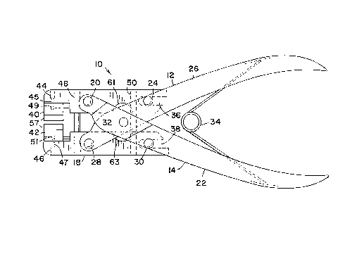
Referring to the drawing, in Figure 1, a side view of an embodiment of the
bending instrument 10 of the invention is shown. That embodiment comprises, in
one
aspect, pliers 12 comprising a basic handle portion 14 (with a second pliers
handle 22
and a first pliers handle 26) and a first pliers jaw 16 and a second pliers
jaw 18. The
first pliers jaw 16 is pivotally connected at first pin 20 to second pliers
handle 22 and
is slidably connected at second pin 24 to first pliers handle 26. Likewise,
second pliers
jaw 18 is pivotally connected at third pin 28 to first pliers handle 26 and is
also
simultaneously slidably connected at fourth pin 30 to second pliers handle 22.
First
pliers handle 26 and second pliers handle 22 are pivotally connected together
at rivets
32 and 33. Spring 34 serves to force first pliers handle 26 and second pliers
handle
22 apart and to force first pliers jaw 16 and second pliers jaw 18 together in
the rest
position of spring 34 when it is in its uncompressed state. Second pin 24 can
slide
within slot 36 of first pliers jaw 16, and fourth pin 30 can slide within slot
38 of second
pliers jaw 18.
Also shown in Figure 1 are first bending jaw 40 and second bending jaw 42,
which in this preferred embodiment are a matching pair of substantially
identical
21 55490
bending jaws positioned and held in place on first pliers jaw 16 and second
pliers jaw
18, respectively, by means of screw 44 and screw 46 which are used to secure
springs
45 and 47 and balls 49 and 51 in jaws 16 and 18, respectively. The balls 49
and 51 are
used to bear against the holes 76 and 78 in jaws 40 and 42 to keep jaws 40 and
42 in
place on the pliers jaws 16 and 18, respectively. See also Figures 4A and 4B,
described below.
Also shown in Figure 1 in phantom lines is first elongated pin 48 and second
elongated pin 50, which serve to stabilize jaws 16 and 18 to assure parallel
movement
of the jaws 16 and 18.
Figure 2 is a top view of the embodiment of the device of the invention shown
in Figure 1, with corresponding parts labeled correspondingly.
In Figure 3, first bending jaw 40 is shown in an exploded view separated from
first pliers jaw 16, whereas second bending jaw 42 is shown in its position
attached to
second pliers jaw 18 (attached by means of pin 46, shown in Figure 1 but not
in Figure
3).
First bending jaw 40 and second bending jaw 42 both have the same first angle
52 and the same second angle 54, which are substantially equal. Additionally,
both first
bending jaw 40 and second bending jaw 42 have the same offset length L 56,
which
is the distance between the vertex 58 of first angle 52 and the vertex 60 of
second
angle 54.
First bending jaw 40 has a slot (or groove or keyway) 62 located within its
planar
face 64, the planar face 64 being spaced apart from the offset length L 56
(which is
angled with respect to planar face 64); and second bending jaw 42 has a slot
(or
groove or keyway) 66 located within its planar face 68, the planar face 68
being spaced
apart from the plane in which offset 56 in second bending jaw 42 is located.
Slot 62
in first bending jaw 40 is shaped slightly larger than but is substantially
identical to the
mating shape 70 of first pliers jaw 16; and, likewise, slot 66 in second
bending jaw 42
is shaped substantially identical to the shape of mating shape 72 in second
pliers jaw
18. In a preferred embodiment, first mating shape 70 and second mating shape
72 are
T-shaped and are an integral part of first pliers jaw 16 and second pliers jaw
18,
respectively.
In Figure 4A, unbent metal sheet 74 is shown positioned between first bending
jaw 40 and second bending jaw 42 when those two bending jaw are in their open
21 55490
-5-
position. First bending jaw 40 is connected to first pliers jaw 16 by means of
first jaw
screw 44, which bears against a compression spring 45 which bears against a
ball 49
which bears against the hole 76 with sufficient friction to prevent
disassociation of the
jaw 40 from the pliers jaw 16.
In Figure 4B, the same items shown in Figure 4A are shown, but with the mating
first bending jaw 40 and second bending jaw 42 being shown in the closed
position
such that the metal sheet is bent at two places simultaneously with the same
bent
angle.
Figure 5 is a view from above of the first pliers jaw 16 shown in Figures 1
and
3, without having attached thereto first bending jaw 40. Figure 5 is also a
top view of
a part of the device shown in Figure 2.
Figure 6 is a side view taken along the line 6-6 in Figure 3 of second pliers
jaw
18, which also is shown in Figure 1 and taken along the line 6-6 in Figure 1.
Corresponding parts are labeled correspondingly. Grooves 61 and 63 are
required to
prevent the jaws from hitting rivets 32 and 33, respectively.
Figure 7A and 7B are side views of first bending jaw 40 (and also of second
bending jaw 42) but having offset lengths L 56 of two different lengths.
Figures 8A and 8B are cross-sectional views of metal plate 74 (viewed in cross-
section) showing how it would be bent when two substantially identical bending
jaws
as shown in Figure 7A are used according to the invention and when two
substantially
identical bending jaws as shown in Figure 7B are used, respectively, showing
two
differently sized offsets 56 (as are shown in Figure 7A and 7B, respectively).
Figures 8A and 8B show in cross-section two metal sheets which were each
bent by using together two substantially identical bending jaws as shown in
Figures 7A
and 7B, respectively.
Figure 9 is a side view depicting how a single block of metal with eleven
different offsets are cut from that same piece of metal so as to form eleven
different
bending jaws, each having two substantially identical bending angles which are
separated by an offset length which is different for each of the eleven
different bending
jaws. The preferred T-shaped slot (or groove or keyway 62, 66) is also shown
in the
bending jaw 40, 42.
The offset distance 56 in the bending jaws of the invention can be chosen as
desired. However, for use in bending plates of metal for use on facial
fractures,
21 55490
-6-
preferably the offset distance will be chosen for an individual bending jaw
from within
the range from 2 to 11 millimeters. Most preferably, sets of the bending jaws
will be
formed in sets of 10, with offset increments of 1 millimeter and will be 2,
3....11
millimeters.
Preferably first bending jaw 40 and second bending jaw 42 will be attached to
first pliers jaw 16 and second pliers jaw 18, respectively as described above.
However,
any other suitable means of attachment can be used.
Preferably, first angle 52 and second angle 54 will be both right angles
(i.e.,
90°). However, if desired, the angles can be other than 90° and
can be unequal
angles.
The spring of pliers 10 keeps the jaws in an open position when the spring is
not compressed.
Preferably the slot (or groove or keyway) 62 in first bending jaw 40 and the
slot
66 in second bending jaw 42 are T-shaped so that the bending jaw can be slid
onto the
corresponding pliers jaw.
By use of the pins 20, 24, 28, and 30, the jaws of the pliers in a preferred
embodiment move in a parallel manner (that is, the jaw faces remain parallel
to each
other when the handles 22, 26 are squeezed).
Suitable pliers which are commercially available for use with the first
bending jaw
40 and second bending jaw 42 of the invention are available from Aesculap.
The advantages of the bending instrument of the invention include the
following.
The device saves time in bending metal plates. Smaller inventories of bending
jaws
and of bent plates are required because the bent plates can be produced as
needed.
The bending jaws can serve as gauges when templates are used to establish the
offset
distance which is required, and then the plates can be bent with the
appropriate pair
of bending jaws.