Note: Descriptions are shown in the official language in which they were submitted.
CA 02156029 1999-09-24
COMPACT OPTICAL SWITCH
Field of the Invention
This invention relates to optical switching devices and more particularly, to
a fiberoptic
switch for optically connecting an optical fiber, or generally a waveguide,
with one or
more other optical fibers or waveguides.
Background of the Invention
Optical switches which afford an optical connection of a single input
waveguide with a
plurality of output waveguides are known in the art. Devices described in US
patent
4,896,935 and US patent 4,834,488 to Lee operate by rotating the end portions
of certain
fibers to align them optically with other fibers, all the fibers (or at least
their end portions
to be aligned) being positioned in a common plane.
US patent 4,378,144 to Duck et al. proposes an arrangement wherein a faceplate
comprising a number of collimating lenses along a pitch circle is attached
directly to a
stepping motor, the shaft of the motor being coaxial with the pitch circle. A
rotatable arm
2 0 with a collimating lens is attached to the shaft for rotation along the
pitch circle, with a
small distance therebetween, so that the lens of the arm can be optically
connected with
the lenses on the faceplate when the rotatable arm is moved by means of the
shaft of the
stepping motor. An optical input fiber is connected to the collimating lens of
the arm and
a plurality of optical output fibers is attached to the respective collimating
lenses on the
2 5 faceplate for a switching operation when the rotatable arm moves from one
position to
another.
While the device of Duck et al. is useful, it has certain disadvantages. Since
the output
fibers are arranged parallel to the axis of the stepping motor and surround
the motor, and
3 0 since the input fiber is rotated along the pitch circle for alignment with
the output fibers,
the pitch circle must have a diameter at least equal to the diameter of the
stepping motor.
This creates a demand for space as the faceplate has a larger diameter than
the respective
size of the stepping motor, and also increases the possibility of an alignment
error because
of a relatively large radius of the pitch circle.
An attempt to solve the above problems was made in US patent 5,317,659 to Lee.
The
end portions of a number of optical fibers are fixed onto the conical surface
of a supporting
CA 02156029 1999-09-24
frame. The end portion of a movable fiber is rotated about the axis of a
conical surface so
that the end portion of the movable fiber is aligned with one of the fixed
fibers.
While the device of US patent 5,317,659 overcomes the problem of the size of
the
faceplate of Duck ' 144, the device itself is rather difficult to manufacture
and may be prone
to alignment problems.
Summary of the Invention
It is an object of the present invention to provide an optical switching
device which
combines a relatively compact design with a high operational accuracy and
reliability as
well as a relative ease of manufacture.
According to the invention, an optical switching device is provided which has
a light input
side and a light output side and which comprises,
a motor having a shaft,
a plurality of optical fibers on one side of the device, each fiber having a
fixed end
portion, the fixed end portions being located in spaced-apart predetermined
positions
substantially parallel to the axis of the shaft thus defining a substantially
cylindrical
2 0 imaginary surface the diameter of which defines a pitch circle,
an optical fiber on the other side of the device, the fiber having a movable
end
portion,
a means associated with the motor for moving the movable end portion of the
optical
fiber around an arc of the pitch circle so as to reach optically connecting
positions with
2 5 respective fixed end portions of the optical fibers,
35
wherein the diameter of the pitch circle is smaller than the size of the
stepping motor
in a plane perpendicular to its shaft and the fixed end portions are axially
spaced from the
motor by a distance related to the minimum acceptable bending radius of the
optical fibers
on the one side of the device.
The minimum acceptable bending radius of the fibers on the one side of the
device is a
bending radius at which said optical fibers on the one side can bend without
the risk of
breaking, while not causing significant attenuation o light signal in the
respective fibers,
to diverge from their fixed portions and bypass the stepping motor.
Preferably, the end portions of the fibers have gradient index (GRIN) lenses
which are
connected to the end portions to collimate light passing from or to the
respective fibers.
2
CA 02156029 1999-09-24
In a preferable embodiment of the invention, the radius of rotation of the
movable end
portion is different than the radius of the pitch circle of the fixed end
portions whereby the
axes of the corresponding lenses are offset, the difference being selected to
minimize a
reflection of the light signal from the GRIN lens on the output fiber while
enabling
effective light transmission between the input and the output fiber.
Brief Description of the Drawings
The invention will now be explained and described in more detail in
conjunction with
accompanying drawings in which:
Fig. 1 is a perspective view of an embodiment of the switching device of the
invention,
Fig. 2 is a schematic side view of the switching device,
Fig. 3 is a perspective exploded view of the device, and
Fig. 4 is a schematic cross-sectional view illustrating fiber-to-fiber
arrangement in the
2 0 device of the invention using a pair of gradient index (GRIN) lenses.
Detailed Description of the Invention
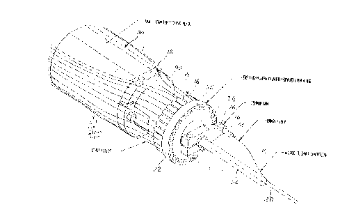
As shown in the drawings, an optical switching device has a light input side
on which it
2 5 comprises a single input optical fiber 10 which has an end portion 12
mounted in a fiber
tube 14. On its light output side, the device has a number of output optical
fibers 18. The
device comprises a small-diameter stepping motor 20 which is attached to a
faceplate 22
such that rotatable shaft 24 of the stepping motor 20 extends through the
fixed faceplate.
An arm 26 is secured to the shaft for rotation about the axis 28 of the shaft
24. The end
3 0 portion 12 of the input fiber 10 is mounted to the arm 26 by means of a
fiber tube 14 and
terminates in a collimating gradient index (GRIN) lens 32, shown in Fig 4
(known under a
trademark SELFOC of Nippon Sheet Glass). The output optical fibers 18 are
attached, in
their end portions 19, to the faceplate 22 through a corresponding number of
fiber tubes 16
attached to collimating GRIN lenses 38 which are mounted in holes 34 uniformly
spaced
3 5 along a pitch circle on the face 36 of the faceplate 22 as illustrated in
Fig. 4.
The axes of the holes 34, defining the pitch circle, and the axis of a hole
(accommodating
the fiber tube 14) in the arm 26 are parallel to the axis 28 of the shaft 24
which facilitates
3
CA 02156029 1999-09-24
the manufacture of the precision bores and the alignment of the input fiber 10
with output
fibers 18. The axis of the hole in the arm 26 may be offset relative to the
pitch circle as
explained hereinbelow in conjunction with Fig. 4.
It is seen from Figs. 1 and 2 that the diameter of the pitch circle defined by
the axes of the
holes 34 is smaller than the diameter, or average cross-sectional size D, of
the stepping
motor 20 as measured perpendicularly to the axis 28. This difference in the
diameters
should be such that the external diameter of the faceplate 22 with its
mounting 40 does not
exceed the diameter, or average cross-sectional size D, of the stepping motor
20, or in
other words, that the profile of the faceplate with the moving arm does not
extend beyond
the profile of the stepping motor as seen in the axial direction of the shaft.
Further, it is seen from Figs. 1 and 2 that the faceplate 22, in contrast with
the arrangement
of US patent 4,378,144 (Figs. 1, 3 and 4) is axially spaced from the stepping
motor 20 (or
body of the switching device) such as to allow the output optical fibers 18 to
bend gently
to diverge from their end portions towards the stepping motor and to bypass
the motor (or
the body of the device) contiguously with practically no space requirement,
while the
bending radius is large enough to prevent substantial attenuation of optical
signal due to
fiber bending.
Fig. 3 illustrates a stop mechanism of the device of the invention. It is
advantageous to
ensure that in selecting various switching positions of the arm 26, and thus
of the end
portion 12 of the input fiber 10, a rotary motion of the arm is limited to an
arc, preferably
totalling in both directions (clockwise and counterclockwise) 360° but
typically not
2 5 exceeding significantly the full circle.
To this effect, according to the invention, a sensor collar 42 is adapted to
be fixedly
secured to the shaft 24 by means of set screws 44. The collar 42 has a pin, or
flag 46 and
an axial slot 48 on its outside diameter. An axial bore 50 in the sensor
collar has a size
corresponding to the diameter of the shaft 24.
3 0 The sensor collar 42 is adjacent to stop collar 52 which is adapted to be
slidably mounted
on the shaft 24. The stop collar 52 has a pin 54 which extends on both sides
of the collar
52 parallel to the axis 28 of the shaft 24 and is disposed such as to engage
with its one side
the slot 48. The width of the slot 48 is sufficiently larger than the diameter
of the pin 54 to
enable the pin to move within the slot during the rotation of the shaft.
3 5 The purpose of this arrangement is to allow a rotational movement of the
shaft by 360° so
as to enable optical connections along the entire pitch circle.
CA 02156029 1999-09-24
The stop collar 52, guided and positioned by the motor shaft, is dimensioned
to be slidably
and rotatably received in an axial bore 55 of the faceplate 22 which is
adapted to be
fixedly attached to the stepping motor by means of bolts 56 (only one is
shown).
Mounted in the body of the faceplate are an optical sensor 58 which is a shaft
position
indicator, and a pin 60 which extends radially into the axial bore 55 and, in
operation,
engages the pin 54 of the stop collar 52 on the side opposite to that of the
pin 46. Sensor
58 may also be a magnetic or electrical sensor.
In operation, when a control unit (not shown) is given a signal corresponding
to a
particular switching position, the unit generates a number of electrical
pulses to the
stepping motor to reach that switching position. The rotation of the shaft 24
causes the
sensor collar to rotate. Consequently, the stop collar 52 rotates as well up
to a point when
the pin 60 engages and stops the pin 54. This will not stop immediately the
sensor collar
because of some leeway for the pin 54 created by the size of the slot 48 in
the sensor
collar. The situation is reversed when the shaft rotates in the opposite
direction. As a
result, the combined arc travelled by the shaft and the arm 26 attached to it
is at least 360°,
making it possible to use the entire circumference of the faceplate for
optical connections
and easing the accuracy restriction on the end-of travel sensing.
Fig. 4 illustrates the optical connection arrangement preferably used in the
present
invention. The signal light path is indicated with a solid line with arrows
and the reflected
light is shown with dotted lines. In a switching position, two GRIN lenses 32
and 38,
corresponding to the input fiber and to an output fiber respectively, are
arranged so that an
2 5 axial spacing S and a radial spacing L are maintained therebetween. The
fibers 10, 18 are
connected to their respective lenses in an off center manner. The amount of
the offset is
selected to force light to travel through the lenses at an angle, and thus
minimize or reduce
the possibility of backreflection of the light entering the GRIN lens 38
either from the
glass/air interfaces 62, 64, or from the glass/glass interface 66 back to the
input fiber 10.
3 0 The radial spacing L and the spacing S between the GRIN lenses are also
selected with the
same purpose. As seen in Fig. 4, because of the graded index of refraction and
off center
connection of the fibers to the lenses, light passes through the input GRIN
lens 32 and
enters the opposite GRIN lens 38 at an angle. This results in the reflected
portion of light,
indicated by reference numeral 65, being largely redirected away from the face
of the input
3 5 GRIN lens 32.
It is an advantage of the invention to provide an optical switching device
with a relatively
good alignment control and ease of manufacture, at least equal to that of Duck
US patent
5
CA 02156029 1999-09-24
' 144, while offering a space saving comparable to that of Lee US patent '659.
The parallel
arrangement of the fixed end portions of the output fibers is preferable over
a conical
arrangement at least for the manufacturing reasons.
It will be appreciated that the designation of input and output side in the
embodiment
described is exemplary only. The path of light can be reversed so that light
travels from
the plurality of fibers selectively to the single fiber (or a number of
fibers) on the opposite
side.
Various modifications can be made to the above exemplary embodiments without
departing from the scope of the invention which is to be defined only by the
appended
claims.
6