Note: Descriptions are shown in the official language in which they were submitted.
2l~5~l~9
l\~ULTI-MODE WELL TOOL WlIH
HYDRAULIC BYPASS ASSEMBLY
BACKGROUND OF THE INVENTION
1. Field of the Invention
The present invention relates to multi-mode testing tools which are operable in several modes
such as a drill-pipe tester, formation tester, circulation valve and displacement valve.
2. Desclil,lion of the R~l~te~l Art
In oil and gas wells, it is common to conduct well testing and stim~ tion operations to
determine production potential and enh~n- e that potential. Annulus plc~S~ul'e responsive downhole
tools have been developed which operate responsive to pl~s~ul`e changes in the annulus between the
testing string and the well bore casing and can sample formation fluids for testing or circ~ ting
fluids thelc~ ough. These tools typically incorporate both a ball valve and lateral circulation ports.
Both the ball valve and circulation ports are operable between open and closed positions. A tool of
this type is described in U.S. Patent No. 4,633,952 issued to Ringgenberg and assigned to
Halliburton Colllpally. A commercially available multi-mode testing tool of this type is the Omni
SandGuard IV Circ~ ting Valve. The tool is capable of performing in different modes of operation
as a drill pipe tester valve, a circulation valve and a formation tester valve, as well as providing its
operator with the ability to displace fluids in the pipe string above the tool with nitrogen or another
gas prior to testing or retesting. A popular method of employing the Omni is to dispose it within
a well bore and m~int~in it in a well test position during flow periods with the ball valve open and
the circulation ports closed. At the conclusion of the flow periods, the tool is moved to a circulating
position with the ports open and the valve closed. The tool is operated by a ball and slot type
ratchet mech~ni~m which provides opening and closing of the valve responsive to a series of ~nmlhl~
pressure increases and decreases. Unfortunately, the ch~nging between tool modes in the present
tool is limited in that the ratchet dictates preprogrammed steps for c~nging the tool between its
~l~g~2~
different positions. An operator must follow each of the preprogrammed steps to move the tool
between positions. A standard Omni ratchet, for in~t~nre, requires 15 cycles of pres~uli~alion and
depres~uliG~Lion in the annulus to move the tool out of the well test position, into the circ~ ting
position and back again. This process requires approximately one hour.
It would be desirable, therefore, to employ a tool which will allow an operator to shift the
tool from a well test position to a circ~ ting position with a minimum of plCS~iUlc cycles. An
operator would be able to m~int~in his tool in the well test position and close the tool when desired
without following a preprogrammed cycle schedule. The number and times of closures could be
orchestrated in accordance with programs established by reservoir engineers or supervisors.
SUMMARY OF THE INVENTION
An improved annulus plCS~ulc responsive tool is described of the type which contains lateral
circulation ports and a ball valve, each of which are operable between open and closed positions to
configure the tool into dirrelcn~ modes of operation. These modes include a well test position in
which the ball valve is open and the circulation ports are closed, a blank position in which the ball
valve and circulation ports are both closed, and a circlll~ting position in which the ball valve is
closed and the circulation ports are open. Through manipulation of annulus pressure, the tool mode
can be changed upon reduction or release of annulus plC~ UlC to move the tool out of the well test
position and into the blank and circulating positions.
An operating mandrel assembly is slidably disposed within the exterior housing of the tool
whose movement dictates the positions of both the circulation ports and the ball valve. The
operating mandrel is moveable by means of an annulus pfes~ulc con~ cting channel which is capable
of receiving, storing and releasing annulus p~CS~ulc increases. A ratchet assembly associates the
- ~15~ 2~
operating mandrel assembly and housing and functions as an overrideable position controller which
dictates response and movement of the operating mandrel assembly to annulus pressure changes.
The ratchet assembly contains a pair of ratchet balls which travel in ratchet slots on a ratchet slot
sleeve. The ratchet slots feature a well test travel path within which the ratchet balls are m~int~in~d
during normal operation of the tool in its well test position. A secondary ratchet path is contiguous
to the well test path. The ratchet balls may be redirected into the secondary ratchet path and moved
to ratchet ball positions which permit the operating mandrel assembly to be moved to positions
corresponding to blank and circ~ ting modes for the tool.
A fluid metering assembly is featured which includes upward and dowllw~ld fluid paths for
flow during annulus pressure changes. The upward flow path towards the fluid spring during
annulus ples~uli~alion permits relatively unrestricted fluid flow. The dowllw~ld flow path away
from the fluid spring during a release of annulus pressure provides metered flow to provide an
operator sufficient time to generate an annulus plCSsulc increase to move the ratchet balls out of the
well test travel path and into the secondary path.
A hydraulic bypass assembly is included which selectively reduces the time required for
portions of the metered tr~n~mi~ion of stored fluid plcs~ure away from the fluid spring. The bypass
assembly includes a bypass mandrel and associated fluid collllllullication bypass grooves which
increase the flow of fluid away from the fluid spring and toward the ratchet assembly during portions
of the pressure release operation.
BRIEF DESCRIPTION OF THE DRAWINGS
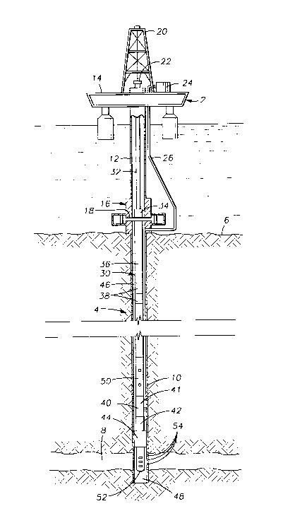
FIGURE 1 provides a schematic vertical section view of a representative offshore well with
a platform from which testing may be con-1~lctrd and illustrates a formation testing string or tool
2 1 ~
assembly in a submerged well bore at the lower end of a string of drill pipe which extends upward
to the platform.
FIGURES 2A-2J are a vertical half section of an exemplary tool of the present invention in
a well test mode.
FIGURES 3A-3J are a vertical half-section of the tool of FIG. 2 in a blank mode.
FIGURES 4A-4J are a vertical half-section of the tool of FIG. 2 in a fluid circulation mode.
FIGURE 5 illustrates a plefell~d slot design for a tool constructed in accordance with the
present invention.
DETAILED DESCRIPTION OF PREFERRED EMBODIMENTS
Referring to FIG. 1, the present invention is shown sch~m~tic~lly incorporated in a testing
string deployed in an offshore oil or gas well. Platform 2 is shown positioned over a submerged
oil or gas well bore 4 located in the sea floor 6, well bore 4 penetrating potential producing
formation 8. Well bore 4 is shown to be lined with steel casing 10, which is cemented into place.
A subsea conduit or riser 12 extends from the deck 14 of platform 2 to a subsea wellhead 16, which
includes a blowout preventer 18. Platform 2 supports a derrick 20 thereon, as well as a hoisting
appal~us 22, and a pump 24 which commlmic~Ps with the well bore 4 via control conduit 26,
which extends to ~nnl~ 46 below blowout preventer 18.
A testing string 30 is shown disposed in well bore 4, with blowout plevellLel 18 closed
thereabout. Testing string 30 includes an upper drill pipe string 32 which extends dowllw~ld from
platform 2 to wellhead 16, whereat is located a hydraulically operated "test tree" 34, below which
extends intermP~ te pipe string 36. Slip joint 38 may be included in string 36 to compensate for
vertical motion imparted to platform 2 by wave action; slip joint 38 may be similar to that disclosed
156i2~
in U.S. Patent No. 3,354,950 to Hyde. Below slip joint 38, intermediate string 36 extends
downwardly to a multi-mode testing tool 50 of the present invention. Below multi-mode tool 50 is
a lower pipe string 40, exten~ling to a tubing seal assembly 42, which stabs into a packer 44. Above
the tubing seal assembly 42 on the lower pipe string 40 is a tester valve 41 which may be of any
suitable type known in the art. When set, packer 44 isolates upper well bore annulus 46 from lower
well bore 48. Packer 44 may be any suitable packer well known in the art, such as, for example,
a Baker Oil Tool Model D packer, an Otis Fngin,oering Corporation Type W packer, or Halliburton
Services CHAMP~, RTTS, or EZDRILL~ SV packers. Tubing seal assembly 42 permits testing
string 30 to c~"-",~ ic~te with lower well bore 48 through a perforated tail pipe 52. In this manner,
formation fluids from formation 8 may enter lower well bore 48 through the perforations 54 in
casing 10, and flow into testing string 30.
After packer 44 is set in well bore 4, a formation test for testing the production potential of
formation 8 may be con~ cte~l by controlling the flow of fluid from formation 8 through testing
string 30 using variations in pressure to operate tool 50. The pressure variations are effected in
upper ~nmlllls 46 by pump 24 and control conduit 26, lltili7ing associated relief valves (not shown).
Prior to the actual test, however, the plc~ule integrity of testing string 30 may be tested with the
valve ball of the multi-mode tool 50 closed in the tool's drill pipe tester mode. Tool 50 may be run
into well bore 4 in its drill pipe tester mode, or it may be run in its circulation valve mode to
autom~tir~lly fill with fluid, and be cycled to its drill pipe mode thereafter. As the ball valve in tool
50 of the present invention is opened and closed in its formation tester valve mode, formation
pressure, temperature, and recovery time may be measured during the flow test through the use of
instruments incorporated in testing string 30 as known in the art. Such instruments are well known
` ~lS~12~
in the art, and include both Bourdon tube-type mechanical gauges, electronic memory gauges, and
sensors run on wireline from platform 2 inside testing string 30 prior to the test. If the formation
to be tested is suspected to be weak and easily damageable by the hydrostatic head of fluid in testing
string 30, tool 50 may be cycled to its displacement mode and nitrogen or other inert gas under
plCS~ulc employed to displace fluids from the string prior to testing or retesting.
It may also be desirable to treat the formation 8 in conjul~;Lion with the testing program while
testing string 30 is in place. Treatment programs may include hydraulically fracturing the formation
or acidizing the formation. Such a treatment program is con~ cte~l by pumping various chr-mir~l~
and other materials down the flow bore of testing string 30 at a pressure sufficient to force the
chemicals and other materials into the formation. The chemicals, materials, and pressures employed
will vary depending on the formation characteristics and the desired changes thought to be effective
in enhancing formation productivity. In this manner, it is possible to conduct a testing program to
determine treatment effectiveness without removal of testing string 30. If desired, treating chemicals
may be spotted into testing string 30 from the surface by placing tool 50 in its circulation valve
mode, and displacing string fluids into the annulus prior to opening the valve ball in tool 50.
At the end of the testing and treating programs, the circulation valve mode of tool 50 is
employed, the circulation valve opened, and formation fluids, chemicals and other injected materials
in testing string 30 circulated from the interior of testing string 30 are pumped back up the testing
string 30 using a clean fluid. Packer 44 is then released (or tubing seal 42 withdrawn if packer 44
is to remain in place) and testing string 30 withdrawn from well bore 4.
FIGS. 2A-2J illustrate a well tool 50 which is similar in some respects to that described in
United States Patent No. 4,633,952 issued to Ringgenbelg and assigned to the assignee of the present
1 2 g
invention and which is incorporated herein by reference. Tool 50 is shown in section, enclosing a
central flow conducting passage 56. As may be appreciated by reference to the drawings,
connections of components are often complimented by the use of O-rings or other conventional seals.
The use of such seals is well known in the art and, therefore, will not be ~ c~ ecl in detail.
Commencing at the top of the tool 50, upper adapter 100 has threads 102 therein at its upper end,
whereby tool 50 is secured to drill pipe in the testing string 30. Upper adapter 100 is secured to
nitrogen valve housing 104 at threaded connection 106. Housing 104 contains a valve assembly (not
shown), such as is well known in the art, and a lateral bore 108 in the wall thereof, co-l---,-lnir~ting
with dowl-waldly extending lon~it~ in~l nitrogen charging channel 110.
Valve housing 104 is secured by threaded connection 112 at its outer lower end to tubular
pressure case 114, and by threaded connection 116 at its inner lower end to gas chamber mandrel
118. Case 114 and mandrel 118 define a pl~s~ufi;~ed gas chamber 120 and an upper oil chamber
122, the two being s~al~t~d by a floating annular piston 124. Channel 110 is in co---",~ tion
with chamber 120.
The upper end of oil channel coupling 126 extends between case 114 and gas chamber
mandrel 118, and is secured to the lower end of case 114 at threaded connection 128. A plurality
of longit~ in~l oil channels 130 spaced around the circumference of coupling 126 (one shown),
extend from the upper terminal end of coupling 126 to the lower terminal end thereof. Radially
drilled oil fill ports 132 extend from the exterior of tool 50, intersecting with channels 130 and
closed with plugs 134. The lower end of coupling 126, includes a dowllwdldly facing lower side
127 and is secured at threaded connection 140 to the upper end of connector housing 123.
21~612~
Connector housing 123 is conn~cted at its lower portion by threaded connection 125 to the
fluid metering assembly 142 which is constructed primarily of upper and lower fluid flow housings
144 and 146 and a metering nut 148. While an exemplary construction for the fluid metering
assembly 142 is described herein, it is understood that other constructions which perform these
functions may also be used.
The upper fluid flow housing 144 is connected at its lower portion by threaded connection
154 to the lower fluid flow housing 146 which is, in turn, conntocted at thread 156 to ratchet case
158, with oil fill ports 160 extending through the wall of case 158 and closed by plugs 162. Ratchet
case 158 presents an inwardly projecting, upwardly facing annular shoulder 164 (see FIG. 2D) on
its inner surface which forms and sepaldles an upper expanded bore 166 from a lower reduced
li~ml-ter bore 168 below. The expanded bore 166 defines a ratchet chamber 170.
Referring now to FIG. 2C, the lower portion of the metering nut 148 is engaged at threads
190 to the upper fluid flow housing 144. The metering nut 148 includes an upward facing port 192
commlmir~ting with a bore 194 extending dowll~4aldly in nut 148. A fluid restrictor 196 is disposed
within the bore 194. A radially inward facing lateral hole 198 in the metering nut 148 permits fluid
co"""ll"i~tion radially inward between the annular gap 182 and the inner radial separation or
clearance 199 between the metering nut 148 and the bypass mandrel 206. When conn~cted,
metering nut 148 and upper fluid flow housing 144, form an external annular groove 200 having a
V-shaped cross-section. Between the upper portion of the metering nut 148 and the upper fluid flow
housing 148 lies fluid passage 195 which extends b~lw~en the groove 200 above and upper annular
gap 182 below. An elastomeric O-ring 202 is seated within the groove 200 so as to block fluid entry
into the groove 200 and between the two pieces, but the O-ring 202 may be urged radially oulwaid
2 ~
by fluid pressure to permit fluid commllnication from the passage 195 uu~w~ld through the groove
200. A radial separation or clearance 204 is present between the metering nut 148 and connector
housing 123.
The lower fluid flow housing 146 includes a pair of longiblAin~l passages 172 which
co"""ul-icates fluid between ratchet chamber 170 below and a lower annular gap 176 above defined
at the connection of upper fluid flow housing 144 and lower fluid flow housing 146.
As depicted in FIG. 2D, on one radial side proximate its bottom portion, upper fluid flow
housing 144 encases an inwardly opening non-annular cavity 178 and an adjoining annular chamber
179. The upper fluid flow housing 144 also encases a first passage 180 which runs between an
upper annular gap 182 formed between metering nut 148 and upper fluid flow housing 144 and the
non-annular cavity 178 below. A plug 184 is disposed within the first passage 180 just below the
upper annular gap 182 so as to block fluid flow thelelhl-~ugh. A radially uulw~ld facing port 186
within the upper fluid flow housing 144 permits fluid c~""lllllnic~tion between the first passage 180
and the radial clearance 204. A second passage 188 also co~""l~l-irates fluid between the lower
annular gap 176 and upper annular gap 182 above.
A bypass mandrel 206 (FIGS. 2B-2C) is disposed within oil channel coupling 126, connector
housing 123, and fluid mPtering assembly 142. A fluid chamber 129 is formed between mandrel
206 and housing 123 with coupling 126 at its upper end and metering assembly 142 at its lower end.
One or more upper bypass grooves 208 are cut into the outer surface of bypass mandrel 206 such
that, when the bypass mandrel is in its lower position fluid may be co"""llnicat~d along grooves 208
between fluid chamber 129 and lateral hole 198.
2 l~ 612~
The fluid metering assembly 142 presents an upper end 150 and lower end 152. The fluid
metering assembly 142 includes an upward flow path and a dowllw~ld flow path for co~ ir-~tion
therebetween. The fluid metering assembly 142 is shown partially in full section in FIGS. 2C-2D
to better demonstrate the upward and dowllwdrd flow paths. In operation, the fluid metering
assembly 142 permits relatively unrestricted upward movement of fluid through upward flow path
188, but will meter fluid duwllward over a period of time through the dowllwar~ flow path.
When an upward plCS~ulc dirrclclllial exists at the lower end 152 of assembly 142, the fluid
metering assembly 142 provides an upward flow path which collullullicates fluid from the ratchet
chamber 170 to fluid chamber 129 without pleselllillg significant resistance. Traveling along the
upward flow path, fluid enters passages 172 at lower end 152 and is co"""ll~ tecl into the lower
annular gap 176, then upward within the second passage 188 of upper fluid flow housing 144 to
upper annular gap 182. Fluid then enters passage 195 and flows radially outward through the V-
shaped groove 200, through the clearance 204 and into fluid chamber 129. Fluid will displace the
0-ring 202 much more easily than it can pass through fluid restrictor 196, and flow past the 0-ring
202 plcsel~L~ no signifir~nt restriction.
When a dow,-wd,d plCS~ulc dirre,c"~ial exists at upper end 150, the fluid metering assembly
142 provides a dow"wald flow path to co""",ll-ic~te fluid dow"w~d from fluid chamber 129 to
ratchet chamber 170. The dowllwald flow path, unlike the upward path, provides flow resistance.
By way of explaining the dowllwdrd flow path, fluid movement within the metering assembly 142
is described as follows. Fluid first enters the radial clearance 204 ~u~ unding the metering nut 148.
Being blocked from entry into the groove 200 by the O-ring 202, the fluid passes further dow"wa,.l
through the clearance 204 and enters the port 186 to move into and dowl,wd,d through the first
~156l ~
passage 180 to the non-annular cavity 178 and non-annular chamber 179. As the fluid cannot
progress beyond the non-annular gap and chamber 178 and 179, it must instead take an alternate
path in which it passes downwardly through the upwardly facing port 192, bore 194 and fluid
restrictor 196 to enter the upper annular gap 182 where it is tr~n~mitted to the second passage 188
of upper fluid flow housing 144 and dowllwal-l to the lower annular gap 176 and can then move into
ratchet chamber 170 through passages 172.
An annular piston 210 (FIG. 2C) is disposed within the fluid chamber 129 and affixed by
lock rings 212 to bypass mandrel 206 to be axially moveable therewith. Piston 210 includes a
longitu-lin~l bore 211 thel~ ough having upper and lower enlarged ~ mPter portions. An upper
check valve 214 with an upwardly extending dart 216 within its upper end is disposed within the
upper enlarged portion of bore 211. The upper check valve 214 is spring biased into a normally
closed position which blocks upward fluid flow across it through the piston 210 but will permit
downward fluid flow under pressure. Dowllw~ld force upon the dart 216 will open the upper check
valve to permit upward fluid flow theleLll,lJugh. Lower check valve 218 is oppositely disposed from
the upper check valve 214 within the lower enlarged portion of bore 211 of piston 210 and carries
a downwardly extending dart 220 within its lower end. It is spring biased into a normally closed
position against dowll~ald fluid flow, but will permit upward fluid flow under pressure. Upward
force upon the dart 220 will open the lower check valve 218 to downward fluid flow thele~ ough.
The bypass mandrel 206 is axially slidable with respect to the oil channel coupling 126,
housing 123, fluid chamber 129 and the fluid metering assembly 142 between an upper position
proximate the lower end of gas chamber mandrel 118 and a lower position proximate the upper end
of ratchet slot mandrel 222. Ratchet slot mandrel 222 extends upward from within ratchet case 158.
2 ~
The upper exterior 224 of ratchet slot mandrel 222 has a reduced, substantially uniform ~ m~ter,
while the lower exterior 226 has a greater cli~mPter so as to provide sufficient wall thickness for
ratchet slots 228. Ratchet slot mandrel 222 includes an annular member 231 projecting radially
outward and forming a piston seat 230 which faces upwardly and ouLw~rdly at the base of the upper
exterior 224 of mandrel 222. There are preferably two such ratchet slots 228 extending
longitll-lin~lly along the lower exterior of the ratchet slot mandrel 222.
The ratchet slot mandrel 222 is axially slidable within tool 50 between upper and lower
positions as will be described in greater detail shortly. Lower longit~l~lin~l bypass grooves 232 are
cut into the upper exterior 224 of ratchet slot mandrel 222. The grooves 232 should be of sufficient
width to permit fluid flow therealong. The lower bypass grooves 232 generally adjoin the lower
fluid flow housing 144 and should be in such a location and of such a length that when the ratchet
slot mandrel 222 is in its upper positions, the grooves 232 are located alongside the lower fluid flow
housing 146 and no fluid flow occurs along the grooves. As the ratchet slot mandrel 222 is moved
toward its lower positions, the grooves 232 will be moved dowllwald such that fluid co-"",ul-ic~tion
may occur between the annular chamber 179 and the ratchet chamber 170.
A ball sleeve assembly 234 surrounds ratchet slot mandrel 222 and comprises shuttle piston
236, upper sleeve 238, lower sleeve 240 and clamp 242 which connects sleeves 238 and 240.
Shuttle piston 236 is constructed similarly in structure and function to annular piston 210 and
is fixedly ?ltt~(`h~l to or unitarily fashioned with upper sleeve 238. The shuttle piston 236 surrounds
the upper exterior 224 of the ratchet slot mandrel 222 within the ratchet chamber 170. Shuttle piston
236 includes a longib~lin~l bore 237 theleLlllough having upper and lower enlarged diameter
portions. An upper check valve 244 with upwardly extending dart 246 within its upper end is
'2156123
disposed in the upper enlarged portion, and lower check valve 248 with downwardly extending dart
250 within its lower end is disposed within the lower enlarged portion. The lower check valve 248
and dart 250 are shown as angled ou~w~ldly within the shuttle piston 236 such that the dart 250
contacts shoulder 164 when ball sleeve assembly 234 is moved downward within the ratchet case
158.
The lower end 252 of the ratchet slot mandrel 222 is secured at threaded connection 254 to
extension mandrel 256. A radial clearance 258 is present between the radial exterior of lower end
252 and the interior surface of ratchet case 158. The lower end 260 of ratchet case 158 is secured
at threaded connection 262 to extension case 264 which surrounds the extension mandrel 256.
Annular intermediate oil chamber 266 is defined by ratchet case 158 and extension mandrel 256.
The intermediate oil chamber 266 is connPcted by oil channels 268 to lower oil chamber 270.
Annular floating piston 272 slidingly seals the bottom of lower oil chamber 270 and divides it from
the lower well fluid chamber 274 into which pressure ports 282 in the wall of case 264 open.
The general construction and operation of ratchet-type assemblies is well known in the art.
Particular ~f~lcllce is made to U.S. Patent No. 4,557,333 issued to Beck, U.S. Patent No.
4,667,743 issued to Rh,ggellberg et al. and U.S. Patent No. 4,537,258 issued to Beck, all of which
are ~c~ignPd to the ~ nPe of the present invention and which are incorporated herein by ler~ e.
As will be appreciated by the discussion that follows, the tool 50 of the present invention
incorporates a novel ratchet assembly having a dual-path ratchet slot within which a ratchet member
is directed. The plilllal~ path is cyclical and m~int~in~ the tool's components in the well test mode.
The secondary path is contiguous to the first path, and redirection of the ratchet member into the
- 21~12~
second path permits the tool's components to be altered so that the tool may be reconfigured into
alternative modes of operation.
Referring now to Figures 2E and 5, two ratchet balls 276 are found in ball seats 278 located
on diametrically opposite sides of lower sleeve 240 and each project into a ratchet slot 228 of semi-
circular cross-section. The configuration of ratchet slot 228 is shown in FIG. 5. As shown there,
the ratchet slot 228 includes an in.~t~ tion groove 281 which has a depth greater than that of the
ratchet slot 228 to permit the introduction and capture of balls 276 during assembly of the tool 50.
The ratchet slot 228 includes a unique pattern or configuration having a number of ball positions,
a, b, c, dl, d2, el, e2, fi, f2, f3, f4, f5, f6 and f7 which are shown in phantom in FIG. 5. The ball
positions correspond to the general positions for balls 276 along ratchet slot 228 during the various
operations involving ~nm~ s plcs.~u~ ion changes. As the balls 276 follow the pa th of slot 228,
lower sleeve 240 rotates with respect to upper sleeve 238, and axial movement of the ball sleeve
assembly 234 is ~ ll.iuP~l to ratchet slot mandrel 222 by balls 276.
Referring again to Figure 2, the lower end of extension case 264 includes oil fill ports 284
cont~ining closing plugs 286. A nipple 288 is threaded at 290 at its upper end to extension case 264
and at 292 at its lower end to circulation displ~etnPrlt housing 294. The circulation displacement
housing 294 possesses a plurality of ch.;ulllfer~llLially spaced, radially extending circulation ports
296, as well as one or more pressure equalization ports 298, extending through the wall thereof.
A circulation valve sleeve 300 is threaded to the lower end of extension mandrel 256 at threaded
connection 302. Valve apertures 304 extend through the wall of circulation valve sleeve 300 and
are isolated from circulation ports 296 by annular seal 306, which is disposed in seal recess 308
formed by the junction of circulation valve sleeve 300 and a lower operating mandrel 310, the two
21~6i2~
being threaded together at 312. Operating mandrel 310 includes a reduced diameter, downwardly
extending skirt having an exterior annular recess 314.
A collet sleeve 318, having collet fingers 320 at its upper end extending upwardly thel~rlo~
engages the downwardly extending skirt 316 of operating mandrel 310 through the accommodation
of radially, inwardly extending protuberances 322 received by annular recess 314. As is readily
noted in FIGS. 2H-2I, protuberances 322 and the upper portions of collet fingers 320 are confined
between the exterior of mandrel 310 and the interior of circulation-displacement housing 294 thereby
m~int~ining the connection.
Collet sleeve 318 includes coupling 324 at its lower end culllylisillg radially extending flanges
326 and 328, forming an exterior annular recess 330 lheleb~Lw~en. A lower coupling 332 comprises
inwardly extending flanges 334 and 336 forming an interior recess 338 therebetween and two ball
operating arms 338. Couplings 324 and 332 are m~int~in~d in engagement by their location in
annular recess 340 between ball case 342, which is threaded at 344 to circulation-displacement
housing 294, and ball housing 346. Ball housing 346 is of substantially tubular configuration,
having an upper smaller diameter portion 348 and a lower, larger ~ m~ter portion 350. Larger
diameter portion 350 has two windows 352 cut through the wall thereof to accommodate the inward
protrusion of lugs 354 on each of the two ball opeldLing arms 338. Windows 352 extend from
shoulder 356 dowllw~ld to shoulder 358 adjacent threaded connection 360 with ball support 362.
On the exterior of the ball housing 346, two longit-lllin~l channels (location shown by phantom arrow
364) of arcuate cross-section and circumferentially aligned with windows 352, extend from shoulder
366 dowllwald to shoulder 356. Ball opeldLillg arms 338, which are of substantially the same
arcuate cross section as channels 364 and lower portion 350 of ball housing 346, lie in channels 364
21~6129
16
and across windows 352, and are m~int~in~d in place by the interior wall 368 of ball case 342 and
the exterior of portion 350 of ball housing 346.
The interior of ball housing 346 possesses upper annular seat recess 370, within which
annular ball seat 372 is disposed, being biased downwardly against ball 374 by ring spring 376.
Surface 378 of upper seat 372 comprises a metal sealing surface, which provides a sliding seal with
the exterior 380 of valve ball 374.
Valve ball 374 includes a diametrical bore 382 thelelhlough of substantially the same
diameter as bore 384 of ball housing 346. Two lug recesses 386 extend from the exterior 380 of
valve ball 374 to bore 382.
The upper end 388 of ball support 362 extends into ball housing 346, and carries lower ball
recess 390 in which annular lower ball seat 392 is disposed. Lower ball seat 392 possesses arcuate
metal sealing surface 394 which slidingly seals against the exterior 380 of valve ball 374. When ball
housing 346 is made up with ball support 362, upper and lower ball seats 372 and 392 are biased
into sealing engagement with valve ball 374 by spring 376.
Exterior annular shoulder 396 on ball support 362 is contacted by the upper ends 398 of
splines 400 on the exterior of ball case 342, whereby the assembly of ball housing 346, ball
operating arms 338, valve ball 374, ball seats 372 and 392 and spring 376 are m~int~in~l in position
inside of ball case 342. Splines 400 engage splines 402 on the exterior of ball support 362, and,
thus, rotation of the ball support 362 and ball housing 346 within ball case 342 is prevented.
Lower adaptor 404 protrudes at its upper end 406 between ball case 342 and ball support
362, sealing therebetween, when made up with ball support 362 at threaded connection 408. The
2156~2~
lower end of lower adaptor 404 carries on its exterior threads 410 for making up with portions of
a test string below tool 50.
When valve ball 374 is in its open position, as shown in FIG. 2I, a "full open" conducting
passage 56 extends throughout tool 50, providing an unimpeded path for formation fluids and/or for
perforating guns, wireline instrumentation, etc.
It is noted that an exterior housing 414 for the tool 50 is made up of upper adapter 100,
nitrogen valve housing 104, pressure case 114, oil channel coupling 126, connector housing 123,
upper and lower fluid flow housings 144 and 146, ratchet case 158, extension case 264, nipple 288,
circulation displacement housing 294, ball case 342 and lower adaptor 404.
The ratchet slot mandrel 222, extension mandrel 256, circulation valve sleeve 300, operating
mandrel 310 may be thought of as an operating mandrel assembly in~ te~l generally at 412.
An annulus pressure con~ cting channel capable of receiving, storing and releasing ~nn~ s
pressure increases is formed by pressure ports 282, fluid chamber 274, floating piston 272, lower
oil chamber 270, oil channels 268, interme~ te oil chamber 266, ball sleeve assembly 234, ratchet
chamber 170, fluid metering assembly 142, fluid chamber 129,1Ongit~ in~l oil channels 130, upper
oil chamber 122, floating piston 124 and plcs~uliGed gas chamber 120. The pressurized gas
chamber 120 functions as a fluid spring while the other components of the pressure con~ cting
channel serve as a pressure con~lllrting passage to co~-~",l-nie~te fluid pressure changes between the
annulus 46 and the fluid spring.
The circulation valve sleeve 300, valve apertures 304, annular seal 306, circulation
displacement housing 294 and circulation ports 296 may be thought of as a fluid circul~ting assembly
612~
18
416 which may be selectively opened and closed to permit fluid flow between the ~nm-ln~ 46 and
the central flow contlucting passage 56 of the tool 50.
OPERATION OF THE PREFERRED
EMBODIMENT OF THE PRESENT INVENTION
Referring to FIGS. 1-5, operation of the combination tool 50 of the present invention is
described hereafter.
As tool 50 is run into the well in testing string 30, it is normally in its well test mode as
shown in FIG. 2, with ball 374 in its open position and ball bore 382 aligned with tool bore 384.
Circulation ports 296 are mi~lign~cl with circulation valve apertures 304, seal 306 preventing
comllluliication therebetween. With respect to FIG. 5, balls 276 will be proximately in position a
in slot 228 as tool 50 is run into the well bore.
Operation of Tool 50 in the Well Test Position During Changes in Annulus Pressurization
Pressure is increased in annulus 46 by pump 24 via control conduit 26. This increase in
pressure is tr~n~mitt~l through ~l~s~ul~; ports 282 (Fig. 2G) into well fluid ch amber 274, where it
acts upon the lower side of floating piston 272. Piston 272, in turn, acts upon a fluid, such as
silicon oil, in lower chamber 270, which co"""~ tes via oil channels 268 with intermediate oil
chamber 266. Fluid pl'l,ssuie in the intermP(li~te oil chamber 266 flows around the lower end 252
of the ratchet slot mandrel 222 to exert upward fluid pleS~ulc~ upon the shuttle piston 236 which pulls
ball sleeve assembly 234. Balls 276 move along slot 228 to position b. Via the association of the
ratchet slot mandrel 222 and ball sleeve assembly 234, the ratchet slot mandrel 222 and the entire
operating mandrel assembly 412 may be moved upward slightly but not a sufficient amount to affect
either the valve ball 374 or the circ~ ting assembly 416.
21~612~
19
Fluid within ratchet chamber 170 is evacuated upward through the fluid metering assembly
142. By virtue of the upward flow path described above, the fluid is co"""-~nir~t~l into fluid
chamber 129 without ~igni~lr~nt flow restriction. Annular piston 210 and the affixed bypass mandrel
206 are moved axially upward. Fluid above the piston 210 is evacuated upward from the fluid
chamber 129 through longit~ in~l channels 130 into upper oil chamber 122 to urge floating piston
124 upward, thereby ples~uli;Ghlg the gas in chamber 120 to store the pressure increase.
As aMulus plt~S~Ulc~ iS subsequently bled off during depre~uli~Lion, the plt'S.~ nitrogen
in chamber 120 pushes dowllwald against floating piston 124 this pressure is tr~n~mitt~l through
fluid within upper oil chamber 122, channels 130 and fluid chamber 129. AMular piston 210 and
the affixed bypass mandrel 206 are moved axially dowllw~ld. Fluid from chamber 129 is
tran~mitt~l dowllw~ld into the ratchet chamber 170 through the dowllwald flow path of the fluid
metering assembly 142. Ball sleeve assembly 234 is, therefore, biased dowllwardly with ratchet
balls 276 following the paths of slot 228 past position c, where they shoulder at position a.
Dowllwald travel of the ball sleeve assembly 234 is limited by engagement of the shuttle piston 236
on piston seat 230 (FIG. 2D). Again, any dowllwald movement of the ratchet slot mandrel 222 and
the operating mandrel assembly 412 will be slight and not sufficient to close the valve ball 374 or
close the circ~ ting assembly 416. As a result, the ratchet assembly may be thought of as providing
a default position sequence with the well test position cycle 283 wherein the opel~ting mandrel
assembly 412 is maint~in~cl during aMulus pleS~ul~ changes in plilllaly mandrel positions such that
the valve ball 374 and the circulating assembly 416 are not affected.
~1~5123
Operation of Tool 50 within a Well Bore
As tool 50 travels down to the level of the production formation 8 to be tested, at which
position packer 44 is set, floating piston 272 moves upward under hydrostatic pressure, pushing ball
sleeve assembly 234 upward and causing balls 276 to move toward position b. This movement does
not change tool modes or open any valves. Upon tool 50 reaching formation 8, packer 44 is set.
The aforesaid feature is advantageous in that it permits pressuring of the well bore annulus 46 to test
the seal of packer 44 across the well bore 4 without closing valve ball 374. It also permits
independent operation of other annulus pressure responsive tools within testing string 30.
Increases in annulus pressure will move floating piston 272 and ball sleeve assembly 234
further upward, its movement ultimately being restricted by the shouldering out of balls 276 at ball
position b within slot 228. Reduction in annulus ples~ulc will move floating piston 272 and ball
sleeve assembly 234 dowll~drd and cause balls 276 to move dow,lwdl-l proximate ball position c
and nltim~tely back to ball position a. The well annulus pressure may be increased and decreased
as many times as desired without moving the tool 50 out of the well test position, the balls 276
following the described well test position path 283, which is made up of the ball positions a, b and
c and the paths of slot 228 connl-cting them. Effectively, the well test position path 283 affords
default position control for the tool 50 by m~int~ining the tool 50 in its well test position during
regular annulus pressurization cycles.
The tool 50 may be changed out of the well test position by increasing annulus pressure
during the portion of the annulus plCS~ulc reduction sequence when balls 276 are proximate ball
position c. As a result, annulus repressurization during a release of stored fluid pressure from the
plcs~u~ized gas chamber 120 acts to override the default position control being provided for the
21~129
operating mandrel assembly 222 by the well test position path 283. Fluid restriction provided by
passage of fluid through the dowllw~ld flow path in the fluid metering assembly 142 will provide
a sufficiently metered downstroke so that an operator will have time to repressurize the annulus.
It is expected that the time required for the ball sleeve assembly 234 to move fully dowllwald so that
the balls 276 essentially return to ball position a is approximately 10 minlltes; the time required for
the balls 276 to move only to position c is approximately 4 mimltes. It should be apparent to one
skilled in the art that the ratchet slot 228 and well test position path 283 might be altered such that
the balls 276 are directed out of the well test position path 283 by an annulus pressure reduction
which occurs during an increase of stored fluid pressure in the pressurized gas chamber 120.
A bypass mechanism is included in tool 50 which shortens the length of time needed for
selected portions of the metered downstroke to be completed. The bypass mech:lni~m employs the
upper and lower bypass grooves 208 and 232 to selectively permit fluid to bypass portions of the
fluid metering assembly at specific points during the downstroke to shorten the downstroke. As the
annular piston 210 and affixed bypass mandrel 206 are moved downward sufficiently, portions of
the lengths of upper bypass grooves 208 are disposed below the upper end 150 and adjacent the
clearance 199 and lateral hole 198 of fluid metering assembly 142. As shown in FIGS. 3C and 4C,
fluid commllnication occurs between the fluid chamber 129 and the upper annular gap 182. The
bypass assembly thereby permits fluid from the fluid chamber 129 to bypass the fluid restrictor 196
and move into the second passage 188 of the upper fluid flow housing 144 where it may be readily
tr~n~mi~t~cl downward into the ratchet chamber 170. The dowllwal.l flow of fluid is thereby
increased speeding up the duwllw~l-l stroke. By choice of width and length of the upper bypass
grooves 208 as well as the placement upon the bypass mandrel 206, the amount and timing of fluid
bypassing may be controlled.
The lower bypass grooves 232, which are located on the upper exterior 224 of the ratchet
slot mandrel 222, are placed such that, when the mandrel 222 is in an upper position, such as in the
well test position, the grooves 232 are generally adjacent the annular chamber 179 and no fluid flow
occurs therealong. See FIG. 2D. As the mandrel 222 moves dowllw~ld with respect to the housing
414, the lower portion of grooves 232 are moved adjacent the ratchet chamber 170 and fluid
co-,-----..-ir~tion is permittçd between the annular chamber 179 and ratchet chamber 170.
When the well bore ann~ s is repressured to move the tool 50 out of its well test position,
the ball sleeve assembly 234 moves upward and balls 276 are moved along slot 228 from proximate
ball position c to a point above ball position d,. The balls 276 have now been directed out of the
well test position cycle shown at 283 on FIG. S and into a contiguous second rat chet path made up
of the rem~in~ier of slot 281 to permit the operating mandrel assembly 412 to move to alternate
mandrel positions wherein the positions of the valve ball 374 and circulating assembly 416 may be
changed. Upward travel of the ball sleeve assembly 234 is llltim~tely limited as shuttle piston 236
encounters the lower end 152 of the fluid metering assembly 142. Downward force is exerted upon
the dart 246 permitting upward fluid flow past the check valve 244 and a subsequent reduction in
the upward pressure dirrel~lllial upon the ball sleeve assembly 234. As the pressure dirrelcll~ial is
recl~lced, balls 276 are shouldered at ball position d,.
Once the balls 276 have been located at ball position d" further reduction of the annlllll~
pressure shifts the tool 50 into its blank position as illustrated by FIG. 3 with the valve ball 374
being moved to a closed position. The operating mandrel assembly 412 is positioned lower with
21~6~2~
respect to the ball sleeve assembly and housing 414 due to engagement of the balls 276 with the
ratchet slot mandrel 222 at ball position dl. The downward pres~ul~ differential upon ball sleeve
assembly 234 urges it downward along with the operating mandrel assembly 412, collet sleeve 318
and ball operating arms 338 to close valve ball 374 such that its bore 382 is not aligned with the ball
housing bore 384. As is a~al~ from FIG. 3H, however, this downward movement is not
sufficient to align the circulation ports 296 with the valve apertures 304 and permit fluid
co"""u~-ir~tion th~le~lrough. As a result, the circul~ting assembly 416 remains closed.
During a subsequent well annulus pressure increase and decrease cycle, balls 276 are moved
along slot 228 to ball position el. This will have the effect of moving the operating mandrel
assembly 412 further dowllwdld with respect to the exterior housing 414. However, the fluid
circll~ting assembly 416 remains closed. To prevent damage to the valve ball 374 and its
surrounding parts as a result of excessive downward movement of the operating mandrel assembly
412, protuberances 322 may become disengaged from recess 314 as shown in FIG. 4I.
As well ann--ll~ plC~S~U~ iS increased and decreased once more, the balls 276 are moved
from ball position el to position fl causing the tool 50 to be moved into its circul~ting position. In
this position, as shown in FIG.4, the valve ball 374 remains closed and the fluid circ~ ting
assembly 416 is opened by the ~lignm~nt of the circulation ports 296 and valve apertures 304 to
permit fluid co,,,,.luniration between the central flow con(l~lcting passage 56 and the well bore
annulus 46. The tool 50 will remain in the circul~ting position during subsequent annulus p~s~ure
change cycles where the balls 276 are moved sequentially to positions f2, f3, f4, f5, f6 and f7.
By way of further explanation of the mode ch~nging and opeldtillg sequence of tool 50, the
reader should note that the tool only changes mode when balls 276 shoulder at specific positions on
612~
24
slot 228 during cycling of the tool since ratchet operation dictates the position of the operating
mandrel assembly 412 within the housing 414. For example, tool 50 changes mode at positions dl,
fl, f7 and d2-
It is also noted that movement between some ball positions is effected by ~nn~ s pressuredecrease followed by an increase rather than the increase/decrease cycle described above. With
respect to FIG. 5, specifically, movement from f6 to f7, from f7 to e2 and from e2 to d2 is
accomplished this way.
The present invention is described with respect to plcfellcd embodiments, but is not limited
to those described. For example, the ratchet slot 228 design may be altered to feature dirrelclll test
positions. Alternatively, the tool 50 might be programmed to effect modes of operation other than
those disclosed with respect to the plcfellcd embodiments described herein. It will be readily
appalcll~ to one of ol-linaly skill in the art that numerous such modifications may be made to the
invention without departing from the spirit and scope of it as claimed.