Language selection

Search

Patent 2156199 Summary

Third-party information liability

Some of the information on this Web page has been provided by external sources. The Government of Canada is not responsible for the accuracy, reliability or currency of the information supplied by external sources. Users wishing to rely upon this information should consult directly with the source of the information. Content provided by external sources is not subject to official languages, privacy and accessibility requirements.

Claims and Abstract availability

Any discrepancies in the text and image of the Claims and Abstract are due to differing posting times. Text of the Claims and Abstract are posted:

  • At the time the application is open to public inspection;
  • At the time of issue of the patent (grant).
(12) Patent: (11) CA 2156199
(54) English Title: ABRASIVE SHEETS
(54) French Title: FEUILLES ABRASIVES
Status: Term Expired - Post Grant Beyond Limit
Bibliographic Data
(51) International Patent Classification (IPC):
  • B24D 11/00 (2006.01)
  • B24B 23/04 (2006.01)
(72) Inventors :
  • MARTIN, MICHAEL (United Kingdom)
  • PUGH, COLIN (United Kingdom)
  • COCKBURN, ERIC (United Kingdom)
(73) Owners :
  • BLACK & DECKER INC.
(71) Applicants :
  • BLACK & DECKER INC. (United States of America)
(74) Agent: MARKS & CLERK
(74) Associate agent:
(45) Issued: 2001-11-27
(22) Filed Date: 1995-08-16
(41) Open to Public Inspection: 1996-02-26
Examination requested: 1998-07-31
Availability of licence: N/A
Dedicated to the Public: N/A
(25) Language of filing: English

Patent Cooperation Treaty (PCT): No

(30) Application Priority Data:
Application No. Country/Territory Date
9417272.3 (United Kingdom) 1994-08-25

Abstracts

English Abstract


An abrasive sheet 1 for a sanding or polishing machine,
comprising a body portion 3 and a tip portion 5 providing a
working point 11, the tip portion 5 being defined by a
weakened region 7 between the body portion 3 and the tip
portion 5, wherein the tip portion 5 can be separated from
the body portion 3, turned through an angle (Figure 2) and
re-positioned adjacent the body portion 3 to change the
working point 11. As a result, an iron-shaped abrasive
sheet, for example, can be provided with a plurality of
working points 11. The sheet can, therefore, be used for
longer periods before it is worn out.


French Abstract

Feuille abrasive 1 pour sableuse ou polisseuse, comprenant une portion de corps 3 et une portion de pointe 5 formant un point de travail 11, la portion de pointe 5 étant définie par une région de faiblesse 7 entre la portion de corps 3 et la portion de pointe 5, la portion de pointe 5 pouvant être séparée de la portion de corps 3, tournée selon un certain angle (figure 2) et repositionnée adjacente à la portion de corps 3 pour changer la pointe de travail 11. Par suite, une feuille abrasive en forme de semelle de fer à repasser, par exemple, peut être munie d’une pluralité de points de travail 11. La feuille peut donc être utilisée pendant des périodes prolongées avant d’être usée.

Claims

Note: Claims are shown in the official language in which they were submitted.

CLAIMS
1 An abrasive sheet for a sanding or polishing machine,
comprising a body portion and a tip portion providing a
working point, the tip portion being defined by a weakened
region between the body portion and the tip portion, wherein
the tip portion can be separated from the body portion,
turned through an angle and re-positioned adjacent the body
portion to change the working point.
2 An abrasive sheet as claimed in claim 1, wherein the
weakened region comprises a line of perforations.
3 An abrasive sheet as claimed in claim 1 or claim 2,
wherein the tip portion includes four working points.
4 An abrasive sheet as claimed in claim 3, wherein the
tip portion is substantially square.
An abrasive sheet as claimed in any preceding claim,
wherein the tip portion has sides which, when the tip
portion is in position adjacent the body portion, complement
the sides of the body portion to produce an iron-shaped
sheet.
6 An abrasive sheet as claimed in any preceding claim,
wherein apertures are provided in the sheet through which
dust and debris can be removed by a sanding machine, during
use.
7 An abrasive sheet as claimed in any preceding claim,
wherein means are provided on one side of the sheet for
attaching the sheet to a sanding or polishing machine.
6

8. An abrasive sheet as claimed in claim 7, wherein the
attachment means are hooks or eyes of a VELCRO-type fastening system.

Description

Note: Descriptions are shown in the official language in which they were submitted.


r~ ` 2I~6199
16823
ABRASIVE ~n~
This invention relates to abrasive sheets, such as
sandpaper, glass paper or any sheet material used for
5 sanding or polishing.
Hand-held electric sanders are well known. Many such
sanders are designed to carry rectangular sand paper sheets
of quarter size, third size or half size, more usually third
10 size sheets. Although such sanders have been very popular,
they have not always enabled a user to sand in tight
corners, for example. Hence, sanders have been designed to
accommodate triangular sheets of sand paper or sheets of
sand paper having a shape similar to an iron base. Both of
15 these sheet shapes enable the user of a sander to reach into
tight corners of a workpiece to achieve complete sanding of
the workpiece.
By providing a sand paper sheet which is triangular,
20 the sheet is effectively provided with three different tips.
Hence, since it is usually the tip of a sand paper sheet
which wears out first, a triangular sand paper sheet can be
made to last up to three times as long as a sheet with only
one tip simply by removing the sheet from the base of the
25 sander, rotating the sheet through 120 and replacing the
sheet on the sander base. This can, of course, be done
twice before the three tips of the sand paper sheet are worn
out.
In contrast to a triangular sand paper sheet, the
iron--shaped sand paper sheet has only tip for use in tight
corners of a workpiece. The sheet does, however, in general
have a greater surface area than a triangular sheet which
can be useful when a significant amount of plane sanding is
35 also required. Further, the rounded edges of the

21~6199
16823
iron-shaped sheet in the regions approaching the tip of the
sheet enable the sander to work up close to a surface
perpendicular to the work surface being sanded by the
sander, by virtue of the sander "rolling" along the
5 perpendicular surface.
In view of the foregoing, the present invention aims to
improve upon the known prior art iron-shaped sanding sheets
by providing a sheet having a plurality of tips.
According to the present invention, there is provided
an abrasive sheet for a sanding or polishing machine,
comprising a body portion and a tip portion providing a
working point, the tip portion being defined by a weakened
15 region between the body portion and the tip portion, wherein
the tip portion can be separated from the body portion,
turned through an angle and re-positioned adjacent the body
portion to change the working point.
By virtue of the removable tip portion, a complete
sanding sheet having an iron-shape, for example, can be
manufactured from a single sheet, and yet the sheet can
still have more than one working point to enable the sheet
to last longer, during use.
The weakened region may comprise a line of
perforations. Alternatively, a score line may be drawn on
the sheet, during manufacture, to define the weakened
region. Other ways of producing a weakened region may, of
30 course, alternatively be used.
The tip portion preferably includes four working
points. As a result of this, an abrasive sheet according to
the present invention has a third more working points than a
35 prior art triangular abrasive sheet, for example.

21S~99
If the tip portion includes four working points, the
tip portion is preferably substantially square.
The tip portion preferably has sides which, when the
tip portion is in position adjacent the body portion,
complement the sides of the body portion to produce an
iron-shaped sheet. More particularly, if the sheet is an
iron-shaped sheet, the sides of the tip portion will bulge
10 slightly outwardly to define the curvature of the sheet
adjacent the working points. As mentioned above, if a
curved surface is provided, it enables the sanding machine
to "roll" along a perpendicular wall adjacent a workpiece,
thereby sanding right into the corner between the
15 perpendicular wall and the workpiece.
Apertures may be provided in the sheet through which
dust and debris can be removed by a sanding machine, during
use. With this in mind, many sanding machines now
20 incorporate dust extraction equipment, such as suction
devices.
Although many different ways of attaching an abrasive
sheet to a sanding or polishing machine are known, it is
25 preferable that means are provided on one side of the sheet
for attaching the sheet to a sanding or polishing machine.
The attachment means may be hooks or eyes of a VELCRO
(Registered Trade Mark)-type fastening system. In such a
case, the sanding or polishing machine to which the sheet is
30 to be applied must also be provided with eyes or hooks to
receive the hooks or eyes of the abrasive sheet. If a
VELCRO-type system is used, the tip portion of the sheet can
simply be pulled away from the base of the sanding machine,
turned through an angle and placed back on the base of the

2~619~
sanding machine. Hence, a new working point can be provided
within seconds.
A specific embodiment of the present invention is now
5 described, by way of example only, with reference to the
accompanying drawings, in which:
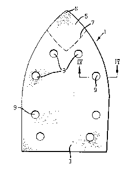
Figure 1 is a plan view of an abrasive sheet according
to the present invention;
Figure 2 is a plan view of the sheet of Figure 1 with
10 the tip portion of the sheet separated from the body portion
of the sheet;
Figure 3 is a side view of the sheet of Figure 1; and
Figure 4 is an enlarged sectional side view in the
direction IV-IV shown in Figure 1.
With reference to the drawings, an iron-shaped abrasive
sheet 1 comprises a body portion 3 and a tip portion 5. The
sheet 1, during manufacture, is simply cut from a third-size
abrasive sheet. A line of perforations 7 is also formed
20 during manufacture to define the extent of the tip portion.
The tip portion 5 is, however, still attached to the body
portion 3 at the end of the manufacture of the abrasive
sheet 1, so that a complete sheet is purchased by a user of
a sanding or polishing machine with a pre-defined working
25 pOil~t 11.
A plurality of apertures 9 are formed in the sheet 1
through which dust and debris can be removed by a suction
device of a sanding machine, during use. The arrangement of
30 apertures 9 will, of course, need to be designed to satisfy
the suction ducts formed in the sanding machine with which
the abrasive sheet is to be used.
As can be seen from Figure 1, the tip portion 5 of the
35 abrasive sheet 1 has edges which are shaped to complement

21 S61~9
the edges of the body portion 3 to define a complete
iron-shape, as shown. Further, if the tip portion 5 is
removed from the body portion 3 by tearing of the
perforations 7, as shown in Figure 2, the tip portion 5 can
5 be rotated through an angle of, say, 90 and replaced in
position adjacent the body portion 3 to produce, once again,
an iron-shaped abrasive sheet 1. The working point 11 of
the abrasive sheet 1 will, however, have changed.
As shown in the Figures, the tip portion 5 has four
working points 11. Hence, the tip portion 5 can be rotated
three times after a working point 11 has been worn out
before the complete tip portion becomes useless. This is
clearly a significant advantage over the triangular sheets
15 of the prior art.
As can be seen from Figure 4 of the drawings, the
abrasive sheet 1 comprises a support medium 13, such a mesh
or web, carrying on one side a layer 15 of abrasive material
20 in a resin and on the other side a layer 17 of loops or eyes
of a VELCRO-type fastening system. The hooks or eyes of the
layer 17 are designed to cooperate with hooks on a base (not
shown) of a sanding machine to hold the abrasive sheet 1 in
position on the base of the sanding machine. By using a
25 VELCRO-type fastening system, the tip portion 5 can easily
be removed, rotated and reinstated in position on the base
of the sanding machine.
Although not specifically disclosed in the drawings,
tip portions 5 having two, three, five, six, seven etc
30 working points 11 could, in theory, alternatively be used.
It will of course be under stood that the present
invention has been described above purely by way of example,
and that modifications of detail can be made within the
35 scope of the invention.

Representative Drawing
A single figure which represents the drawing illustrating the invention.
Administrative Status

2024-08-01:As part of the Next Generation Patents (NGP) transition, the Canadian Patents Database (CPD) now contains a more detailed Event History, which replicates the Event Log of our new back-office solution.

Please note that "Inactive:" events refers to events no longer in use in our new back-office solution.

For a clearer understanding of the status of the application/patent presented on this page, the site Disclaimer , as well as the definitions for Patent , Event History , Maintenance Fee  and Payment History  should be consulted.

Event History

Description Date
Inactive: Expired (new Act pat) 2015-08-16
Inactive: IPC from MCD 2006-03-11
Grant by Issuance 2001-11-27
Inactive: Cover page published 2001-11-26
Inactive: Final fee received 2001-08-14
Pre-grant 2001-08-14
Notice of Allowance is Issued 2001-07-09
Letter Sent 2001-07-09
Inactive: Approved for allowance (AFA) 2001-06-29
Inactive: Correspondence - Formalities 1999-02-08
Amendment Received - Voluntary Amendment 1998-10-15
Letter Sent 1998-09-09
Inactive: Status info is complete as of Log entry date 1998-09-08
Inactive: Application prosecuted on TS as of Log entry date 1998-09-08
All Requirements for Examination Determined Compliant 1998-07-31
Request for Examination Requirements Determined Compliant 1998-07-31
Application Published (Open to Public Inspection) 1996-02-26

Abandonment History

There is no abandonment history.

Maintenance Fee

The last payment was received on 2001-08-07

Note : If the full payment has not been received on or before the date indicated, a further fee may be required which may be one of the following

  • the reinstatement fee;
  • the late payment fee; or
  • additional fee to reverse deemed expiry.

Please refer to the CIPO Patent Fees web page to see all current fee amounts.

Owners on Record

Note: Records showing the ownership history in alphabetical order.

Current Owners on Record
BLACK & DECKER INC.
Past Owners on Record
COLIN PUGH
ERIC COCKBURN
MICHAEL MARTIN
Past Owners that do not appear in the "Owners on Record" listing will appear in other documentation within the application.
Documents

To view selected files, please enter reCAPTCHA code :


To view images, click a link in the Document Description column. To download the documents, select one or more checkboxes in the first column and then click the "Download Selected in PDF format (Zip Archive)" or the "Download Selected as Single PDF" button.

List of published and non-published patent-specific documents on the CPD .

If you have any difficulty accessing content, you can call the Client Service Centre at 1-866-997-1936 or send them an e-mail at CIPO Client Service Centre.


Document
Description 
Date
(yyyy-mm-dd) 
Number of pages   Size of Image (KB) 
Cover Page 2001-10-24 1 32
Abstract 1996-02-26 1 19
Cover Page 1996-04-17 1 16
Claims 1996-02-26 2 46
Description 1996-02-26 5 223
Drawings 1996-02-26 1 20
Claims 1998-10-15 2 42
Representative drawing 1998-03-06 1 6
Representative drawing 2001-10-24 1 5
Acknowledgement of Request for Examination 1998-09-09 1 194
Commissioner's Notice - Application Found Allowable 2001-07-09 1 165
Correspondence 1999-02-08 1 30
Correspondence 2001-08-14 1 50