Note: Descriptions are shown in the official language in which they were submitted.
2~~ ~~~~
-. WO 94/18927 PCT/US94/01767
1
Absorbent Article Having An Improved Leg Closure
FIELD OF THE INVENTION
The present invention relates to absorbent articles such as diapers,
incontinent
briefs, pull-on diapers, diaper holders, and the like, and more particularly,
to
absorbent articles having elastic leg features providing dynamic fit about the
wearer
as well as improved comfort characteristics of the absorbent article.
BACKGROUND OF THE INVENTION
The major function of absorbent articles such as disposable diapers and
incontinent briefs or undergarments is to absorb and contain body exudates.
Such
articles are thus intended to prevent body exudates from soiling, wetting, or
otherwise contaminating clothing or other articles, such as bedding, that come
in
contact with the wearer. Contemporary disposable diapers have a topsheet, a
backsheet, an absorbent core, and elasticized side flaps with one or more
elastic
members adjacent the longitudinal edge of the diaper to form elasticized leg
openings. These elasticized side flaps prove effective generally to prevent
wicking
and overflow from the fluid laden diaper to clothing contacting the edges of
the
diaper in that the elasticized side flaps present a fluid impervious barrier
between the
edge of the diaper and the contacting clothing, and in addition, provide a
gasketing
action about the legs of the wearer to maintain a seal about the leg and
minimize
gaPP~ng~
With regard to pull-on diapers such as training pants, have become popular,
especially for use on toilet-training children. In the past some training
pants have
been made elastically extensible using stretchable side panel disposed in the
training
pants such that the waist opening and leg openings having such elasticized
side flaps
are at least partially encircled with elasticized bands. Another type of pull-
on diapers'
stretchable side panel is formed by attaching discrete stretchable members to
the edge
of each side flap of the disposable garment in the front waist area and the
rear waist
area. While the stretchable side panel described above are useful to form pull-
on
diapers, it has been found that the wide stretchable side panels are
preferable to
sustain wide range dynamic fit.
However, while the stretchable side panel should be attached to the edge of
the side flap, or the stretchable side panel should be associated to the side
flap, the
width of such stretchable side panels and the width of the elasticized side
flap are
considered as parameters to be balanced in order to provide an appropriate
waist fit
range in the waist opening, and an effective gasketing action about leg
openings.
~~ 56~~2 v
width of such stretchable side panels and the width of the elasticized side
flap are
considered as parameters to be balanced in order to provide an appropriate
waist fit
range in the waist opening, and an effective gasketing action about leg
openings.
Thus, it was difficult to maximize functions of the stretchable side panels
and the
elasticized side flaps through maximization of the balanced width between the
stretchable side panel and the elasticized side flaps.
Furthermore, such stretchable side panel is being applied to a diaper having a
closure system such as an adhesive tape fastening system for a closure of a
front
portion and a rear portion of the diaper, the above difficulty is found among
any type
of absorbent articles having such stretchable side panel.
Therefore, it is an object of an aspect of the present invention to provide an
absorbent article which has enough width of the stretchable side panels and
enough
width of the elasticized leg openings at need, so as to maximize both dynamic
fit
range in the waist opening and improve gasketing action along the leg
openings.
SUMMARY OF THE INVENTION
According to an aspect of the present invention, an absorbent article
comprises
an absorbent chassis, a pair of side flaps, a pair of side panel, a pair of
longitudinal
extended leg cuff. The absorbent chassis has a front portion, a rear portion,
a crotch
portion joining the front portion and the rear portion, and a pair of side
edges in the
longitudinal direction throughout the front, crotch and rear portion. A pair
of side
flaps extend outwardly from each side edge of the absorbent chassis, each side
flap
having a side edge. A pair of side panels extend outwardly from the side edge
of the
side flap in the front portion and the rear portion. A pair of longitudinal
extended leg
cuffs are connectively associated with the absorbent chassis along the side
flap in the
crotch portion and extending longitudinally at least partially into the front
portion and
the rear portion. Each of extended leg cuffs has a free distal edge remote
from the
side edge of the side flap at least in the crotch portion so as to extend
outwardly from
the side flap. Each of the extended leg cuffs comprises a spacing means
disposed in at
least the crotch portion for spacing the distal edge upwardly away from said
absorbent
chassis.
2a
Another aspect of this invention is as follows:
An absorbent article comprising:
an absorbent chassis having a front portion, a rear portion, a crotch portion
joining the front portion and the rear portion, and a pair of side edges in
the
longitudinal direction throughout the front, crotch and rear portion;
a pair of side flaps extending outwardly from each side edge of the absorbent
chassis, each side flap having a side edge;
a pair of side panels extending outwardly from the side edge of the side flap
in
the front portion and the rear portion; and
a pair of longitudinal extended leg cuffs being connectively associated with
the absorbent chassis along the side flap in the crotch portion and extending
longitudinally at least partially into the front portion and the rear portion;
each of extended leg cuffs having a free distal edge remote from the
side edge of the side flap at least in the crotch portion so as to extend
outwardly from the side flap; and
each of the extended leg cuffs comprising a spacing means disposed in
at least the crotch portion for spacing said distal edge upwardly away from
the
absorbent chassis.
BRIEF DESCRIPTION OF THE DRAWINGS
While the specification concludes with claims particularly pointing out and
distinctly claiming the subject matter which is regarded as forming the
present
invention, it is believed that the invention will be better understood from
the
c'.'~'~: ,',
z~~~~ ~~
_. WO 94/18927 PCT/US94/01767
3
following description which is taken in conjunction with the accompanying
drawings
in which like designations are used to designate substantially identical
elements, and
in which:
Figure 1 is a perspective view of the disposal pull-on diaper embodiment of
the present invention in a typical in-use configuration as it would be applied
to a
wearer;
Figure 2 is a plan view of the chassis of the pull-on diaper embodiment of the
present invention having portions cut away to reveal the underlying structure,
the
surface which will form the outer surface of the disposable garment facing
away from
the viewer;
Figure 3 is a fragmentary sectional view taken along section line 3-3 of
Figure
2;
Figure 4 is a fragmentary sectional view taken along section line 4-4 of
Figure
2.
Figure 5 is a fragmentary sectional view taken along section line 5-5 of
Figure 2.
DETAILED DESCRIPTION OF THE INVENTION
As used herein, the term "absorbent article" refers to devices which absorb
and contain body exudates, and, more specifically, refers to devices which
are. placed
against or in proximity to the body of the wearer to absorb and contain the
various
exudates discharged from the body. The term "disposable" is used herein to
describe
absorbent articles which are not intended to be laundered or otherwise
restored or
reused as an absorbent article (i.e., they are intended to be discarded after
a single
use and, preferably, to be recycled, composted or otherwise disposed of in an
environmentally compatible manner). A "unitary" absorbent article refers to
absorbent articles which are formed of separate parts united together to form
a
coordinated entity so that they do not reduire separate manipulative parts
like a
separate holder and liner. A preferred embodiment of the unitary disposable
garment
of the present invention, disposable pull-on diaper 20, is shown in Figure 1.
The
pull-on diaper 20 of Figure 1, comprise an absorbent chassis 21, stretchable
side
panels 23, side seams 25, and dual leg cuffs 27 about leg openings 28.
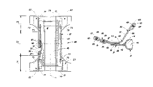
WO 94/18927 215 6 4 8 2 PCT/US94/01767
4
Figure 2 is a partially cut-away perspective view of the disposable pull-on
diaper 20 of Figure 1, prior to the front portion 29 and the rear portion 31
of the
absorbent chassis 21 being joined together by the side seams 25. The absorbent
chassis 21 of the present invention preferably has a symmetric, modified hour-
glass
shape. The absorbent chassis 21 will have at least a front portion 29, a rear
portion
31, a crotch portion 33, longitudinal side regions 35, and a stretchable side
panel 23
operatively attached to the side flaps 37 in the front portion 29 and the rear
portion
31. The side flaps 37 are formed from the extension of the backsheet 39 and
the
topsheet 41 extending outwardly from and along the side edges 43 of the
absorbent
core 45 in at least the crotch portion 33. The side flap 37 of the present
invention is
relatively narrower than a side flap 37 being elasticized with one or more
elastic
members as is known in the art. The dual leg cuffs 27 comprise a stand-up
barrier
cuff 50 and an extended leg cuff 60 which will be described in greater detail
herein
below.
EXTENDED LEG CUFF
As shown in Figs. 2 and 3, the extended leg cuffs 60 of the present invention
provide dynamic fit and skin contort as well as a structure to restrain the
free flow of
body exudates along the topsheet 41 and to hold and contain such exudates
within
the diaper 20 and to provide a gasketing action about the wearer. Each
extended leg
cuff 60 is a flexible member 61 having a proximal edge 63 and a distal edge
65. As
used herein, the term "flexible" refers to materials which are compliant and
will
readily conform to the general shape and contours of the body. In addition, if
the
spacing means 67 comprises one or more elastic members, the extended leg cuffs
60
must be contractible so that the distal edges 65 may be sufficiently spaced
away from
the topsheet 41. The extended leg cuffs 60 may be manufactured from a wide
variety
of materials such as polypropylene, polyester, rayon, nylon, foams, plastic
films,
formed films, elastic laminates and elastic foams. A number of manufacturing
techniques may be used to manufacture the extended leg cuffs 60. For example,
the
extended leg cuffs 60 may be woven, non-woven, spunbonded, carded, a laminate
of
a non-woven polypropylene material secured to a liquid impermeable
polyethylene
film, or the like as is known in the art.
As shown in Figs. 2 and 3, the extended leg cuff 60, and more particularly,
the proximal edge 63, is disposed adjacent to and preferable inboard of the
longitudinal edge 69 of the diaper 20. The term "inboard" is defined as the
direction
toward the centerline 71 of the diaper 20. The proximal edge 63 is preferably
disposed inboard of the longitudinal edge 69 so that exudates, especially
loose fecal
WO 94/18927 PCT/US94/01767
material which is not easily absorbed and tends to float along the topsheet
41, will
contact the extended leg cuff 60 before it can contact the edges 69 of the
diaper 20.
Thus, the proximal edge 63 is preferably disposed between the longitudinal
edge 69
and the longitudinal centerline 71 of the diaper 20, more preferably, between
the
longitudinal edge 69 and the side edge 43 of the absorbent core 45 in at least
the
crotch portion 33 of the diaper 20. Most preferably, the proximal edge 63 is
disposed along the side of the longitudinal edge 69 in at least the crotch
portion 33 of
the diaper 20. (It should be noted that if the stand-up barrier cuffs 50 are
elasticized
by one or more flap elastic members to form a stand-up leg gasketing cuff
adjacent
each the side edge 43 of the absorbent core 45, as is known in the art, then
the
proximal edge 63 of the extended leg cuff 60 is preferably positioned between
the
proximal edge 63 of the stand-up barrier cuff 50 and the longitudinal edge 69
in at
least the crotch portion 33.)
The proximal edges 63 and the distal edges 65 of the extended leg cuff 60 are
in a spaced relation to each other and define the effective width of each of
the
extended leg cuffs 60. The proximal edges 63 and the distal edges 65 may be in
a
parallel, nonparallel, rectilinear or curvilinear relationship. In addition,
each of the
extended leg cuffs 60 may have a variety of different cross-sectional areas
including
circular, square, rectangular or any other shape. Preferably, the proximal
edge 63 is
spaced from the distal edge 65 in a parallel and rectilinear relationship. The
effective
width of the extended leg cuff 60 is an important parameter in reducing
leakage of
body exudates out of the diaper 20. If the effective width of the extended leg
cuff 60
is too small, then gaps will be formed between the leg of the wearer and the
distal
edge 65 such that liquids may flow over the distal edge 65 to the periphery 73
of the
diaper 20. The extended leg cuff 60 of the present invention does not affect
to the
width of stretchable side panel 23 while the side flap 37 comprises no elastic
members for providing gasketing action and the flap 37 is relatively narrow.
Thus,
the extended leg cuff 60 can have a relatively wide width at need so as to
provide an
effective gasketing action. Of course, the effective width should be
dimensionalized
as the size of the wearer increases or decreases, particularly with adult
wearers.
The distal edge 65 of each extended leg cuff 60 is preferably not secured to
any underlying elements of the diaper 20 in at least the crotch portion 33 so
that it
may be spaced away from the topsheet 41. The distal edge 65 is preferably
spaced
away from the topsheet 41 so that the extended leg cuff 60 is easier to apply
to the
wearer and ensures that the fit of the extended leg cuff 60 is in the "no
motion" zone
in the crotch portion 33 with a snug fit about the wearer's buttocks. As used
herein,
WO 94/18927 ~ PCT/US94/01767
G
"spaced" includes embodiments wherein the distal edges 65 may assume one or
more
positions relative to the topsheet 41 including at some times assuming a
position
adjacent the topsheet 41.
The distal edge 65 of each extended leg cuff 60 is disposed inboard of the
proximal edge 63, preferably outboard of the proximal edge 63 in the front
portion
29 and the rear portion 31, so as to avoid gaps may be formed between the leg
of the
wearer and the distal edge 65, and present a more effective barrier against
the flow of
exudates. The term "outboard" is defined as the direction away from the
centerline
71 of the diaper 20 that is parallel to the respective edge of the diaper 20
along which
the extended leg cuff 60 is disposed. (i.e., the direction opposite from the
direction
defined by the term "inboard. ") The distal edges 65 are maintained outboard
of the
proximal edges 63 in both the front portion 29 and the rear portion 31 by a
closing
means 75 so as to obviate their inversion. As seen in Figs. 2, 3 and 4, in a
preferred
embodiment of the present invention, the closing means 75 is located in a
closure
zone 77 which is disposed outboard of the side flaps 37 and, in the same
embodiment, or in another preferred embodiment of the present invention, at
least a
portion of the closing means 75 is positioned above at least a portion of the
stretchable side panel 23.
The distal edges 65 are also shown in Figs. 2 and 4, to be disposed parallel
to
each other and perpendicular to the end edge 79 of the diaper 20 in the front
portion
29 and the rear portion 31. While this is a preferred embodiment, the distal
edges 65
may alternatively be angled toward or away from each other, especially toward
each
other if the extended leg cuffs 60 are manufactured from a material having
less
extensibility, such that the distal edges 65 are disposed non-perpendicular to
the end
edges 79. Angling the extended leg cuffs 60 relative to the end edge 79 may
assist in
allowing the extended leg cuff 60 to curve outwardly with expanded stretchable
side
panels 23 during use so as to provide snug fit along leg opening 28.
The distal edges 65 are preferably laterally spaced apart from each other in
the crotch portion 33. The lateral spacing of the distal edges 65 is
especially
important in the crotch portion 33 to provide easiness on application to the
wearer
and ensure that the fit of the extended leg cuffs 60 outwardly extended from
the
centerline 71 of the diaper 20, with a snug fit. Of course, the lateral
spacing should
be dimensionalized as the size of the wearer increases or decreases,
especially for
adult wearers.
WO 94/18927 ~ ~ ~ v PCT/US94/01767
7
A preferred embodiment of the diaper 20 shown in FIG. 1 is provided with
each of the extended leg cuffs 60 joined to the side flaps 37 of the diaper
20. The
term "joined" includes any means for securing the extended leg cuff 60 to the
diaper
20, and includes embodiments wherein the extended leg cuffs 60 are separate
members directly or indirectly secured to the side flaps 37 or embodiments
wherein
the extended leg cuffs 60 are constructed from the same member or material as
an
element of the diaper 20 such as stand-up barrier cuff 50 so that the extended
leg
cuffs 60 are a continuous and undivided element of the stand-up barrier cuff
50. The
extended leg cuffs 60 may alternatively be joined to the backsheet 39, the
topsheet
41, or any combination of these or other elements of the diaper 20. In the
preferred
embodiment, the extended leg cuffs 60 are joined with the side flaps 37
(directly to
the portion of the topsheet 41 and backsheet 39 forming the side flap 37 ) by
the seal
means 81 such as adhesive to form the proximal edge 63, the distal edge 65
being
formed by folding an end of the material 61 back upon itself and being secured
to
another segment by the distal attachment means 83. Preferably, the end of the
material 61 is back upon itself and sealed to the distal edge 65 by the seal
means,
more preferably, seated to the innerface or outerface of the backsheet 39 of
the side
flap 37 by seal means as shown in Fig. 3. In the preffered embodiment shown in
Fig.
3, the extended leg cuff 60 are constructed from the same material of the
stand-up
barrier cuff 50. Preferred material of such preferred embodiment is 20 gsy
hydrohobic polypropylene carded nonwoven.
The proximal edges 63 and the side flaps 37 are joined together in any
suitable manner. As used herein, the term "joined" encompasses configurations
whereby the proximal edges 63 are directly secured to the side flap 37 by
affixing the
proximal edges 63 directly to the side flap 37 and configurations whereby the
proximal edges 63 are indirectly secured to the side flap 37 by affixing the
proximal
edges 63 to intermediate members which in turn are affixed to the side flap
37. In a
preferred embodiment) the proximal edges 63 and the side flaps 37 are directly
secured to each other at least in the crotch portion 33 by the seal means 81.
The seal means 81 of the present invention for joining the proximal edges 63
to the side flaps 37 are shown in FIG.3. The seal means 81 provide a seal
along the
proximal edge 63 to present a barrier to the wicking of liquids through the
topsheet
41. While the topsheet 41 or the absorbent core 45 may extend beyond the seal
means 81, protection against leakage of liquids emanating from the edges of
the
absorbent core 45 or wicking along the topsheet 41 may be enhanced by making
the
topsheet 41 or the absorbent core 45 not extend beyond the proximal edge 63.
The
WO 94118927 PCTJUS9410I767
seal means 81 may be anv means for securing the proximal edees 63 to the side
flaps
37 such as adhesives, heat/pressure sealing, ultrasonic bonding, pressure
sensitive
adhesive double coated tapes, or any other means or methods as are known in
the
art. The seal means 81 are preferably three adhesive lines or spiral lines
consisting of
hot melt adhesive such as adhesives manufactured by Eastman Chemical Products
Company of Kingsport, Tennessee and marketed under the trade name Eastbond A-3
or by Century Adhesives, Inc. of Columbus, Ohio and marketed under the trade
name Century 5227. In the preferred embodiment) the seal means 81 consists of
a
nonwoven fabric strip enclosing elastomeric adhesive.
The spacing means 67 for spacing the distal edge 65 away from the topsheet
41) is any member which gathers, contracts, stiffens) shortens or otherwise
acts on
the extended leg cuff 60 so as to cause the extended leg cuffs 60 to stand up
to
provide easiness on application to the wearer and a gasketing action about the
buttocks of the wearer to provide a snug fit. -
As shown in Figs. 2 and 3, the spacing means 67 preferably comprises elastic
members operatively associated with each of the extended leg cuffs 60 adjacent
the
distal edge 65. The elastic members 67 are preferably secured to the extended
leg
cuff 60 in an elastically contractible condition so that in a normally
unrestrained
configuration, the elastic members 67 effectively contract or gather the
distal edge 65
of the extended leg cuff 60. The elastic members 67 can be secured to the
extended
leg cuff 60 in an elastically contractible condition in at least two ways as
is discussed
in U. S. Pat. No. 3,860,003 entitled "Contractible Side Portion For Disposable
Diaper", which issued to Kenneth B. Buell on Jan. 26, 1974.
In addition, the length of the elastic member 67 in general is
dictated by the diaper design. In the embodiment illustrated in FIG. 2, the
elastic
member 67 extends along essentially the entire length of the extended leg cuff
60 in
the crotch portion 33, although other lengths are cognizable.
As shown in Figs. 2 and 3) the elastic member 67 is operatively associated
with the extended leg cuff 60 by securing it within the extended leg cuff 60
with an
elastic attachment mea ns 85. The elastic attachment means 85 should be
flexible and
of sufficient adhesiveness to hold the elastic member 67 in its stretched
condition.
While the elastic members 67 may be secured to the extended leg cuff 60
adjacent
only the end of the elastic member 67) it is preferable to secure the entire
length of
the elastic member 67 to the extended leg cuff 60. The elastic attachment
means 85
herein are preferably glue beads made of hot melt adhesive such as marketed by
fA
WO 94118927 PCT/US94/01767
9 ~~ ~~~~2
Findley Adhesives Incorporated, Elmgrove, Wisconsin, as Findley Adhesives 581,
although the elastic members 67 may be affixed to the extended leg cuff 60 in
any of
several other ways which are well known in the art. For example, the elastic
members 67 may be ultrasonically bonded or heat/pressure sealed into the
extended
leg cuff 60 using a variety of bonding patterns) or the elastic members 67 may
simply
be glued to the extended leg cuffs 60. A more detailed description of the
manner in
which the elastic members 67 may be positioned and secured to the extended leg
cuff
60 can be found in U.S. Pat. No. 4,081,301, entitled "Method and Apparatus for
Continuously Attaching Discrete, Stretched Elastic Strands 'to Predetermined
Isolated Portions of Disposable Absorbent Products" which issued to Kenneth B.
Buell on Mar. 28) 1978, and in U. S. Pat. No. 4,253,461, entitled "Absorbent
Brief'
issued to Danny L. Strickland and Ronald B. Visscher on Mar. 3, 1981 .
It should be noted that one or more (a
plurality of) elastic members 67 can be used to elasticize each extended leg
cuff 60.
Preferably, one or two elastic members 67 are used to elasticize each extended
leg
cuff 60.
An elastic member 67 which has been found suitable is an elastic strand
having a cross section of 0.18 mm by 1.5 mm and made from natural rubber as
available from Easthampton Rubber Company of Stewart) Virginia, under the
trademark L-1900 Rubber Compound. Other suitable elastic members 67 can be
made from natural rubber, such as elastic tape sold under the trademark
Fulflex 9411
by Fulflex Company of Middletown) Rhode Island. The spacing elastic member 67
may also comprise any heat shrinkable material as is well known in the art.
Other
suitable elastic materials may comprise a wide variety of materials as are
well known
in the art include elastomeric films, polyurethane films, LycraT"",
elastomeric foams and
formed elastic scrim. In the preferred embodiment, the elastic members 67 and
the
elastic attachment means 85 can be formed by an adhesive strip stretched
having a
thickness of 0.5 mil as available from Findlay Adhesives Incorporated, Elm
Grove,
Wisconsin as Findley Adhesives 581) sold under trademark H 2330.
In addition, the elastic members 67 may take a multitude of configurations.
For example, the width of the elastic members 67 may be varied; the elastic
members
67 may comprise a single strand or several parallel or non-parallel strands of
elastic
material; or the elastic members 67 may be rectilinear or curvilinear.
The spacing means 67 for spacing the distal edge 65 away from the topsheet
41 may alternatively comprise several other elements. For example, the
extended leg
~A
WO 94118927 PCTIUS94I01767
cu. 50 may have stiffening means disposed in or on each extended leg cuff 60.
The
sti~ening means must be sufficiently stiff so that the distal edge 65 is
spaced away
from the topsheet 41. Suitable materials for the stiffening means include
foams) non-
woven fabrics, batting) polyethylene film, foamed films) spray glues, foamed
elastomerics, polyester) polyurethane) or high loft materials.
The spacing means 67 may also comprise means for shortening the length of
the distal edge 65 in comparison to the length of the edges of the diaper 20.
The
distal edge 65 can be shortened by making a fold or pleat in the distal edge
65. This
fold or pleat is secured by any of the holding means well known to those of
ordinally
skill in the art) such as adhesives or heat sealing. Alternatively, a section
may be cut
out of the distal edge 65 and the resultant edges brought together to form a
butt or
lap joint. The distal edge 65 may also be shortened by attaching a length of
the distal
edge 65 to the topsheet 41 at a position different from where the distal edge
65
would lie when the diaper 20 is in a flattened out condition. Other shortening
techniques as are known in the art may also be used.
The closing means 75 for securing the front end and the rear end,
respectively, of the extended leg cuff 60 closed are shown in FIGS. 2 and 4.
The
closing means 75 provide a more comfortable fit for the wearer and secure the
distal
edges 65 of the extended leg cuff 60 in the proper position to form an
sufficient
gasketing cuff. In a preferred embodiment, the closing means 75 are disposed
in the
front portion 29 and in the rear portion 31. The remaining portions of the
distal
edges 65 are preferably not secured to any underlying structure of the diaper
20 so
that the distal edges 65 are left freely operable. In a preferred embodiment
shown in
Fig 2, the closure zones 77 are formed on the above of the stretchable side
panel 23
adjacent to the leg opening 28 (adjacent to the crotch portion 33 ). This
construction
is preferred so as to create a snug fit about the buttocks of the wearer to
especially
prevent leakage from a joint of the stretchable side panel 23 and the extended
leg
cuff 60 as well as flexibility on width of the stretchable side panel 23. In
the
preferred embodiment) the closing means 75 closed entire length of the front
end and
the rear end overlapped on the front ear and the rear ear respectively.
While the closing means 75 may comprise any of several securement means
as are known in the art such as ultrasonic bonds or heat/pressure bonds or
seals using
a variety of bonding patterns) or adhesives and/or glues, the closing means 75
are
preferably adhesive beads consisting of hot melt adhesive such as manufactured
by
Eastman Chemical Products Company of Kingsport, Tenessee and marketed under
WO 94/18927 PCT/US94IOI767
.. 1,
the trade name Eastbond A-3 or by Century Adhesives, lnc. of Columbus. Ohio
and
marketed under the trade name Century 5227
STAND-UP BARRIER CUFF
The dual leg cuff 27 further comprises the stand-up barrier cuff 50. The
stand-up barrier cuff 50 may comprise several different embodiments for
reducing the
leakage of body exudates in the leg opening 28. U.S. Patent 4,909,803 entitled
"Disposable Absorbent Article Having Elasticized Flaps" issued to Aziz and
Blaney
on March 20, 1990, describes a disposable diaper having "stand-up" elasticized
flaps
(barrier cuffs) to improve the containment of the leg regions. U.S. Patent
4,695,278
entitled "Absorbent Article Having Dual Cuffs" issued to Lawson on September
22)
1987, describes a disposable diaper having dual cuffs including a gasketing
cuff and a
barrier cuff. U.S. Patent 4,704,115 entitled "Disposable Waist Containment
Garment" issued to Buell on November 3, 1987, discloses a disposable diaper or
incontinent garment having side-edge-leakage-guard gutters configured to
contain
free liquids within the garment.
The stand-up barrier cuffs 50 provide a barrier to restrain the free flow of
body exudates along the topsheet 41 and provide a structure to hold and
contain
such exudates within the diaper 20. Each of the stand-up barrier cuffs 50 is a
flexible
member having a proximal edge 91, a distal edge, an inboard surface, an
outboard
surface. In addition, if the spacing means comprises one or more spacing
elastic
members , the stand-up barrier cuffs 50 must be contractible so that the
distal edges
may be sufficiently spaced away from the topsheet 41 so that the channel
formed
along the stand-up barrier cuffs 50 is open to constrain, retain and hold body
exudates within the diaper 20. The stand-up barrier cuffs 50 may be
manufactured
from a wide variety of materials such as polypropylene, polyester) rayon)
nylon,
foams, plastic films, formed films) and elastic foams. A number of
manufacturing
techniques may be used to manufacture the stand-up barrier cuffs 50. For
example)
the stand-up barrier cuffs 50 may be woven, nonwoven) spunbonded) carded, or
the
like. A particularly preferred stand-up barrier cuff 50 comprises a
polypropylene
material containing no finish or surfactant to render it liquid impermeable. A
particularly preferred polypropylene material is manufactured by Crown
Zellerbach
Company as CelestraT«'. In the preferred embodiment, the stand-up barrier cuff
50
comprises the same member or material of the extended leg cuff 60 .
WO 94/18927 ~ PCT/US94/01767
12
As shown in FIGS. 2 and 3, the stand-up barrier cuffs 50 are disposed
adjacent each longitudinal edge 69 of the diaper 20 and are preferably
disposed
adjacent to an inboard of the extended leg cuffs 60; the proximal edges 91
being
preferably disposed inboard of the proximal edges 63 of the extended leg cuffs
60.
The proximal edge 91 of the stand-up barrier cuff 50 is preferably disposed
inboard
of the extended leg cuff 60, so that exudates, especially loose fecal material
which is
not easily absorbed and tends to float along the topsheet 41, will contact the
channel
portion of the stand-up barrier cuff 50 before it can contact the extended leg
cuff 60.
The stand-up barrier cuffs 50 are disposed adjacent the extended leg cuffs 60
to
provide a more effective dual restraint against the flow of body exudates. The
proximal edge 91 of the stand-up barrier cuff 50 is preferably disposed
between the
proximal edge 63 of the extended leg cuff 60 and the longitudinal centerline
71 of the
diaper 20. Most preferably, the proximal edge 91 of the stand-up barrier cuff
50 is
disposed between the proximal edge 63 of the extended leg cuff 60 and the side
edge
43 of the absorbent core 45 in at least the crotch portion 33 of the diaper
20.
The proximal edges 91 and the distal edges 93 of the stand-up barrier cuff 50
are in spaced relation to each other and define the effective width of each of
the
stand-up barrier cuffs S0. The proximal and distal edges 91, 93 may be in a
parallel,
nonparallel, rectilinear or curvilinear relationship. In addition, each of the
stand-up
barrier cuffs 50 may have a variety of different cross-sectional areas
including
circular, square, rectangular or any other shape such as that shown in Figs.
2, 3 and
4. Preferably, the proximal edges 91 are spaced from the distal edges 93 in a
parallel
and rectilinear relationship to provide stand-up barrier cuffs 50 having
uniform
effective widths.
As shown in Figs, 2, 3, and 5, the distal edges 95 of the stand-up barrier
cuff
50 are preferably disposed inboard of the proximal edges 91 of the stand-up
barrier
cuff 50 to present a more effective barrier against the flow of exudates. The
distal
edges 95 are maintained inboard of the proximal edges 91 by the closing means
103
so as to obviate their inversion. While the distal edges 95 may alternatively
be
disposed in other positions in relation to the proximal edges 91, such
positions are
not preferred.
The distal edges 95 are preferably not secured to any other element in at
least
the crotch portion 33 of the diaper 20 so that they may be spaced away from
the
topsheet 41. The distal edges 95 are preferably spaced away from the topsheet
41 so
that the stand-up barrier cuffs 50 may form a channel 101 to enhance the
~1~~~~z
WO 94118927 PCT/US94/01767
13
containment of the diaper 20. As used herein, "spaced" includes embodiments
wherein the distal edges 95 may assume one or more positions relative to the
topsheet 41 including at some times assuming a position adjacent the topsheet
41.
The distance between a distal edge 95 to the topsheet 41 is measured along a
line
drawn from the distal edge 95 to the closest part of the topsheet 41 when the
distal
edge 95 is positioned so as to be spaced away from the topsheet 41 as far as
possible
(i.e., in the elastically contracted position).
The stand-up barrier cuffs 50 are preferably hydrophobic and more preferably
liquid impermeable so as to prevent the strikethrough of body exudates. A
liquid
impermeable stand-up barrier cuff 50 retards the movement of liquid through
the
stand-up barrier cuff 50, thereby making it more leakage resistant. The stand-
up
barrier cuffs 50 may be rendered liquid impermeable in any manner well known
in the
art such as selectively treating the stand-up barrier cuffs 50, untreating the
stand-up
barrier cuffs 50, or by securing a separate material to the stand-up barrier
cuffs 50.
The stand-up barrier cuffs 50 may additionally be provided with absorbent
means
secured to or within the stand-up barrier cuff 50.
A preferred embodiment of the diaper 20 shown in Figs. 3, 4, and 5, is
provided with each of the stand-up barrier cuffs 50 joined to the side flaps
37 (i.e.,
the backsheet 39 ). The term "joined" includes any means for affixing the
stand-up
barrier cuffs 50 to the diaper 20, and includes embodiments wherein the stand-
up
barrier cuffs 50 are separate members directly or indirectly adjoined to the
side flaps
37 (i.e., integral) or embodiments wherein the stand-up barrier cuffs 50 are
constructed from the same member or material as an element of the diaper 20 so
that
the stand-up barrier cuffs 50 are a continuous and undivided element of the
side flaps
37 (i.e., unitary). The stand-up barrier cuffs SO may alternatively be joined
to the
backsheet 39, the absorbent core 45, the topsheet 41 or any combination of
these or
other elements of the diaper 20 such as the extended leg cuff 60 as discussed
before.
In a preferred embodiment, both the stand-up barrier cuffs 50 and the extended
leg
cuffs 60 are integral with the side flaps 37. The integral stand-up barrier
cuffs 50 and
extended leg cuff 60 are thus preferably formed by a single separate strip of
material
with an intermediate segment adjoined to the side flaps 37 by the seal means
81 such
as an adhesive to form the proximal edge 91, the distal edge being formed by
folding
an end of the material back upon itself and being secured to another segment
by the
distal attachment means , and the remaining portion of the material, the side
flap 37
portions; extending and terminating outboard of the proximal edges 91 and
preferably associated with the backsheet 39 by the seal means 81 to define a
portion
WO 94118927 PCTIUS94101767
1.1
of side fl~ 37 between the proximal edees 91 of the stand-up barrier cuff 50
and the
proximal edges 63 of the extended leg cuffs 60
The stand-up barrier cuffs 50 and the side flaps 37 (backsheet 39) are
adjoined together in any suitable manner. As used herein) the term "adjoined"
encompasses configurations whereby the stand-up barrier cuffs 50 are directly
secured to the side flaps 37 by affixing portions of the stand-up barrier
cuffs 50
directly to the backsheet 39, and configurations whereby the stand-up barrier
cuffs
50 are indirectly joined to the side flaps 37 by affixing them to intermediate
members
which in turn are affixed to the backsheet 39. In a preferred embodiment, the
stand-
up barrier cuffs 50 and the side flaps 37 are adjoined directly to the each
other by a
seal means 81 such as adhesive or any other attachment means such as
heat/pressure
sealing, ultrasonic bonding or any other methods as are known in the art. For
example, a uniform continuous layer of adhesive, a patterned layer of
adhesive) or an_
array of separate lines or spots of adhesive may be used. The seal means 81
is.
preferably a hot melt adhesive such as manufactured by Eastern Chemical
Products
Company of Kingsport, Tennessee and marketed under the tradename Eastbond A-3
or Century Adhesives, Inc. of Columbus, Ohio and marketed under the tradename
Century 5227. In the preferred embodiment, the seal means 81 consists of a
nonwoven fabric strip enclosing elastomeric adhesive. (It should be noted that
the
seal means 81 herein are preferably the same type of means as the seal means
81 for
joining the proximal edges 63 of the extended leg cuff 60 to the side flaps
37).
The seal means 81 for adjoining the proximal edges 91 of the stand-up barrier
cuffs 50 to the side flaps 37 provide a leakage-resistant seal along the
proximal edge
91 to present a barrier to the wicking of liquid through the topsheet 41 so as
to
prevent liquids from wicking underneath the stand-up barrier cuffs SO to the
edges of
the diaper 20.
The spacing means 105 for spacing the distal edges 95 away from the
topsheet 41 is any member which gathers, contracts, stiffens, shortens or
otherwise
acts on the stand-up barrier cuffs 50 so as to cause the stand-up barrier cuff
50 to
stand up to provide a channel 101 along the barrier cuff 50 that acts as a
constraint
against the leakage of exudates.
As shown in Fig. 3, the spacing means 105 preferably comprises a
spacing elastic member 105 operatively associated with each of the stand-up
barrier
cuffs 50 adjacent the distal edge 95. The spacing elastic member 105 is
preferably
WO 94/18927 PCT/US94I01767
r~ 15
secured to the stand-up barrier cuff 50 in an elastically contractible
condition so that
in a normally unrestrained confi'uration, the spacing elastic member 105
effectively
contracts or gathers the distal edge 95 of the barrier cuff 50 The spacing
elastic
member 105 can be secured to the stand-up barrier cuff 50 in an elastically
contractible condition in at least two ways as is discussed in the U.S. Pat.
No.
3,860,003 that issued to K. B. Buell.
The length of the spacing elastic member 105 in general is dictated by the
diaper design. In the preferred embodiment illustrated in FIG. 2) the spacing
elastic
members 105 extend essentially the entire length of the stand-up barrier cuff
50 in
the crotch portion 33. In the most preferred embodiment, the spacing elastic
members 105 extend beyond the crotch portion 33 any distance, including all
the way
to the end edges of the diaper 20, so as to provide the most effective spacing
of the
stand-up barrier cuffs 50 away from the topsheet 41.
As shown in FIG. 3, the spacing elastic member 105 is operatively associated
with the stand-up barrier cuff 50 by securing it within the stand-up barrier
cuff 50
with a spacing elastic attachment means 107. A detailed description of the
manner in
which the spacing elastic members 105 may be positioned and secured to the
stand-
up barrier cuffs 50 can be found in U.S. Pat. No. 4,081,301, issued to Buell
on
March 28, 1978, and in U.S. Pat. No. 4,253,461, issued to Strickland and
Visscher
on March 3) 1981. It should also
be noted that one or more spacing elastic members 105 can be used to
elasticize each
stand-up barrier cuff 50.
A spacing elastic member IOS which has been found suitable is an elastic
strand having a cross section of 0.18 mm by 1.5 mm and made from natural
rubber as
available from Easthampton Rubber Company of Stewart, Virginia) under the
trademark L-1900 Rubber Compound. Other suitable spacing elastic members 105
can be made from natural rubber) such as elastic tape sold under the trademark
Fulflex 9411 by Fulflex Company of Middletown, Rhode Island. The spacing
elastic
member 105 may also comprise any heat shrinkable elastic material as is well
known
in the art. Other suitable elastic matetial~ may comprise a wide variety of
materials
as are well known in the art include elastomeric films, polyurethane films,
elastomeric
foams and formed elastic scrim. In the preferred embodiment) the elastic
members
105 and the elastic attachment means 107 can be foamed by an adhesive strip
stretched having a thickness of 0.5 mil as available from Findlay Adhesives
~ri
a a i ii i i
2~.~648~
WO 94/18927 PCT/US94/01767 _
1G
Incorporated, Elm Grove, Wisconsin as Findley Adhesives 581, sold under
trademark H 2330.
In addition, the spacing elastic members 105 may take a multitude of
configurations. For example the width of the spacing elastic members 105 may
be
varied; the spacing elastic members 105 may comprise a single strand or
several
parallel or non-parallel strands of elastic material; or the spacing elastic
members 105
may be rectilinear or curvilinear.
The spacing means 105 for spacing the distal edges away from the topsheet
41 may alternatively comprise several other elements as described before for
the
spacing means of the extended leg cuff 60.
The closing means 103 for securing the distal edges 93 of the stand-up barrier
cuffs 50 together provide a more comfortable fit for the wearer and obviate
inversion
of the distal edges 93 of the stand-up barrier cuffs 50 during application and
use.
Inversion is generally defined as the inboard-disposed distal edges 93 turning
outwardly when the diaper 20 is applied to the wearer.
The closing means 103 are preferably adhesive beads consisting of hot melt
adhesives such as marketed by Eastman Chemical Products Company, Kingsport,
Tennessee, as Eastbond A-3 or Century Adhesives, Inc. of Columbus, Ohio as
Century 5227 although other closing means as are known in the art such as
ultrasonic
bonding or heat/pressure sealing may also be used.
The pull-on diaper 20 is applied to a wearer by placing the wearer's feet in
the
leg openings 28 and sliding the pull-on diaper up the legs into position, the
stand-up
barrier cuffs 50 and the extended leg cuff 60 should be disposed to provide
the
dispositions and functions described hereinbefore.
SIDE PANEL
The absorbent chassis 21 further comprises stretchable side panels 23 in the
front portion 29 and the rear portion 31. The stretchable side panel 23 are
separately
manipulative elements secured to the chassis 21, but can be formed from
extensions
of the chassis 21 materials. The stretchable side panel 23 provide an
elastically
extensible feature that provides a more comfortable and contouring fit by
initially
conformably fitting the disposable garment to the wearer and sustaining this
fit
throughout the time of wear well past when the disposable garment has been
loaded
WO 94/18927 PCT/US94101767
with exudates since the stretchable side panel 23 allow the sides of the
disposable
garment to expand and contract.
As shown in Figure 2) each stretchable side panel 23 comprises that portion
of the absorbent chassis 21 that extends laterally outwardly from and along
the
central portion 33 of the absorbent chassis 21 to the longitudinal side region
of the
absorbent chassis 21. The side panel 23 generally extends longitudinally from
the
end edge 109 of the absorbent chassis 21 to the portions of the longitudinal
edge 69
of the absorbent chassis 21 that forms the leg opening 28 (this segment of the
longitudinal edge being designated as leg edge ). The stretchable side panel
23 can
be formed by the portions of the topsheet 41 and the backsheet 39 that extend
beyond the side flap 37.
In a preferred embodiment) as shown in Figs. 4, the stretchable side panels 23
are formed by securing a piece of stretchable panel to the side edge 38 of the
side
flap 37 in the front portion 29 and the rear portion 31) so that the
stretchable side
panel 23 allow to be elastically extensible as desired in the lateral
direction (laterally
elastically extensible). As used herein, the team "elastically extensible"
means a
segment or portion of the chassis 21 that will elongate in at least one
direction
(preferably the lateral direction for the side panel) when tensional forces
(typically
lateral tensional forces of the side panel) are applied) and will return to
about its
previous size and configuration when the tensional forces are removed.
A more detailed description of such side panel 23 is shown in U.S. Patents
4,490,464; 4,938,753; and 4,938,757 all of which issued to Van Gompel, et al.
These patents disclose a pant-like garment formed by attaching discrete
stretchable
members to the edge of each side flap 37 of the disposable garment in the
front waist
area and the rear waist area. The discrete stretchable members are described
as being
made by stretching an elastic or stretchable layer to a selected elongation,
placing a
nonstretchable layer, such as a nonwoven, on the stretched layer, bonding the
layers
together, and allowing the layers to relax so that the nonstretchable layer is
gathered.
A methods for making a stretchable member is described in U.S. Patent
4,107,364,
issued to Sisson on August 15, 1978, U.S. Patent 4,209,563 issued to Sisson on
June
24, 1980) U.S. Patent 4,525,407 issued to Ness on 3une 25) 1985, U.S. Patent
4,834,741 issued to Sabee on May 30, 1989) European Patent Publication
409,315,
The Procter & Gamble Company, published January 23, 1991
A,
WO 94/18927
PC'TlUS94101767
~~ ~~~~2
SIDE SEAM
Referring again to Figure 1) the side seams 25 are preferably formed by
bonding together the longitudinal side region of stretchable side panel 23 of
the front
portion 29 and the longitudinal side region of the stretchable side panel 23
of the rear
portion 31. The seams 25 can be formed in a number of different ways. For
example, the seams 25 can be formed by bonding together portions of outwardly
extending longitudinal side regions to form an outwardly extending fin seam
using
any seam configurations that are known in the art. The bonding can be by any
suitable means known in the art; thus ultrasonic bonding, heat sealing)
adhesive
bonding, and the like. Example of such seaming techniques are disclosed in
U.S.
Patent 4,355,425 issued to Jones) et al. on October 26) 1982; U.S. Patent
4,619,649
issued to Roberts on October 28, 1986; U.S. Patent 4,909,804 issued to
Douglas) Sr.
on March 20, 1990.
ABSORBENT CHASSIS
The absorbent chassis 21 comprises a liquid pervious topsheet 41, a liquid
impervious backsheet 39 joined with the topsheet 41) an absorbent core 45
positioned between the topsheet 41 and the backsheet 39. Figure 2 shows a
preferred embodiment of the diaper 20 in which the topsheet 41 and the
backsheet 39
length and width dimensions generally larger than those of the absorbent core
45.
The topsheet 41 and the backsheet 39 extend beyond the edges 43 of the
absorbent
core 45. While the topsheet 41) the backsheet 39, and the absorbent core 45
may be
assemble in a variety of well known configurations, preferred diaper
configurations
are described generally in U.S. Patent 3,860,003 entitled "Contractable Side
Portions
for Disposable Diaper" which issued to Kenneth B. Buell on January 14, 1975;
and
Canadian Patent Application Serial No. 2,103,268, "Absorbent Article With
Dynamic
Elastic Waist Feature Having A Predisposed Resilient Flexural Hinge", Kenneth
B.
Buell et al.
The absorbent core 45 may be any absorbent means which is generally
compressible, conformable) non-irritating to the wearer's skin) and capable of
absorbing and retaining liquids such as urine and other certain body exudates.
As
shown : Figs. 2 and 3, the absorbent core 45 has the side edges 43) and waist
edges.
The abs _ : bent core 45 may be manufactured in a wide variety of sizes and
shapes
(e.g., rectangular, hourglass, "T"-shaped, asymmetric, etc.) and from a wide
variety
of liquid-absorbent materials commonly used in disposable diapers and other
absorbent articles such as comminuted wood pulp which is generally referred to
as
airfelt. Examples of other suitable absorbent materials include creped
cellulose
~A
WO 94118927 ~ ~ ~ ~ ~CT/US94~o17s7
l9
wadding; meltblown polymers including coform; chemically stiffened, modified
or
cross-linked cellulose fibers: tissue including tissue wraps and tissue
laminates;
absorbent foams; absorbent sponges; super absorbent polymers; absorbent
gelling
materials; or any equivalent material or combinations of materials. The
configuration
and construction of the absorbent core 45 may also be varied (e.g., the
absorbent
core 45 may have varying caliper zones) a hydrophilic gradient, a super
absorbent
gradient) or lower average density and lower average basis weight acquisition
zones;
or may comprise one or more layers or structures). The total absorbent
capacity of
the absorbent core 45 should, however, be compatible with the design loading
and
the intended use of the diaper 20. Further, the size and absorbent capacity of
the
absorbent core 45 may be varied to accommodate wearers ranging from infants
through adults. Exemplary absorbent structures for use as the absorbent core
45 are
described in U.S. Patent 4,610,678 entitled "High-Density Absorbent
Structures"
issued to Weisman et al. on September 9, 1986; U.S. Patent 4,673,402 entitled
"Absorbent Articles With Dual-Layered Cores" issued to Weisman et al. on June
16,
1987; U.S. Patent 4,888,231 entitled "Absorbent Core Having A Dusting Layer"
issued to Angstadt on December 19, 1989; and U.S. Patent 4,834,735, entitled
"High
Density Absorbent Members having Lower Density and Lower Basis Weight
Acquisition Zones") issued to Alemany et al. on May 30, 1989.
The backsheet 39 is positioned adjacent the garment surface of the absorbent
core 45 and is preferably joined thereto by attachment means (not shown) such
as
those well known in the art. For example, the backsheet 39 may be secured to
the
absorbent core 45 by a uniform continuous layer of adhesive, a patterned layer
of
adhesive, or an array of separate lines, spirals, or spots of adhesive.
Adhesives which
have been found to be satisfactory are manufactured by H. B. Fuller Company of
St.
Paul) Minnesota and marketed as HL-1258. The attachment means will preferably
comprise an open pattern network of filaments of adhesive as is disclosed in
U. S.
Patent 4,573,986 entitled "Disposable Waste-Containment Garment") which issued
to Minetola et al. on March 4) 1986, more preferably several lines of adhesive
filaments swirled into a spiral pattern such as is illustrated by the
apparatus and
methods shown in U. S. Patent 3,911,173 issued to Sprague, Jr. on October 7,
1975;
U. S. Patent 4,785,966 issued to Ziecker, et al. on Novemba 22, 1987; and U.
S.
Patent 4,842,666 issued to Werenicz on June 27, 1989.
Alternatively, the attachment means may comprise
heat bonds, pressure bonds, ultrasonic bonds, dynamic mechanical bonds, or any
,,
WO 94118927 PC'TNS94IOI767
other suitable attachment means or combinations of these attachment means as
are
known in the art.
The backsheet 39 is impervious to liquids (e.g., urine) and is preferably
manufactured from a thin plastic film, although other flexible liquid
impervious
materials may also be used. As used herein) the term "flexible" refers to
materials
which are compliant and will readily conform to the general shape and contours
of
the human body. The backsheet 39 prevents the exudates absorbed and contained
in
the absorbent core 45 from wetting articles which contact the diaper 20 such
as bed
sheets and undergarments. The backsheet 39 may thus comprise a woven or non
woven material, polymeric films such as thermoplastic films of polyethylene or
polypropylene) or composite materials such as a film-coated non woven
material.
Preferably, the backsheet is a thermoplastic film having a thickness of from
about
0.012 mm (O.Smil) to about 0.051 mm (2.0 mils). Particularly preferred
materials for
the backsheet include 1ZR8220 blown films and RR5475 cast films as
manufactured
by Tredegar Industries, Inc. of Terre Haute, IN. The backsheet 39 is
preferably
embossed and/or matte finished to provide a more cloth like appearance.
Further,
the backsheet 39 may permit vapors to escape from the absorbent core 45 (i.e.,
breathable) while still preventing exudates from passing through the backsheet
39.
The topsheet 41 is positioned adjacent the body surface of the absorbent core
45 and is preferably joined thereto and to the backsheet 39 by attachment
means (not
shown) such as those well known in the art. Suitable attachment means are
described with respect to joining the backsheet 39 to the absorbent core 45.
As used
herein, the term "joined" encompasses configuration whereby an element is
directly
secured to the other element by affixing the element directly to the other
element,
and configurations whereby the element is indirectly secured to the other
element by
affudng the element to intermediate members) which in turn are affixed to the
other
element. In a preferred embodiment of the present invention, the topsheet 41
24 and
the backsheet 39 are joined directly to each other in the diaper periphery and
are
indirectly joined together by directly joining them to the absorbent core 45
by the
attachment means (not shown).
The topsheet 41 is compliant, soft feeling, and non-irntating to the wearer's
skin. Further) the topsheet 41 is :uid per.~ious permitting liquids (e.g.,
urine) to
readily penetrate through its thickr. .;s. A suitable topsheet 41 may be
manufactured
from a wide range of materials, such as porous foams; reticulated foams;
aperture
plastic films; or woven or non woven webs of natural fibers (e.g., wood or
cotton
fibers)) synthetic fibers (e.g.) polyester or polypropylene fibers)) or a
combination of
natural and synthetic fibers. Preferably, the topsheet 41 is made of a
hydrophobic
'-
WO 94/18927 PCT/US94/01767
21
material to isolate the wearer's skin from liquids contained in the absorbent
core 45.
There are a number of manufacturing techniques which may be used to
manufacture
the topsheet 41. For example, the topsheet 41 may be a nonwoven web of fibers
spunbonded, carded, wet-laid, meltblown, hydroentangled, combinations of the
above, or the like. A preferred topsheet 41 is carded and thermally bonded by
means
well known to those skilled in the fabrics art. A preferred topsheet 41
comprises a
web of stable length polypropylene fibers such as is manufactured by Veratec,
Inc., a
Division of International Paper Company, of Walpole, Massachusetts under the
designation P-8.
While particular embodiments of the present invention have been illustrated
and described, it would be obvious to those skilled in the art that various
other
changes and modifications can be made without departing from the spirit and
scope
of the invention. It is therefore intended to cover in the appended claims all
such
changes and modifications that are within the scope of this invention.