Note: Descriptions are shown in the official language in which they were submitted.
WO 94/19432 ~ ~ ~ ~ PCT/US94/02241
- 1 -
FIRE STARTER AND METHOD OF MAKING SAME
BACKGROUND AND SUMMARY
This invention relates to a fire starter con-
struction, a method of making a fire starter, and a
package construction for use in packaging of fire start-
ers.
Fire starters in the form of a block of wax and
wood particles are l-:nown. This type of fire starter is
generally rectangular in cross-section, and is provided
in blocks of predetermined lengths. The block is placed
below a quantity of material to be burned, such as char-
coal or wood, and is ignited using a match or other flame
source. The wax and wood particles burn to ignite the
charcoal or wood. While this type of fire starter gener-
I5 ally functions to ignite such material, it is disadvanta-
geous in that a relatively large quantity of fire starter
material must be used to generate a sufficiently intense
flame for a long enough period of time to ignite the
material to be burned. Further, fire starters of this
type are cumbersome to package and sell at the retail
level.
It is also known in the prior art to provide a
metal platform onto which wood chips are placed. The
chips are either coated with wax or impregnated with a
combustible fuel. The platform is provided with open-
ings, and is placed onto a supporting surface, such as
the floor of a fireplace. The chips are then ignited,
and burning of the chips ignites the fireplace logs.
Again, this generally functions to ignite a fire, but is
disadvantageous in its requirement of a separate metal
platform which must be recovered from the ashes before
subsequent reuse in igniting a new fire. In addition,
the intensity of the flame generated by burning of the
chips is often insufficient to ignite fireplace logs.
It is an object of the present invention to
provide a fire starter which is extremely simple=in its
construction and operation, yet which provides highly
CA 02157001 2003-04-28
-2-
satisfactory performance in igniting combustible material such as charcoal or
logs.
Another object of the invention is to provide a method of making a fire
starter which is
likewise relatively simple, yet which results in a fire starter providing a
high level of
performance. A further object of the invention is to provide a fire starter
packaging
arrangement which efficiently and economically packages fire starters for
sale.
According to the present invention there is provided a fire starter,
consisting of a
mass of solid combustible material of a mixture of wax and wood particles and
having a
closed shape and a coplanar, common, upper horizontal surface, consisting of a
series of
spaced, inverted, frustro-conical sections connected together by a series of
inverted
triangular connecting sections, each frustro-conical section consisting of a
flared
outwardly diverging sidewalk at least two spaced apart feet, each having a
sidewall and a
bottom surface extending downwardly from the lower end of each frustro-conical
section
for engagement with a supporting surface, the frustro-conical sections and the
connecting
sections defining the upper surface, the sidewall of each inverted frustro-
conical section
defining an arcuate upper outer edge and an arcuate upper inner edge, each
connecting
section defining linear upper outer and inner edges, the linear outer edges
extending
between adjacent arcuate outer edges, and the linear inner edges extending
between
adjacent arcuate inner edges, the arcuate inner edges and the linear inner
edges defining
boundaries of an aperture extending substantially centrally through the upper
surface, the
frustro-conical sections forming laterally, outwardly opening air spaces
providing flow of
air to the aperture during combustion of the mass of solid combustible
material, each air
passage being inwardly convergent so as to accelerate air as it passes from
the exterior of
the fire starter into the aperture, wherein the mass of solid combustible
material defines an
outer veneer layer defining at least in part the outer surface of the mass of
solid
combustible material, the veneer layer consisting primarily of wax, and
wherein the wood
particles are distributed throughout an inner portion of the mass of solid
combustible
material located inwardly of the veneer layer.
In accordance with one aspect of the invention, a fire starter construction
provides
a mass of solid combustible material having an aperture therethrough. The fire
starter
includes support structure which supports the mass of material above a
supporting surface,
such as the floor of a fireplace or the lower grate of a grill. The support
structure includes
one or more air spaces located below the mass of material, for providing flow
of air to the
CA 02157001 2003-04-28
-2a-
aperture during combustion of the mass of material. The mass of material
consists of a
mixture of wax and wood particles, and is formed to a closed shape. The
aperture extends
substantially through the center of the closed shape defined by the mass of
material. The
mass of material is formed to provide an outer veneer layer, consisting
primarily of wax,
which defines the outer surfaces of the mass of material. The wood particles
are
distributed throughout an inner portion of the mass of material, located
inwardly of the
outer veneer layer. The mass of material is formed by placing a quantity of
wax and wood
particles into a mold while in a flowable state, and subjecting the quantity
of wax and
wood particles to pressure exceeding approximately 250 psi, preferably 700 psi
to 800 psi.
The mass of material is then solidified. The mass of material is preferably in
the form of a
ring-shaped member, and the support means is in the form of two or more spacer
elements
formed integrally with the ring-shaped member and extending downwardly
therefrom for
supporting the ring-shaped member above the supporting surface. The spacer
elements
WO 94/19432 ~ ~ ~ PCT/US94/02241
- 3 -
are spaced from each other to define passages therebe-
tween, for providing flow of air to the aperture during
combustion of the ring-shaped member. Each spacer ele-
ment defines a substantially flat lower surface for
placement on the supporting surface, and an inverted
conical wall extending upwardly from the flat lower
surface. The spacer elements are interconnected together
by connecting portions of the solid combustible material,
and the connecting portions are preferably provided with
an inverted triangular cross-section. The spacer ele-
ments and the connecting portions cooperate to define a
substantially planar upper surface on the ring-shaped
mass of material.
The invention further contemplates a method of
making a fire starter. The method involves providing a
mixture of wax and wood particles in a flowable state,
and forming the mixture to a shape providing an upper
mass of material having an aperture therethrough, and one
or more spaced downwardly extending support portions.
The mass of material is preferably formed to a shape a.::
summarized above. Thereafter, the mass of material is
solidified. The step of forming the mixture of wax and
wood particles is carried out by placing the mixture into
a mold having a cavity with a shape corresponding to the
final desired shape of the mass of material, and subject-
ing the mixture to pressure within the mold cavity in
excess of approximately 200 psi. Preferably, the mixture
is subjected to pressure in the range of 700 psi to 800
psi, which functions to cause the wood particles in the
mixture to migrate inwardly from the mold surfaces to
form the outer veneer layer consisting primarily of wax,
as summarized previously.
The invention further contemplates a package
for a plurality of fire starters constructed as summa
rized above. The package includes a substantially tubu
lar container having a bottom wall and one or more up-
standing side walls defining an internal cavity. A
~~~~oa~
WO 94/19432 r ; y ,~ ; ;A' ,, 'a ~ '_ PCT/US94/02241
- 4 -
plurality of fire starters are placed within the internal
cavity in vertical stacked relationship such that the
apertures in the fire starters are aligned with each
other. A retainer is placed through the aligned aper-
tures in the fire starters to retain the fire starters in
alignment with each other within the container cavity.
The container defines an open end opposite the bottom
wall, and a cap member is engageable with the container
at its open end to enclose the container cavity after
placement of the fire starters and the retainer therein.
In a particularly preferred arrangement, the retainer
consists of a rolled sheet of printed instructions. The
upstanding wall of the container is preferably formed of
a transparent material, so as to allow visual access to
the fire starters within the internal cavity of tile
container.
Various other features, objects and advantages
will be made apparent from the following description
taken together with the drawings.
E~IEF DESCRIPTION OF THE DRAWINGS
The drawings illustrate the best mode presently
contemplated of carrying out the invention.
In the drac.Tings
Fig. 1 is a front elevation view showing a fire
starter constructed according to the invention in use for
igniting logs in a fireplace;
Fig. 2 is a section view of the fire starter of
Fig. 1; '
Fig. 3 is an isometric view of the fire starter
of Figs. 1 and 2;
Fig. 4 is a bottom plan view of the fire start-
er of Figs. 1-3;
Fig. 5 is an enlarged partial cross-sectional
view showing a portion of the fire starter of Figs. 1-4;
Fig. 6 is a schematic diagram illustrating the
method steps involved in making the fire starter of Figs.
1-5;
WO 94/19432 ~ ~ ~ PCT/US94102241
- 5 -
Fig. 7 is a partial cross-sectional view
through a mold arrangement for producing the fire starter
of Figs. 1-5;
Fig. 8 is an isometric view showing a packaging
arrangement for packaging a number of fire starters
constructed according to the invention;
Fig. 9 is an exploded isometric view showing
the manner in which fire starters constructed according
to the invention are assembled into the packaging ar-
rangement of Fig. 8;
Fig. 10 is an isometric view showing the in-
struction sheet comprising a part of the packaging ar-
rangement of Figs. 8 and 9; and
Fig. 11 is a partial sectional view showing the
upper portion of the packaging arrangement of Fig. 8.
DETAILED DESCRIPTION OF THE INVENTION
Referring to Fig. 1, a fire starter 20 con-
structed according to the invention is shown positioned
below a fireplace grate 22 for igniting several logs,
shown generally at 24, supported by grate 22. Fire
starter 20 and grate 22 are positioned on a horizontal
floor 26 of the fireplace.
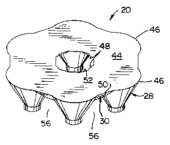
The construction of fire starter 20 is illus
trated in detail in Figs. 2-4. Generally, f ire starter
20 consists of a series of spaced inverted frusto-conical
sections 28 connected together by a series of inverted
triangular connecting sections 30. Each frusto-conical
section 28 consists of a flared upwardly dive=gent side
wall 32. A round foot 34, defining a side wall 36 and a
bottom surface 38, extends downwardly from the lower end
of each frusto-conical section 28.
Each connecting section 30 includes an inner
wall 40 and an outer wail 42. Walls 40, 42 are at right
angles to each other.
Frusto-conical sections 28 and connecting
sections 30 define a coplanar common upper horizontal
surface 44.
~~~'~~Q1
WO 94/19432 ~ ;. ~ ~ :~ -s ' ~ , ~~ PCT/US94/02241
- 6 -
Referring to Figs. 3 and 4, side wall 36 of
each inverted frusto-conical section 28 defines an arcu-
ate upper outer edge 46 and an arcuate upper inner edge
48. Each connecting section 30 defines linear upper
outer and inner edges 50, 52. Linear outer edges 50
extend between adjacent arcuate outer edges 46. Like-
wise, linear inner edges 52 extend between adjacent
arcuate inner edges 48.
As illustrated in Fig. 4, arcuate inner edges
48 and linear inner edges 52 define the boundaries of an
aperture 54. Aperture 54 extends substantially centrally
through fire starter 20.
As shown in Figs. 3 and 4, fire starter 20
provides a substantially ring-shaped mass of material
spaced above floor 26 when lower surfaces 38 of feet 34
are engaged with floor 26.
A space 56 is provided between adjacent frusto-
conical sections 28. Spaces 56 are bounded by frusto-
conical member side walls 32, feet side walls 36 and an
edge, shown at 58, defined at the intersection of con-
necting section walls 40, 42. R'hen feet lower surfaces
38 are engaged with floor 26 to support fire starter 20
thereabove, spaces 56 provide flow of air to the interior
of the ring-shape defined by fire starter 20 and to
aperture 54.
As shown in Fig. 4, the ring-shaped me.;~ber
defined by frusto-conical sections 28 and connecting
sections 30 includes six equally spaced frusto-conical
sections 28 and six equally spaced connecting sections
30. Frusto-conical sections 28 are arranged such that
the center-to-center spacing between adjacent frusto-
conical sections 28 is approximately 1 inch. Feet 38
have a diameter of approximately 5/16 inch, which like-
wise is the diameter of the truncated lower end of each
frusto-conical section 28. Each frusto-conical section
side wall 32 flares upwardly from its lower end at a:~
angle of apps oximately 25 ° from vertical . The ~r; idth of
WO 94/19432
PCT/US94/02241
- 7 -
each connecting section 30, between edges 50,and 52, is
approximately 1 inch. The lower edge 58 defined by each
connecting section 30 is spaced below upper surface 44
approximately 7/16 inch. The overall height of fare
starter 20 is approximately 3/4 inch. Overall, the
greatest transverse dimension defined by diametrically
opposed frusto-conical sections 28 is approximately 2-7/0
inches. Aperture 54, which is roughly circular in shape,
has a diameter of approximately 5/8 inch 11/16 inch.
l0 These dimensions are representative of a prototype con-
struction of fire starter 20, and it is understood there
'may be variations therein without departing from the
basic configuration and construction of fire starter 20
as illustrated and described.
Fire starter 20 is formed of a material con-
sisting generally of wax and combustible particles, such
as wood particles. Specifically, fire start~:r 20 is
constructed of a material consisting of a premium; candle
wax base mixed with conventional fine dried white tine
sawdust. Referring to Fig. 5, fire starter 20 provides
an outer veneer layer 60 consisting primarily of solidi-
fied wax. The material of fire starter 20 inwardly of
veneer 60 consists of wood particles 62 distributed
relatively evenly throughout the wax base, shown at 64.
The function of veneer layer 60, and the manner
in which ve:~eer layer 60 is formed, will later be ex-
plained.
Figs. 6 and 7 illustrate the manner in which
fire starter 20 is manufactured. As shown in Fig. 6, the
basic ingredients employed in manufacture of fire starter
20 are a quantity of wax 64, a quantity of sawdust 66 and
a small amount of colorant 68. As noted previously, wax
64 is premium grade candle wax, which is heated to a
temperature of 165°F to 170°F to melt wax 64 such that
wax 64 is in a liquid state. Wax 64 :s then placed into
a mixer, shown schematically at 70. Llternatively, ef
course, wax 64 may be melted to a liquid state in ~:i~.er
21~'~~~~~
WO 94/19432 PCTlUS94/02241
- g -
.'z
:g i~
- 70. Sawdust 66 i~s then added to mixer 70. The liquid
wax 64 penetrates and impregnates the individual wood
particles of sawdust 66 during mixing of wax 64 and
sawdust 66 within mixer 70. Thereafter, colorant 68 is
added to mixer 70, to impart coloration to the wax and
sawdust mixture. Representatively, a small quantity of a ,
fluorescent blaze orange colorant is employed to impart
an aesthetically pleasing and eye-catching color to the
wax a:~d sawdust mixture.
Representatively, wax 64 and sawdust 66 are
provided in a ratio of approximately 1:1, i.e. one part
by volumV of wax 64 and one part by volume of sawdust 66.
Any quantity of colorant 64 desired can be added to
impart a desired coloration to the wax and sawdust mix-
ture, without effecting the performance of fire starter
20.
After wax 64, sawdust 66 and colorant 68 is
completely mixed within mixer 70 to a homogeneous state,
the wax/sawdust/colorant mixture is placed into a mold
72.
A cross-section through mold 72 is shown in
Fig. 7. Mold 72 includes a ring-shaped mold cavity 74
having mold surfaces which correspond in shape to the
shape of fire starter 20 as illustrated in Figs. 2-4 and
as described above. Mold 72 further includes a ring-
shaped upwardly facing entrance defined by outer and
inner walls 76, 78, respectively, leading into cavity 74.
A ram 80, having a depending ring-shaped member'82, is
employed in combination with mold 72.
A quantity of wax/sawdust/colorant material is
placed into mold cavity 74 through the entrance thereto
defined by walls 76, 78. Thereafter, ram 80 is moved
downwardly toward mold 72 such that ring-shaped member 82
of ram 80 extends into the entrance to mold cavity 74
defines by walls 76, 78. As shown in Fig. 7, the walls
of ring-shaped member 82 are in close proximity to en-
trance walls 76, 78. Once ram 80 is placed ir.tc its Fig.
WO 94/19432 . PCTlUS94/02241
t
_ g _
7 position, downward force is exerted on ram 80 so as to
apply pressure to the wax/sawdust/colorant mixture con-
tained within mold cavity 74 of 700 psi to 800 psi. It
has been found that applying such pressure to the wax/-
sawdust/colorant mixture creates veneer layer 60 on the
outer surfaces of fire starter 20. During exertion of
pressures in the vicinity of 700 psi to 800 psi on the
wax/sawdust/colorant material, it has been found that the
wood particles, such as shown at 62 in Fig. 5, migrate
inwardly within the semi-liquid mixture away from the
surfaces of mold cavity 74, to thereby produce veneer
layer 6C, such that veneer layer 60 forms a t,=ax skin on
the outer surfaces of fire starter 20.
Mold 72 is cooled in a conventional manner such
as by water jacketing. After the 700 psi to 800 psi
pressure has been~applied for a period of approximately
l0 to 15 seconds, ram 80 is moved vertically upwardly
away from mold 72. The cooling of mold 72 hardens ~he
wax/sawdust/colorant mixture into a.solid mass of materi-
al, which is then removed from mold cavity 74 in a con-
ventional manner. Mold 72 preferably includes multit~le
cavities similar to cavity 74 for mass-production of'fire
starters 20.
In operation, fire starter 20 as shown in Figs.
1-5 and constructed according to the method of Figs. 6
and 7, functions as follows. A user first loads logs 24
into fireplace grate 22, and then places fire starter 20
on fireplace floor 26 such that lower surfaces '38 of feet
34 rest on fireplace floor 26. The user then lights a
match, and drops the match through aperture 54. The
lighted match ignites veneer layer 60 in a location
adjacent the flame, to initially ignite fire starter 20.
The flame then migrates throughout veneer layer 60 c.efin-
ing the outer surfaces of fire starter 20 to ignite
veneer layer 60 throughout substantially the entire
surface area of fi''e starter 20. After initial~iCnit~on
of fire starter 20 in this manner, the flame migrates
WO 94/19432 ~ - , ,' ~ _ , . PCT/LTS94/02241
K
- 10 -
inwardly to ignite wood particles 62, which are impreg-
nated with the wax material. The material of fire start-
er 20 is relatively dense due to the high pressures
exerted thereon during manufacture. The relative density
of the material allows fire starter 20 to burn for a
significant period of time, such as ten to twelve min-
utes.
During combustion of fire starter 20, passages
56 between adjacent frusto-conical sections 28 function
l0 to supply air to aperture 54. Passages 56 and aperture
54 are sized such that flow of air in this manner pro-
vides a venturi effect through passages 56 and upwardly
through aperture 54, to accelerate the air during combus-
tion of fire starter 20. This venturi effect results in
a relatively high central flame emanating from aperture
~54. In addition, the outer surfaces of fire starter 20
ignite to provide an outer circumferential flame. When
the central and outer flames contact the undersides of
logs 24, the flames spread out below logs 24. Since fire
starter 20 maintains these flames fcr a substantial
period of time, logs 24 can normally be ignited using a
single fire starter 20 without the use of kindling.
It can thus be appreciated that fire starter 20
provides a simple, efficient and effective means of
starting a fire.
While fire starter 20 has been shown and de-
scribed in connection with lighting of logs in a fire-
place, it is understood that fire starter 20 can be used
in any other application where it is desired to ignite
combustible material, e.g. igniting campfire branches and
logs, igniting charcoal in a grill, or the like.
Figs. 8-11 illustrate a preferred packaging
arrangement for a number of fire starters 20. Referring
to Fig. 8, a package assembly 84 consists of a cylindri-
cal tube 86 having a bottom wall 88 and a side wall 90,
which cooperate to define an internal cavity. A:number
of fire starters 20, e.g. ten, are placed into the inter-
WO 94/19432 ~ PCT/US94/02241
- 11 -
nal cavity defined by tube 86 in vertical stacked rela-
tionship. When placed within tube 86, the lower surfaces
38 of the feet 34 of each fire starter 20 engage the
upper surface 44 of the fire starter 20 therebelow. Fire
starters 20 are placed into tube 86 such that apertures
54 are substantially aligned with each other. A tubular
retainer, shown generally at 92, is then inserted through
the aligned apertures 54 of fire starters 20. A cap 94
is then engaged with tube side wall 90 at the open upper
end of tube 86, to enclose the internal cavity defined
thereby and to retain fire starters 20 and retainer 92
therein. An adhesive label, consisting of a circular
inner portion 96 and a pair of tabs 98, is then. placed
onto the upper surface of cap 94 such that tabs 98 extend
downwardly along the side wall of cap 94 and into engage-
ment with tube side wall 90. In this manner, cap 94 is
retained on tube 86. After label tabs 98 have been
broken to open package assembly 84, cap 94 can be repeat-
edly engaged and disengaged with the upper end of tube
side wall 90 to repeatedly open and close package assem-
bly 84.
Referring to Fig. 10, retainer 92 consists of a
rolled sheet 100. Sheet 100 contains printing 102, which
is the instructions for use of fire starters 20.
As noted previously, rolled sheet 1U0 extends
through fire starter apertures 54, as shown in Fig. 11,
to retain fire starters 20 in vertical alignment with
each other within the internal cavity defined by tube 86.
With this arrangement, fire starters 20 are held in
position relative to each other, which functions to
prevent fire starter edges 46 from engaging tube side
wall 90 during shipping and handling, which otherwise may
result in chipping of edges 46. In addition, since
retainer 92 consists of rolled sheet 100, the uncoiling
force exerted on inner edges 48, 52 by retainer 92 func-
tions to engage each fire starter 20 with retainer 92.
This frictional engagement of fire starters 20 with re-
2~~~~Q~
WO 94/19432 ' ~ ' ~ = . . ~ __ PCT/US94/02241
- 12 -
tainer 92 also prevents fire starters 92 from moving
vertically relative to each other when contained within
tube 86.
Use of rolled sheet 100 containing printed .,
instructions 102 eliminates the need for any instruction-
al material to be placed onto tube 86 or cap 94. Tube 86 _
and cap 94 are preferably constructed of a transparent
material such as clear plastic, to provide visual access
to fire starters 20 when packaged therewithin. With
instructions 102 provided on rolled sheet 100, the pack-
age provided by tube 86 and cap 94 is uncluttered and
unobstructed, providing free visual access throughout
nearly the entirety of tube 86 to fire starters 20 there-
within.
Various alternatives and embodiments are con-
templated as being within the scope of the following
claims particularly pointing out and distinctly- claiming
the subject matter regarded as the invention.
r