Note: Descriptions are shown in the official language in which they were submitted.
2~57122
WO 94122593 PCTIUS94/03297
WHEEL APPLICATOR DEVICE FOR APPLYING ADHESIVE,
ESPECIALLY TO THE SPINES OF BOOKS DURING BOOKBINDING
Background of the Invention
The invention pertains to a wheel applicator device for
the mechanized application of an adhesive to workpieces, especially
to the spines of books during the process of bookbinding, with a glue
tank open at the top; a driven applicator wheel capable of rotating
around a horizontal axis; the lower part of the applicator wheel being
immersed in the glue tank filled with adhesive; the top apex line of
the upper peripheral surface of the applicator wheel being situated on
a plane in which the book spines to be glued are being pushed
forward at adjustable speed by the conveyors and guides of a
bookbinding machine, so that the adhesive which was picked up in
the lower part of the glue tank and which is adhering to the periphery
of the applicator wheel is transferred to the book spines; the
peripheral velocity of the applicator wheel being coordinated
-
WO 94/22593 2 ~ ~ 7 ~ 2 - PCT/US94/03297
with the transport speed of the book blocks, the direction of the
wheel's rotation in the upper area corresponding to the feed direction
of the book blocks.
Wheel applicators of this type are known and are used to apply
liquids, especially adhesives, in the processing of, for example,
leather, paper, wood, and other natural and synthetic materials and in
bookbinding .
In bookbinding by spreading glue on the spines of the books
and then attaching the covers, it is known that wheel applicator
devices can be connected to bookbinding machines. According to the
state of the art, this coupling is implemented in such a way that the
wheel applicator is flanged by its housing or frame to the bookbinding
machine by means of appropriate fastening means, such as screw
joints. To drive the applicator wheel of the wheel applicator device at
a speed such that the peripheral velocity of ~he applicator wheel
matches the feed or transport speed of the book blocks to be bound,
the applicator wheel in the known devices is coupled by way of a gear
wheel to the bookbinding machine. For this purpose, either a shaft
coupling or the gear wheel is installed inside the flange connection. In
this way, the applicator wheel is driven at the correct rotational
speed .
WO 94/22593 ~ i 712 2 PCT/US94/03297
A coupiing of this type between a wheel applicator device and a
bookbinding machine suffers from the several disadvantages. It takes
a great deal of mechanical work to assemble and disassemble the
flange joint between the bookbinding machine and the wheel
applicator, and the necessary fastening means must be provided on
both devices. When a wheel applicator is to be used alternately on
different bookbinding machines, either the dimensions of the flange
connection must be identical, or custom-made adapters must be
available for the various attachments. The flange joint must also be
1 0 fabricated with special precision to ensure trouble-free, low-loss
transmission of the mechanical power required to drive the wheel
applicator, this power being transmitted by means of gear wheels,
which must themselves be precisely aligned. This precision
fabrication is required to ensure that the applicator wheel is positioned
accurately vis-Avis the book spines to be glued.
When polyurethane is used in wheel applicators to glue the spines
of the books, the sensitivity of polyurethane to moisture leads relatively
quickly to the decomposition of the polyurethane being held ready in the
glue tank. As a result, it is frequently necessary to clean the glue tank
so that the properties of the adhesive can be guaranteed. Doctor blades
are used on the applicator wheel to wipe off excess adhesive and to help
form a uniform layer of adhesive on the wheel.
: ~ =
WO 94/22593 2 ~ ~ 7 1 ~ 2 4 PCT/US94/03297
The present invention is based on the task of providing a wheel
applicator which eliminates almost all of the disadvantages of the
state of the art, can be used in an especially simple manner in
conjunction with various bookbinding machines, and which, especially
when use is being made of polyurethane as adhesive, gives favorable
results with respect to the application of the adhesive.
According to the invention, the task is accomplished in that a
wheel applicator of the type indicated above is given its own drive
unit with an electric motor for driving the applicator wheel and is
provided with an electronic control device for the electric motor. The
control device can be coupled to an electric signal transmitter, which
is installed inside the bookbinding machine. A signal corresponding to
the speed of the book blocks is available at the output of this
transmitter for use by the control device.
In the wheel applicator according to the invention, the drive
wheel is driven by a drive unit independent of the bookbinding
machine, the power being supplied by an electric motor; the speed of
the drive wheel is no longer controlled "mechanically", as in the state
of the art, but rather by means of an electric signal from the
bookbinding machine, which corresponds to the speed of the book
blocks. As a result, it is easy to use the wheel applicator on different
bookbinding machines, because there is no longer any need for com-
wO 94/22s93 ~ I S 7 1~ ~ rcT l S94/03297
plicated mechanical power transmission systems to drive the
applicator wheel or for different transmissions to adapt the speed of
the machinery mechanically. As a result, it is much easier to couple
the devices. The wheel applicator is simply positioned relative to the
bookbinding machine, and a signal cable, for example, which is
connected to a sensor located in the bookbinding machine, is plugged
into the applicator.
An advantageous embodiment of the invention is characterized
in that a spinner roll, driven by the drive unit, is installed parallel to
and behind the applicator wheel, i.e., behind in terms of the direction
in which the book blocks are being conveyed. This spinner roll can be
brought into contact with the layer of adhesive which has been
transferred to the book spines. This spinner roll has the function of
pressing the adhesive which has been applied to the spine into the
intermediate spaces between the individual pages of the book and of
removing excess adhesive from the spine. It is advantageous in this
case for the spinner roll to turn in the direction opposite that of the
applicator wheel and for the distance between the spinner roll and the
plane of the book spines to be adjustable, because this makes it
possible to improve the application of the adhesive and to improve the
quality of the adhesive bond.
WO 94122593 - ~ PCTIUS94/03297
~5~22 - 6-
An embodiment in which the above-mentioned parts of the
wheel applicator are held in a frame attached in a height-adjustable
manner to a stand is especially advantageous. When it is desired to
use the same wheel on different machines, therefore, the wheel
applicator device and especially the applicator wheel itself can be
easily positioned with respect to the bookbinding machine. It is
advantageous for the actual height of the frame and/or of the
applicator wheel to be visibly displayed on a display unit so that the
height can be adjusted quickly and precisely.
In another especially advantageous embodiment, the entire
wheel applicator device can be moved around on rollers, which are
attached to the stand. The device can thus be moved to the desired
location and immobilized by the use of clamps, which lock the rollers.
This is highly advantageous, because the wheel applicator can thus be
positioned very quickly and conveniently at different bookbinding
machines. The horizontal position of the wheel applicator can be
adjusted by simply pushing the stand; the vertical alignment can be
adjusted by manual actuation of an adjusting device.
In accordance with an advantageous embodiment, the field of
application of the device can be expanded even more by mounting the
applicator wheel and the spinner wheel on an exposed part of the
frame, which can be moved underneath the conveyors and guides of
WO 94 22593 21 a 7 12 2 PCT/1~594/03297
the bookbinding machine. As a result, it is possible to use the
applicator on different bookbinding machines with openings of
different sizes.
The applicator wheel and/or the glue tank are preferably heated
electrically or by means of a fluid thermal transfer medium, so that the
fluid- dynamic properties of the adhesives used can be controlled by
the input of thermal energy. In this way, it becomes possible either
for the adhesive to be applied at all or for the quality of its application
to be improved.
Advantageous in this respect is another embodiment, which is
characterized by a built-in doctor blade device at the bottom of the
glue tank, near the lower part of the applicator wheel, consisting of a
step located approximately at the lowermost point of the wheel
periphery and extending axially with respect to the wheel, this step
being located between a first curved section of the glue tank relatively
far away from the peripheral surface of the wheel and a second
curved section, following in the direction of rotation, relatively close
to the peripheral surface. The result achieved by means of a design
such as this is that only the amount of adhesive that actually needs to
be applied to the spine is in fact transferred to the rotating applicator
wheel and that, overall, only a small amount of adhesive needs to be
kept ready in the open glue tank, which means that adhesives such as
WO 94/22593 2 ~ ~ 7 ~ 2 ~ PCT/US94/03297
- 8 -
polyurethane in particular, which decompose under certain conditions,
can be used successfully. By means of properly located inlet and
outlet openings in the bottom of the glue tank in conjunction with the
described doctor blade device, the effect is achieved that most of the
freshly prepared adhesive which is supplied to the glue tank is
transferred immediately to the peripheral surface of the applicator
wheel and from there to the spines of the books.
This embodiment is improved even more when a trough-like
doctor blade device opening out toward the top is realized.
Advantages are also to be derived from an applicator wheel with
conical end surfaces, to which the side walls of the trough of the
doctor blade conform, these walls being very close to the conical end
surfaces and ending at a level which corresponds to approximately
one-third of the diameter of the applicator wheel.
An embodiment of the invention in which the applicator wheel
and the spinner wheel are mounted jointly on a separate frame, which
is attached to the main frame in such a way that it can be flipped
upward, is especially advantageous, because after the applicator
wheel, the spinner roll, and all of the doctor blade devices have been
flipped into the up position, they are very easy to clean. In this
condition, it is then also very easy to clean 1:he glue tank.
WO 94/22~93 21 5 ~ ~ 2 2 ~CT/US94/03297
In the following, the invention is explained on the basis of the
embodiments shown in the drawings:
Figure 1 shows a front view of a wheel-type applicator device;
Figure 2 shows a side view of the wheel applicator device
according to Figure 1;
Figure 3 shows a top view onto the wheel applicator device of
Figures 1 and 2;
Figure 4 shows a cross section of an embodiment of a glue
tank with a built-in doctor blade device, the outlines of an applicator
wheel and a spinner roll also being shown;
Figure 5 shows a top view onto the glue tank shown in Figure 4
without the applicator wheel and spinner roll; and
Figure 6 shows an embodiment of a drive unit with electric
motor, transmission unit, applicator wheel, and spinner roll in partial
cross section.
As can be seen from the three different views given in Figures
1, 2, and 3, a frame 2, which extends essentially in a horizontal
plane, is connected in this embodiment of the wheel applicator to a
vertically oriented gear column 6, belonging to a machine stand 4. The
lower end of gear column 6 is rigidly connected to two horizontal
crossbraces 8, designed as hollow sections, which are in turn welded
at their ends to two beams 10. Two rollers are provided on the
WO 94/22593 ~ PCT/US94/03297
bottom of each of the two beams 10, which means that the entire
wheel applicator device 1 can be rolled around on machine stand 4.
On each beam 10, one of the rollers is supported so that it can pivot
around a vertical axis and can be locked with clamps (not shown).
Wheel applicator 1 can thus be immobilized in the desired location.
As an alternative, it is also possible to hold the device in position by
the use of vertically oriented, threaded holes in the ends of beams 10,
in which rotatable, threaded bolts provided with foot-like ends are
inserted, on which the device can be positioned without shifting and
which take over the support function of the rollers.
The upper end of gear column 6 is provided on its external side
with teeth in the manner of a toothed rack and is held inside a bearing
block 14 in such a way that it can neither slide in the axial direction
nor rotate; the bearing block is rigidly connected to the bottom of
frame 2, and a plurality of teeth on gear column 6 engage with a
pinion (not shown) supported inside bearing block 14. This pinion can
be turned by a hand crank, which operates a gear box also mounted
inside bearing block 14. When hand crank 16 is turned, frame 2
therefore moves up or down in the vertical direction depending on the
whether hand crank 16 is turned clockwise or counterclockwise; the
frame can be locked at the desired height by means of a clamp device
(not shown), which is a component of bearing block 14. Instead of
~157122 PCJ/IJs 94~03297
- 11 IPE;4/US 1 ,, ~AR 1995
hand crank 16, a drive motor can also be used to adjust the height of the frame in this
way. In this exemplary embodiment the range over which the frame can be adjusted is
about 100 mm. A distance pickup is mounted on bearing block 14; in cooperation with a
pulse tr~n~mitt~r attached to gear column 6, such as a tr~n~mitte- in the form of a
magnetically coded tape measure, this pickup makes it possible to determine the position
of the frame relative to gear column 6 and thus to determine the height of the frame
relative to the floor. The height value is shown on a display unit 26.
As is especially clear from Figures 2 and 3, a drive unit 22, con~i~ting of an~
electric motor 18 and a tr~n~mi~ion unit 20; an electronic control device 24 with display
unit 26; a control panel 28; an applicator wheel 30; a spinner roll 32; and a glue tank 34
are mounted on frame 2. Electric motor 18 is housed horizontally above frame 2, inside
a motor housing 36 provided with an air vent 38; the rotary motion can be transferred by
way of the motor's output shaft to tr~n~mi~ion unit 20. In addition, the motor is
~ tric~lly conn~t~ to electronic control device 24, which is in~t~ d inside a housing
next to motor housing 36. Electric motor 18 is supplied with voltage from the outside by
this controller, which can also control the rpm's of the motor. Display unit 26, which is
con~ ~ el~tric~lly to the controller and which is in the form of one or more digital
displays, and control panel 28 are inst~ll~l in one of the ends of the
~- ~~)E~ S~EE~
~ 1 a ~ l 2 2 9 4 / O, J 7
- 12 - ~A/Us i~ .? 19~5
housing of electronic controller 24 (see Figure 1.) The signal origin~ting from the
distance pickup, which is housed connected to (the source of) a signal for controlling the
speed of electric motor 18.
According to Figures 2 and 3, glue tank 34, which is open at the top, applicator
wheel 30, and spinner roll 32 are in~t~llçd at the end of frame 2, opposite electronic
control device 24 and electric motor 18. Applicator wheel 30 and spinner roll 32 are
mounted cantilever fashion inside tr~n~mi~cion unit 20 so that they can rotate around a
horizontal axis (see Figure 6) and are driven by the t~n~mi~cion. The peripheral
surfaces of applicator wheel 30 and spinner roll 32 can have surfaces of espe~~~lly high
quality, such as the surface which can be produced by plasma coating. The two end
surfaces of applicator wheel 30 have an outward-curving, conical form. Glue tank 34 is
partially filled with adhesive, and the lower part of applicator wheel 30 is immersed in
the adhesive. Above the surface of the glue, but projecting partially into glue tank 34,
there is a main doctor blade 40 (see Figures 3 and 4), which is mounted directly next to
the peripheral surface of applicator wheel 30. The task of this doctor blade is to wipe
off exoess glue adhering to applicator wheel 30 and thus to limit the amount of glue
which is ~ rt~tf~d. Main doctor blade 40 is set up at an angle of about 45 to the
ho. ;~ l and can
A~ !nFn Sll,EFr
2~7~22
W094/22~93 - - 13 - PCT~S94/03297
be moved by means of a pneumatically actuated piston in such a way
that the width of the gap formed between main doctor blade 40 and
applicator wheel 30 can be varied. Another doctor blade 42 iS
mounted between applicator wheel 30 and spinner roll 32 to wipe
adhesive from applicator wheel 30. Another doctor blade 44 is
mounted behind spinner roll 32, i.e., "behind" with respect to the
direction in which the workpieces to be glued are moving. Doctor
blades 42,44 are also adjustable.
The direction in which the workpieces to be glued are moving is
indicated in Figure 3 by an arrow drawn on applicator wheel 30.
Doctor blades 40,42,44 are mounted, jointly with
transmission unit 20, to which applicator wheel 30 and spinner roll 32
are connected, on a separate frame 46, which in turn is attached by
one of its sides 48 in a hinge-like manner to frame 2 in such a way
that it can pivot; the entire frame 46 can thus be flipped upward by
raising opposite side 50 of the frame and held in the up position by
means of a latching bolt. When frame 46 is in this fiipped-up
position, convenient access is provided to glue tank 34 and to doctor
blades 40,42,44, so that they can, for example, be cleaned.
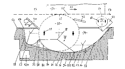
As can be seen in Figure 4, the lower part of applicator wheel
30 iS immersed in glue tank 34, which is filled with adhesive; the
height of the glue in the tank is identified by appropriate markings 52.
WO 94/22593 ~ 5~ ~2 PCT/US94/03297
- 14-
Above applicator wheel 30 and spinner roll 32, there is a book block
54 to be glued, shown in broken line. The direction in which the
block is moving is indicated by an arrow 56. In Figure 4, spinner roll
32 is shown in its lowered position, in which the distance between it
and spine 55 is greater than the distance between applicator wheel 30
and spine 55. The distance between spinner roll 32 and the spine can
be reduced, however, by means not shown. Book blocks 54 are
therefore (as shown in Figures 4 and 5) fed toward the applicator
wheel from the left and leave the area of the glue tank toward the
right. The rotational directions of applicator wheel 30 and spinner roll
32 are indicated by arrows 58, 60. Glue tank 34 has an upper
outside edge 62, which, in Figure 5, appears as a rectangle; an upper
inside edge 64, situated farther inward and somewhat lower down,
has slightly rounded corners 65. In the inside area of glue tank 34, in
the forward end with respect to the arriving book blocks 54, a nearly
vertical forward end wall 66 of glue tank 34 continues into a bottom
area, whereas, at the back end, a less steeply angled rear end wall 68
continues into the bottom area. The forward and back end walls 66,
68 are connected by two side walls 70, 72. In the transition area
between side wall 70 and end wall 68, a horizontal inlet hole 74,
coming from outside of the glue tank, has its opening; a supply line
(not shown) for introducing adhesive is connected to this inlet hole;
7122 ~ ?97
-- 1 5 -- ~ ;
the opening of this supply line has an elongated appearance, as shown in Figure 5.
A doctor blade device 78 is built into the bottom 76 of glue tank 34 near the
lower part of applicator wheel 30; this doctor blade device consists of a step 80,
approximately at the lowermost point of the wheel's peAphery and extending axially with
respect to the wheel. This step is located between a first bottom section 82 of glue tank
34 relatively far away from the peApheral surface of the wheel and a second bottom
section 84, following in the direction of rotation, relatively close to the peApheral
surface, with the result that a gap 86 is formed between applicator wheel 30 and second
bottom section 84. The step has an approximate height of 1-2 mm, and the distance
between it and the peApheral surface of applicator wheel 30 is about 5/lO mm to 7/lO
mm. Gap 86 ends at an edge 88 and is bounded on the sides by two walls 90. In the
forward area of glue tank 34, doctor blade device 78 drops down from edge 92 and
continues toward the left as forward end wall 66.
At the de~pest part of bottom 76, a vertical outlet hole 94 is provided, which can
be conn~ted to an outlet line (not shown) by means of an in~ern~l thread. A kind of
coll~tin~ basin 96 is recessed into bottom 76 near outlet hole 94. Side walls 90 are
appl~;m~t~ly hoAzontal at their highest point, starting from edge 88 and eYten-lin~
~,. .. ..
~ ~157122
WO 94/22593 PCT/US94/03297
- 16-
all the way to edge 98, and then they drop down in the rear area to
bottom section 82, ending at a crease 100 in floor 76 of glue tank
34.
As can be seen from Figure 6, electric motor 18 makes use of
an intermediate gear 102 to drive, in a manner not shown, a
countershaft 104 of transmission unit 20. At one end of countershaft
104 there is a gear wheel 106, which meshes with a gear wheel 108
on applicator wheel shaft 110. A gear wheel 112, also mounted on
applicator wheel shaft 110, engages with a pinion 114, which drives
a second countershaft 116, on which a wheel 118 is mounted, by
way of which a spinner roll shaft 122 is driven by means of a toothed
belt 120 and an additional wheel 121. Both applicator wheel 30 and
spinner roll 32 are supported in cantilever fashion.
The way in which the wheel applicator device according to the
invention functions is described in the following.
First, wheel applicator device 1 is pushed into position near a
bookbinding machine (not shown), so that applicator wheel 30 and
spinner roll 32 are underneath the conveyors and guides (not shown)
of the bookbinding machine, Then applicator wheel 30 and spinner roll
32 are adjusted in the vertical direction by turning hand crank 16 to
raise or lower the frame. The conveyors and guides convey book
blocks 54 to be glued forward at an adjustable speed; the blocks are
WO 94/22593 ~ l ~i 7 12 2 PCT/U594/03297
aligned so that the length dimension of book spines 55 is per-
pendicular to the axis of applicator wheel 30 and so that the spines
are conducted past the top apex line of the peripheral surface of
applicator wheel 30. Book spines 55 to be glued thus come into
contact with the adhesive, which was picked up in the lower part of
the glue tank and which is adhering to the peripheral surface of
applicator wheel 30; in this way the glue is transferred to book spine
55. Excess glue adhering to the spine is removed or pressed into the
intermediate spaces between the pages of the book by spinner roll 32,
which rotates in the direction opposite that of applicator wheel 30.
The peripheral velocity of applicator wheel 30 is exactly the same as
the transport speed of the book blocks, which is accomplished by the
coupling of controller device 24 to an electrical signal transmitter with
a sensor, the signal transmitter being mounted rigidly inside the
bookbinding machine in such a way that its sensor can detect the
motion of book blocks 54. As a result, a signal corresponding to the
speed of book blocks 54 is available at the output of the signal
transmitter for use by control device 24. The signal can be
transmitted by the signal transmitter in a wireless manner or by means
of a cable, which can be plugged into a jack in control device 24.
The conveyors and guides of the bookbinding machine push
book blocks 54 forward at a constant speed in such a way that spines
WO 94/22~93 ~ 2 2 PCT/US94/03297
- 18-
55 are in a horizontal plane 53. The two top apex lines 59, 61 of the
peripheral surfaces of applicator wheel 30 and spinner roll 32 are
directly adjacent to plane 53. So that the action of spinner roll 32 on
spines 55 glued by applicator wheel 30 can be varied with the goal of
changing the amount of glue applied, the distance between spinner
roll 32 and plane 53 and thus the distance between apex line 61 and
plane 53 can be adjusted by the use of means (not shown) for a
adjusting the height of spinner roll shaft 122, these means being
provided inside transmission unit 20 and comprising, for example,
pneumatic cylinders, the piston rods of which act on guide shoes,
which are supported in such a way that they can slide vertically inside
the housing wall. The bearings for spinner roll shaft 122 are installed
in these shoes. In the exemplary embodiment of drive unit 22 shown
especially in Figure 6, the speed and direction of rotation of spinner
roll 32 are coupled "rigidly" to the speed of applicator wheel 30, but it
is also possible, of course, to provide an independent drive for spinner
roll 32.
Fresh adhesive is introduced at a metered flow rate into glue
tank 34 through inlet hole 74 (Figures 4 and 5) from an adhesive
preparation device (not shown). A relatively large amount of the
adhesive supplied to the tank is subjected inside the glue tank to the
currents caused by the rotation of applicator wheel 30 and is thus
WO 94122593 PCTIUS94/03297
~571~
- 19 -
conveyed toward a narrowing gap, formed between first bottom
section 82 and a section of the peripheral surface of applicator wheel
30 opposite that part of the bottom. At step 80, comprising part of
doctor blade device 78, the adhesive arrives in gap 86 and is trans-
ported through it. By virtue of the special design of doctor blade
device 78, most of the adhesive introduced into gap 86 passes
directly through the gap and is carried from there, because of its
adherence to the peripheral surface of applicator wheel 30, past main
doctor blade 40 and onto book spines 55 to be glued. By varying the
distance between main doctor blade 40 and applicator wheel 30, it is
possible to vary the thickness of the film of adhesive adhering to
applicator wheel 30, this possibility being necessary so that the
application of adhesive can be adapted to suit the interval between
one book block 54 to be glued and the following block and also to suit
the length of spine 55. Another sensor is provided for this, which
signals the arrival of a book block above the forward area of the glue
tank.
The above-mentioned signal transmitter inside the bookbinding
machine supplies a frequency signal, also mentioned above, which is
proportional to the speed of the machine. This signal is also used as a
- distance signal for the control of main doctor blade 40. In this way, it
is po$sible to apply glue intermittently to applicator wheel 30, which
WO 94/22593 2~ 2 2 PCT/US94/03297
- 20 -
is preferred, this glue then being transferred to the spine of the book.
Main doctor blade 40 opens and closes with each book passing by the
wheel, corresponding to arrow 41 in Figure 4. The control system is
set up so that the length over which glue is applied is kept constant
no matter how the speed of forward feed may change. An
electromagnetically driven pneumatic cylinder (not shown in the
drawing for the sake of clarity) is used to move main doctor blade 40
in the direction indicated by arrow 41.
Some of the excess adhesive present in the forward area of
glue tank 34 near front end wall 66 can flow around side walls 90 to
the rear area of glue tank 34, and some of this adhesive can be
returned through outlet hole 94 to the adhesive preparation device.
Doctor blades 42, 44 also serve to wipe off excess adhesive from
applicator wheel 30 and spinner roll 32, respectively. Step 80 of
doctor blade device 78 is about 1 mm high, and a gap with a width of
about 5t10-7/10 mm is formed between it and the applicator wheel.
Applicator wheel 30, spinner roll 32, and glue tank 34 can be
heated electrically or by means of a thermal transfer fluid, if the
properties of the adhesive require it. In the case of an electric heating
system, heating wires are provided in the walls of glue tank 34, close
to the inside surface of the tank, and along and just inside the
peripheral surfaces of applicator wheel 30 and spinner roll 32. The
WO 94/22593 2 ~ ~ ~ l. 2 2 PCT/US94/03297
- 21 -
heating wires in glue tank 34 are supplied with current from an
electrical terminal 124, whereas the heating wires inside the
applicator wheel are supplied by means of carbon brushes acting on
- shaft 110 of the applicator wheel. When a thermal transfer fluid is
used to heat the adhesive, the heating wires are essentially replaced
by channels. The temperatures of the heated parts can be regulated
by means of a controller installed inside the control device. Protection
against overheating can also be provided.
Electric motor 18 is connected to a high-amperage line in a
manner not shown.
WHAT IS CLAIMED: