Language selection

Search

Patent 2157647 Summary

Third-party information liability

Some of the information on this Web page has been provided by external sources. The Government of Canada is not responsible for the accuracy, reliability or currency of the information supplied by external sources. Users wishing to rely upon this information should consult directly with the source of the information. Content provided by external sources is not subject to official languages, privacy and accessibility requirements.

Claims and Abstract availability

Any discrepancies in the text and image of the Claims and Abstract are due to differing posting times. Text of the Claims and Abstract are posted:

  • At the time the application is open to public inspection;
  • At the time of issue of the patent (grant).
(12) Patent Application: (11) CA 2157647
(54) English Title: VALVE
(54) French Title: APPAREIL DE ROBINETTERIE
Status: Deemed Abandoned and Beyond the Period of Reinstatement - Pending Response to Notice of Disregarded Communication
Bibliographic Data
(51) International Patent Classification (IPC):
  • F16K 31/126 (2006.01)
  • F15C 03/04 (2006.01)
  • F15C 05/00 (2006.01)
  • F16K 07/17 (2006.01)
(72) Inventors :
  • FARRELL, GREGORY A. (United States of America)
  • HANMANN, KEVIN J. (United States of America)
  • SCHMITZ, PETER (United States of America)
  • BEHRINGER, BRUCE E. (United States of America)
  • MAWHIRT, JAMES A. (United States of America)
(73) Owners :
  • BAYER CORPORATION
(71) Applicants :
  • BAYER CORPORATION (United States of America)
(74) Agent: MACRAE & CO.
(74) Associate agent:
(45) Issued:
(22) Filed Date: 1995-09-06
(41) Open to Public Inspection: 1996-04-08
Examination requested: 2002-06-12
Availability of licence: N/A
Dedicated to the Public: N/A
(25) Language of filing: English

Patent Cooperation Treaty (PCT): No

(30) Application Priority Data:
Application No. Country/Territory Date
08/319,918 (United States of America) 1994-10-07

Abstracts

English Abstract


A valve comprises a first rigid layer having a
substantially planar first surface, a second rigid layer
having a substantially planar second surface facing the
first surface and a substantially planar third surface
opposite the second surface and a flexible layer positioned
between the first and second surfaces. A valve chamber is
demarcated by a concave surface in the substantially planar
first surface and one surface of the flexible layer and at
least one first fluid passageway in the first rigid layer
opens into the valve chamber at the concave surface to
alternatively apply a vacuum and pressure thereto. A fluid
chamber is demarcated by another surface of the flexible
layer and a concave-convex surface in the substantially
planar second surface which comprises an inner circular
convex portion and a concentric annular outer concave
portion. At least two second fluid passageways in the
second rigid layer open into the valve chamber at the convex
surface. When a vacuum is applied to the valve chamber, the
flexible layer flexes to space the other surface of the
flexible layer apart from the concave-convex surface to
permit communication between the at least two second fluid
passageways and when a pressure is applied to the valve
chamber, the flexible layer flexes to dispose the other
surface of the flexible layer on the concave-convex surface

to prevent communication between the at least two second
fluid passageways.


Claims

Note: Claims are shown in the official language in which they were submitted.

What is claimed is:
1. A valve comprising:
a first rigid layer having a substantially planar first
surface;
a second rigid layer having a substantially planar
second surface facing the first surface and a substantially
planar third surface opposite the second surface;
a flexible layer positioned between the first and
second surfaces;
a valve chamber demarcated by a concave surface in the
substantially planar first surface and one surface of the
flexible layer;
at least one first fluid passageway in the first rigid
layer opening into the valve chamber at the concave surface
to alternatively apply a vacuum and pressure thereto;
a fluid chamber demarcated by another surface of the
flexible layer and a concave-convex surface in the
substantially planar second surface and comprising an inner
circular convex portion and a concentric annular outer
concave portion; and
at least two second fluid passageways in the second
rigid layer opening into the valve chamber at the convex
surface;
whereby when a vacuum is applied to the valve chamber
the flexible layer flexes to space the other surface of the
flexible layer apart from the concave-convex surface to

permit communication between the at least two second fluid
passageways and when a pressure is applied to the valve
chamber the flexible layer flexes to dispose the other
surface of the flexible layer on the concave-convex surface
to prevent communication between the at least two second
fluid passageways.
2. The valve according to claim 1, wherein the
concave surface in the first surface and the convex portion
of the concave-convex surface have common center points.
3. The valve according to claim 1, further
comprising a compression-expansion relief annulus in the
first substantially planar surface surrounding the concave
surface and a compression-expansion relief channel in the
second substantially planar surface surrounding the concave-
convex surface and around the relief annulus to form a
compression zone therebetween.
4. The valve according to claim 3, further
comprising means connecting the first and second rigid
layers with the flexible layer therebetween, whereby a
portion of the flexible layer in the compression zone
effects a sealing of the fluid and valve chambers.
11

5. The valve according to claim 1, further
comprising a third rigid layer having a substantially planar
fourth surface facing the third surface.
6. The valve according to claim 5, further
comprising means connecting the second and third rigid
layers with the third and fourth surfaces adjacent each
other.
7. The valve according to claim 6, wherein the
at least two second fluid passageways each comprise a
channel in the third and fourth surfaces which are aligned
when the second and third rigid layers are connected.
8. The valve according to claim 7, wherein the
means connecting the second and third rigid layers comprises
means forming a seal around the channels in the third and
fourth surfaces.
9. The valve according to claim 8, wherein the
first, second and third rigid layers comprise acrylic
plastic.
10. The valve according to claim 9, wherein the
means forming a seal comprises means forming a diffusion
bond.
12

11. The valve according to claim 1, wherein the
convex portion of the concave-convex surface has a center
point which is coplanar with the first surface.
13

Description

Note: Descriptions are shown in the official language in which they were submitted.


2l5~6~7
I
BAC~GROUND OF THE 1NV~N lON
The present invention relates to a valve assembly
and in particular, a fluid valve with an elastomeric
diaphragm.
Fluid valves of this type are known in the art, as
can be seen for example in U.S.P. 4,852,851.
Early valves had a non-elastic diaphragm which
necessitated equal deforma~ions between open and closed
positions.
In later prior art valves of this type, because of
the geometry of the fluid and valve chambers formed therein,
the flexible sheet member wrinkled and puckered as a result
of the unequal deformations between the open and closed
position of the valve, resulting in unreliable valve
function due to improper sealing.
S~MMARY OF THE lNV~NllON
The main object of the present invention is to
provide a valve which eliminates the disadvantages of prior
art valves. The present invention provides higher sealing
pressure, low dead volume, low carryover, long life,
chemical compatibility and dense packaging.
Another object of the present invention is to
provide a valve which alternately stops or allows the flow
of a liquid or air through an acrylic or other manifold
conduit which is fused or otherwise sealed. The fluid being

21~7647
controlled is isolated by an elastic diaphragm from the
pressure/vacuum solenoid valve or mechanism.
A further object of the present invention is to
provide a high density miniature valve with a small dead
volume to provide a diaphragm configuration that permits
equal deformation in both open and closed states.
These and other objects and advantages of the
present invention are achieved in accordance with the
present invention by a valve comprising a first rigid layer
having a substantially planar first surface, a second rigid
layer having a substantially planar second surface facing
the first surface and a substantially planar third surface
opposite the second surface, a flexible layer positioned
between the first and second surfaces, a valve chamber
demarcated by a concave surface in the substantially planar
first surface and one surface of the flexible layer, a first
fluid passageway in the first rigid layer opening into the
fluid chamber at the concave surface to alternatively apply
a vacuum and pressure thereto, a fluid chamber demarcated by
the other surface of the flexible layer and a concave-convex
surface in the substantially planar second surface. The
concave-convex surface comprises an inner circular convex
portion and a concentric annular outer concave portion. Two
fluid passageways in the second rigid layer open into the
valve chamber at the convex surface.

2~7647
When a vacuum is applied to the valve chamber, the
flexible layer flexes to space the other surface thereof
apart from the concave-convex surface to permit
communication between the two second fluid passageways.
When a pressure is applied to the valve chamber, the
flexible layer flexes to dispose the other surface of the
flexible layer on the concave-convex surface to prevent
communication between the two fluid passageways.
The valve also includes a third rigid layer having
a substantially planar fourth surface facing the third
surface. The two second fluid passageways comprise a
channel in the third and fourth surfaces which are aligned
when the second and third rigid layers are connected.
In this way, the fluid pathway is located in a
plane which is displaced from the plane of the flexible
layer. The concave-convex surface is a combination of
shapes that provides for equal elastomer stretch deformation
in both the open and closed positions, with positive closure
in the closed position by providing a "positive wrap" around
the shut passages.
The valve also contains an annulus which fully
contains the extruded diaphragm material due to the
perimeter compression required to seal the valve,
eliminating compromising the elastic diaphragm performance
and perimeter deformability.

21576~
The rigid layers are preferably acrylic plastic
material which are preferably clear. The layers are
preferably connected by diffusion, adhesive or solvent
bonding as set forth in U.S.P. 4,875,956, the disclosure of
which is hereby incorporated by reference. The layers can
also be connected mechanically by fasteners such as bolts or
screws.
The valve in accordance with the present invention
is preferably used in unified fluid circuits for clinical
diagnostic analyzers for hematology, chemistry, chemical and
immunology.
These and other features and advantages of the
present invention will be described in more detail with
reference to the attached drawings wherein:
BRIEF DESCRIPTION OF THE DRAWINGS
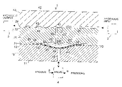
Fig. 1 is a sectional view of a valve according to
the present invention; and
Fig. 2 is an exploded view of the valve of Fig. 1.
DETAILED DESCRIPTION OF THE INVENTION
Referring now to Figs. 1 and 2, the valve 1
comprises a first rigid layer 10 having substantially planar
surfaces 11 and 12, a second rigid layer 20 having
substantially planar surface 21 and 22 and a third rigid
layer 40 having substantially planar surfaces 41 and 42.

1 ~157647
Disposed between surfaces 12 and 21 is a flexible layer 30
of elastomeric material such as rubber.
The valve further includes a valve chamber
demarcated by a concave surface 14 in the planar surface 12
and by one surface 31 of the flexible layer 30. At least
one fluid passageway 15 in the first rigid layer 10 opens
into the valve chamber at the concave surface 14 and the
fluid passageway 15 is connected to a valve 4 which
alternately applies vacuum 5 or pressure 6 to the valve
chamber.
The valve also includes a fluid chamber demarcated
by the surface 32 of the flexible layer 30 and a concave-
convex surface in the surface 21 comprising an inner
circular convex portion 24 and a concentric annular outer
concave portion 25.
The convex portion 24 preferably has a dome point
at the center thereof and the tangent thereto is coplanar
with the surface 21 of rigid layer 20. That dome point is
aligned with the center of the concave surface 14.
Surface 12 also includes a compression-expansion
relief annulus 13 which surrounds the concave surface 14.
Surface 21 includes a compression-expansion relief channel
23 which surrounds the annulus 13 and the concave-convex
surface and defines a compression zone 33 between the
annulus 13 and the channel 23. The compression zone
compresses the flexible layer 30 and the channel 23 provides

21~547
,
for extruded diaphragm material. When the rigid layers 10
and 20 are connected together as shown in Fig. 1, the
compression zone 33 acts to seal the periphery of the valve
and fluid chambers.
The rigid layer 20 includes two fluid passageways
26 and 27 which open into the fluid chamber at the convex
portion 24 and extend to the surface 22 thereof.
The rigid layer 20 has channel 44 formed in the
surface 22 thereof and the rigid layer 40 has channel 43 in
the surface thereof which is aligned with channel 4-4 to form
fluid conduit 28. Fluid conduit 29 is formed in the surface
41 of layer 40. The surfaces 41 and 22 are bonded together
by diffusion bonding in order to seal the passageways 28 and
29.
Channel 29 is in communication with passageway 27
and hydraulic input 2 and channel 28 is in communication
with passageway 26 and hydraulic output 3.
In operation, when vacuum 5 is applied to the
valve chamber through passageway 15, the flexible layer
flexes into position P1 so that surface 32 is spaced apart
from the convex portion 24 and the fluid chamber is open
permitting communication between the hydraulic input 2 and
the hydraulic output 3 via passageways 29, 27, 26 and 28.
When pressure 6 is applied to the valve chamber,
the flexible layer 30 flexes into the closed position P2 so
that the surface 32 is tightly against the convex and

2~7647
concave surfaces 24 and 25 preventing communication between
the hydraulic input 2 and the hydraulic output 3.
As a result of the concave-convex surface, there
will be equal elastomer stretch deformation in both the open
and closed positions P1 and P2.
In one embodiment of the present invention, the
rigid layers are composed of fully normalized clear cast
acrylic and the flexible layer is composed of silicone
sheeting. Each of the rigid layers are about 0.10" to 0. 25 "
thick and the flexible layer is about 0.01" thick and has a
diameter of about 0.375". Channel 23 has an inner diameter
of 0. 322 " and an outer diameter of 0. 4 " and a height of
0.012". Annulus 13 has a diameter of 0. 225 " and steps down
0 . 005" from surface 12. Compression zone 33 has an inner
diameter of 0.225" and an outer diameter of 0.322" and the
surface 21 is stepped down by 0.009" in the compression
zone.
Passageway 15 has a diameter of 0.031" and
passageways 26 and 27 have a diameter of 0.02" and a center
to center spacing of 0. 05" . Concave surface 31 has a
diameter of 0.156 ", a spherical radius of 0.1" and a depth
of o. 025 " . Convex portion 24 has an outer diameter of
0 .156 ", an inner diameter of 0. 06 " and a radius of curvature
of 0.02". Concave portion 24 has a diameter of 0. 06 " and a
spherical radius of 0.08".

,~ 2157~47
It is understood that the embodiments described
hereinabove are merely illustrative and are not intended to
limit the scope of the invention. It is realized that
various changes, alterations, rearrangements and
modifications can be made by those skilled in the art
without substantially departing from the spirit and scope of
the present invention.

Representative Drawing
A single figure which represents the drawing illustrating the invention.
Administrative Status

2024-08-01:As part of the Next Generation Patents (NGP) transition, the Canadian Patents Database (CPD) now contains a more detailed Event History, which replicates the Event Log of our new back-office solution.

Please note that "Inactive:" events refers to events no longer in use in our new back-office solution.

For a clearer understanding of the status of the application/patent presented on this page, the site Disclaimer , as well as the definitions for Patent , Event History , Maintenance Fee  and Payment History  should be consulted.

Event History

Description Date
Inactive: IPC from MCD 2006-03-11
Time Limit for Reversal Expired 2004-09-07
Application Not Reinstated by Deadline 2004-09-07
Deemed Abandoned - Failure to Respond to Maintenance Fee Notice 2003-09-08
Letter Sent 2002-06-28
Inactive: Status info is complete as of Log entry date 2002-06-28
Inactive: Application prosecuted on TS as of Log entry date 2002-06-28
Request for Examination Requirements Determined Compliant 2002-06-12
All Requirements for Examination Determined Compliant 2002-06-12
Application Published (Open to Public Inspection) 1996-04-08

Abandonment History

Abandonment Date Reason Reinstatement Date
2003-09-08

Maintenance Fee

The last payment was received on 2002-08-21

Note : If the full payment has not been received on or before the date indicated, a further fee may be required which may be one of the following

  • the reinstatement fee;
  • the late payment fee; or
  • additional fee to reverse deemed expiry.

Patent fees are adjusted on the 1st of January every year. The amounts above are the current amounts if received by December 31 of the current year.
Please refer to the CIPO Patent Fees web page to see all current fee amounts.

Fee History

Fee Type Anniversary Year Due Date Paid Date
MF (application, 2nd anniv.) - standard 02 1997-09-08 1997-08-22
MF (application, 3rd anniv.) - standard 03 1998-09-08 1998-08-20
MF (application, 4th anniv.) - standard 04 1999-09-06 1999-08-25
MF (application, 5th anniv.) - standard 05 2000-09-06 2000-08-29
MF (application, 6th anniv.) - standard 06 2001-09-06 2001-08-24
Request for examination - standard 2002-06-12
MF (application, 7th anniv.) - standard 07 2002-09-06 2002-08-21
Owners on Record

Note: Records showing the ownership history in alphabetical order.

Current Owners on Record
BAYER CORPORATION
Past Owners on Record
BRUCE E. BEHRINGER
GREGORY A. FARRELL
JAMES A. MAWHIRT
KEVIN J. HANMANN
PETER SCHMITZ
Past Owners that do not appear in the "Owners on Record" listing will appear in other documentation within the application.
Documents

To view selected files, please enter reCAPTCHA code :


To view images, click a link in the Document Description column. To download the documents, select one or more checkboxes in the first column and then click the "Download Selected in PDF format (Zip Archive)" or the "Download Selected as Single PDF" button.

List of published and non-published patent-specific documents on the CPD .

If you have any difficulty accessing content, you can call the Client Service Centre at 1-866-997-1936 or send them an e-mail at CIPO Client Service Centre.


Document
Description 
Date
(yyyy-mm-dd) 
Number of pages   Size of Image (KB) 
Representative drawing 1999-06-24 1 24
Description 1995-09-05 8 264
Abstract 1995-09-05 2 43
Claims 1995-09-05 4 97
Drawings 1995-09-05 2 47
Representative drawing 2004-02-24 1 19
Reminder - Request for Examination 2002-05-06 1 118
Acknowledgement of Request for Examination 2002-06-27 1 193
Courtesy - Abandonment Letter (Maintenance Fee) 2003-11-02 1 176
Fees 1996-03-13 1 24