Language selection

Search

Patent 2158311 Summary

Third-party information liability

Some of the information on this Web page has been provided by external sources. The Government of Canada is not responsible for the accuracy, reliability or currency of the information supplied by external sources. Users wishing to rely upon this information should consult directly with the source of the information. Content provided by external sources is not subject to official languages, privacy and accessibility requirements.

Claims and Abstract availability

Any discrepancies in the text and image of the Claims and Abstract are due to differing posting times. Text of the Claims and Abstract are posted:

  • At the time the application is open to public inspection;
  • At the time of issue of the patent (grant).
(12) Patent: (11) CA 2158311
(54) English Title: CHEESE SLICER
(54) French Title: TRANCHE-FROMAGE
Status: Deemed expired
Bibliographic Data
(51) International Patent Classification (IPC):
  • B26B 13/00 (2006.01)
  • B26B 29/06 (2006.01)
  • B26D 1/00 (2006.01)
  • B26D 1/08 (2006.01)
(72) Inventors :
  • HOLCOMB, DAVID (United States of America)
  • LARSEN, BRADLEY BURTON (United States of America)
(73) Owners :
  • CHEF'N CORPORATION (United States of America)
(71) Applicants :
  • CHEF'N CORPORATION (United States of America)
(74) Agent: OYEN WIGGS GREEN & MUTALA LLP
(74) Associate agent:
(45) Issued: 2007-09-11
(22) Filed Date: 1995-09-15
(41) Open to Public Inspection: 1996-03-17
Examination requested: 2002-08-23
Availability of licence: N/A
(25) Language of filing: English

Patent Cooperation Treaty (PCT): No

(30) Application Priority Data:
Application No. Country/Territory Date
08/307,876 United States of America 1994-09-16

Abstracts

English Abstract

A cheese slicer having a flat base and a blade holder releasably pivotally secured to the base for moving from a locked upright cheese slicing position to a lowered storing position. A unique wide, flat blade slidably carried in the blade holder and having an upper end with a large handle and a lower end. The lower end having a downwardly and rearwardly sloping separating surface terminating in a downwardly protruding blunt slicing edge.


French Abstract

Un tranche-fromage doté d'une base plate et d'un porte-lame pivotant rétractable fixé à la base pour se déplacer à partir de la position verrouillée de tranchage du fromage à la position couchée pour le rangement. La lame, droite et large, se glisse dans le porte-lame et est munie d'une extrémité supérieure dotée d'une grande poignée et d'une extrémité inférieure. L'extrémité inférieure est pourvue d'une surface de séparation courbée vers le bas et l'arrière qui se termine par une extrémité tranchante protubérante.

Claims

Note: Claims are shown in the official language in which they were submitted.


Claims


1.A slicing blade for cutting slices from a block of soft food product, the
blade having a flat
blade body (14) of uniform thickness and having upper and lower blade ends
(31, 32), a
forward side facing a cut slice of soft food product, and a rearward side
facing the block
of soft food product (c), said lower blade end having a downwardly and
rearwardly
sloping separating surface (34), terminating in a downwardly protruding
slicing surface
offset rearwardly from said rearward side beyond any other blade surface,
being substan-
tially parallel to said rearward side, and terminating at a terminal edge
(36), the slicing
surface being offset rearwardly from the rearward side of the blade body to
provide a
minimal contact surface with the soft food product to be sliced to reduce
friction between
the block of soft food product and the blade body.


2.The slicing blade of claim 1, said terminal edge having a blunt lower
surface.


3.The slicing blade of claim 1, including a flat handle (31) separable from
the blade body
and attached to and overlying substantially the upper end of the blade body
(14).


4.The slicing blade of claim 1, said blade body adapted to be guided in a
blade holder (12)
having guide grooves, said blade body being of a uniform thickness and having
opposite
guide areas along the forward and rearward sides, and said guide areas adapted
to move in
guide grooves of said blade holder for guiding the blade body during slicing.


5.The slicing blade of claim 1, wherein the downwardly protruding slicing
surface is a
straight surface across the lower blade end of the blade body.


6.A device for slicing a food product, said device comprising

a base for supporting a block of said food product;


a blade holder having an upright position at one end of said base, said blade
holder having
opposed parallel grooves; and


a unitary blade of uniform thickness, said blade comprising


a single flat upper major portion having parallel lateral edges slidingly
retained in said
grooves so that the blade can move through a cutting stroke between an upper
position in
which the blade is spaced apart from the base and a lower position in which
the blade is at
least proximate the base,


a lower minor portion substantially parallel to said upper major portion, said
lower minor
portion being offset from said upper major portion in a direction toward a
portion of the


6

base upon which the block of food product is intended to rest, and terminating
at a cutting
edge, the motion of the cutting edge through the cutting stroke defining a
cutting plane
and no other part of the blade ever being in said cutting plane, and


an intermediate portion extending at an angle between said lower minor portion
and said
upper major portion, whereby said upper major portion is kept out of contact
with said
food product, said minor portion cuts the food product, and the intermediate
portion
deflects cut slices away from the base.


7.The device of claim 6, further comprising a handle extending along an upper
edge of said
upper major portion whereby one can drive the blade from its upper position to
its lower
position by pressing on the handle.


8.The device of claim 6, wherein the cutting edge of the blade is blunt.


9.The device of claim 6, wherein the cutting edge of the blade is a straight
edge.

Description

Note: Descriptions are shown in the official language in which they were submitted.


1
Description

CHEESE SLICER
Technical Field
This invention relates generally to slicers for
slicing soft food products, such as cheese, butter, pate'
and the like.

Background of the Invention
There is a need for a cheese slicer of the type
capable of cutting smoothly a slice of cheese from a block
of cheese. Heretofore cheese cutters have used knife
blades or wires. An example of a wire cheese slicer is
shown in patent 4,960,024. An example of a cutting blade
is shown in patent 2,570,671.
These cheese slicers, however, have been
somewhat awkward to handle or create storage problems.

Summary of the Invention
It is an object of this invention to provide an
improved cheese slicer having a wide, flat blade and a
blade holder which can be pivoted from an upright slicing
position to a folded collapsible position for storage.
It is another object of this invention to
provide a cheese slicer where the slicing blade is easily
removed for cleaning.
Still another object of this invention is to
provide a cheese slicing blade having a wide, flat body
with a lower end which smoothly separates the slice of
cheese from the block of cheese.
Basically, these objects are achieved by having
a flat base with a pivotally mounted cheese slicing blade
holder on the base. The blade holder is provided with
opposed slots which receive a large flat, wide slicing
blade. Detents hold the blade holder in its upright
slicing position. The blade has an upper end with a large


2158311
2

flat handle and a lower end with a downwardly and
rearwardly sloping separating surface. The separating
surface terminates downwardly along a plane parallel to
the flat, wide slicing blade and terminates into a blunt
edge of a shape roughly equivalent to a cheese slicing
wire.
With this invention, the slicing of cheese is
done very quickly with smooth separation of the slices
from the block of cheese. For storage, the blade holder
folds down to a compact position taking much less space
that in its upright position.

Brief Description of the Figures of the Drawings
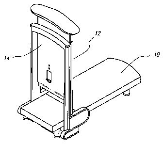
Figure 1 is an isometric of the cheese slicer
with the blade holder in an upright position.
Figure 2 is a schematic illustration showing the
blade separating a slice of cheese from a block of cheese.
Figure 3 is a side elevation of the cheese
slicer.
Figure 4 is a fragmentary front elevation of the
cheese slicer with parts broken away for clarity.
Figure 5 is a bottom view of the cheese slicer.
Detailed Description of the Embodiments
As best shown in Figure 1, the cheese slicer has
a flat base 10, an upright blade holder 12, a wide, flat
blade 14 slidably secured in the blade holder.
The flat base 10 is a rigid plastic member
having support legs 16. Rubber cushioning pads 18 are
connected to each of the four support legs. The blade
holder 12 is pivotally mounted to the forward end of the
base by pivot pins 20. Thus, the blade holder can move
from the upright position shown in Figure 3 to the phantom
line storage position shown in Figure 3.
The blade holder is held in its upright position
by spring biased detent pins 22 which are received in
recesses 24. As best shown in Figure 5 the pins are


CA 02158311 2005-10-07
3

pushed into the recesses by a spring 26 having finger
grips 28. The lower ends of the blade holder are also
provided with ramps 30 which slide over the detent pins
compressing them until the pins are beyond the ramps and
are pushed outwardly into the recesses 24 by the spring 26
Thus, the blade holder is automatically locked into its
upright position when it is raised. To release the pins,
the finger grips 28 are compressed toward one another
which withdraws the detent pins from the recesses allowing
the blade holder to be moved to the storage folded
position.
As best shown in Figures 2 and 4, the slicing
blade 14 is a large wide, thin flat body having an upper
end 31 and a lower end 32. The upper end has a large flat
smooth handle 34 attached thereto so that the palm of the
hand can be used for pushing the slicing blade through the
cheese C.
The lower end of the slicing blade is provided
with a rearwardly, downwardly sloped separating surface 34
that terminates in a lower slicing edge 36. The thickness
of the blade at the slicing edge is about 0.80mm and is
blunt like a cheese slicing wire rather than provided with
a sharp edge. The height "hl' is kept to a minimum and is
approximately 3/16 of an inch. This reduces the friction
against the cheese during cutting making movement of the
slicing blade through the cheese easier. The sloping
surface allows the front upper edge of the sloping surface
where it bends into the cutting blade to gently push a
slice of cheese away, allowing for easy separation of the
cheese and again minimizing friction between the cutting
blade and the block of cheese.
The slicing blade is guided in the blade holder
in a pair of opposed grooves 40. The upper end of the
blade holder has a cross bar 42 on the forward side of the
holder only. The blade is provided with a central spring
biased pawl 46 that can be flexed rearwardly. The panel
has an upper ledge 48 which will engage the support bar 42


4
when the handle is raised to slice another slice of
cheese. To remove the blade for cleaning, however, the
pawl can be pushed rearwardly until the ledge 48 is clear
of the support bar 42 and the blade can be slid free of
the blade holder.
In operation the blade holder is swung up to its
upright position with the detent pins automatically being
compressed by the ramps and then falling into the recesses
for holding the blade holder securely in the upright
position. The blade is raised and the block of cheese
placed on the base and slid forward one slice thickness.
The operator then places a hand on the handle pushing the
blade through the forward end of the block of cheese with
the separating edge slicing the cheese and separating it
from the block of cheese. The lower cutting edge 36 of
the cheese jogs down from the separating surface and is
approximately parallel to the plane of the slicing blade
and provides only a minimum height for low friction
engagement with the block of cheese making the slicing of
the cheese very easy for the operator. If the operator
wishes to wash the blade, it is only necessary to depress
the pawl 46 and lift the blade free of the blade holder.
Furthermore, for storage, it is only necessary to compress
the spring 26 by placing the finger and thumb in the
finger grips 28 and retracting the detent pins from their
recesses. This allows the blade holder to pivot
downwardly and rest smoothly against the base for a
minimum storage dimension.
As is apparent, the invention is capable of
modification and those skilled in the art will understand
the principles from the disclosure herein. Accordingly,
the invention is not to be limited to the specific
embodiment illustrated in the drawings.

Representative Drawing
A single figure which represents the drawing illustrating the invention.
Administrative Status

For a clearer understanding of the status of the application/patent presented on this page, the site Disclaimer , as well as the definitions for Patent , Administrative Status , Maintenance Fee  and Payment History  should be consulted.

Administrative Status

Title Date
Forecasted Issue Date 2007-09-11
(22) Filed 1995-09-15
(41) Open to Public Inspection 1996-03-17
Examination Requested 2002-08-23
(45) Issued 2007-09-11
Deemed Expired 2013-09-17

Abandonment History

There is no abandonment history.

Payment History

Fee Type Anniversary Year Due Date Amount Paid Paid Date
Application Fee $0.00 1995-09-15
Registration of a document - section 124 $0.00 1995-12-07
Maintenance Fee - Application - New Act 2 1997-09-15 $50.00 1997-09-12
Maintenance Fee - Application - New Act 3 1998-09-15 $50.00 1998-08-28
Maintenance Fee - Application - New Act 4 1999-09-15 $50.00 1999-09-07
Maintenance Fee - Application - New Act 5 2000-09-15 $75.00 2000-08-30
Maintenance Fee - Application - New Act 6 2001-09-17 $75.00 2001-08-24
Maintenance Fee - Application - New Act 7 2002-09-16 $75.00 2002-08-21
Request for Examination $200.00 2002-08-23
Maintenance Fee - Application - New Act 8 2003-09-15 $75.00 2003-08-25
Maintenance Fee - Application - New Act 9 2004-09-15 $100.00 2004-08-23
Maintenance Fee - Application - New Act 10 2005-09-15 $125.00 2005-08-19
Maintenance Fee - Application - New Act 11 2006-09-15 $250.00 2006-08-18
Expired 2019 - Corrective payment/Section 78.6 $1,025.00 2007-01-15
Final Fee $300.00 2007-06-20
Maintenance Fee - Application - New Act 12 2007-09-17 $250.00 2007-08-20
Maintenance Fee - Patent - New Act 13 2008-09-15 $250.00 2008-08-18
Maintenance Fee - Patent - New Act 14 2009-09-15 $250.00 2009-08-19
Maintenance Fee - Patent - New Act 15 2010-09-15 $450.00 2010-08-30
Maintenance Fee - Patent - New Act 16 2011-09-15 $450.00 2011-08-30
Owners on Record

Note: Records showing the ownership history in alphabetical order.

Current Owners on Record
CHEF'N CORPORATION
Past Owners on Record
HOLCOMB, DAVID
LARSEN, BRADLEY BURTON
Past Owners that do not appear in the "Owners on Record" listing will appear in other documentation within the application.
Documents

To view selected files, please enter reCAPTCHA code :


To view images, click a link in the Document Description column. To download the documents, select one or more checkboxes in the first column and then click the "Download Selected in PDF format (Zip Archive)" or the "Download Selected as Single PDF" button.

List of published and non-published patent-specific documents on the CPD .

If you have any difficulty accessing content, you can call the Client Service Centre at 1-866-997-1936 or send them an e-mail at CIPO Client Service Centre.


Document
Description 
Date
(yyyy-mm-dd) 
Number of pages   Size of Image (KB) 
Cover Page 1995-09-15 1 16
Abstract 1995-09-15 1 14
Representative Drawing 1998-03-09 1 8
Description 2005-10-07 4 182
Claims 2005-10-07 2 68
Representative Drawing 2007-01-23 1 8
Description 1995-09-15 4 182
Claims 1995-09-15 2 63
Drawings 1995-09-15 3 41
Claims 2006-07-28 2 77
Cover Page 2007-08-10 1 34
Assignment 1995-09-14 13 548
Prosecution-Amendment 2002-08-23 1 52
Prosecution-Amendment 2005-10-07 6 220
Prosecution-Amendment 2007-01-15 2 62
Prosecution-Amendment 2005-04-07 3 107
Correspondence 2006-06-12 1 11
Prosecution-Amendment 2006-02-20 3 82
Prosecution-Amendment 2006-07-28 7 241
Correspondence 2007-01-29 1 14
Correspondence 2007-06-20 1 33