Language selection

Search

Patent 2158699 Summary

Third-party information liability

Some of the information on this Web page has been provided by external sources. The Government of Canada is not responsible for the accuracy, reliability or currency of the information supplied by external sources. Users wishing to rely upon this information should consult directly with the source of the information. Content provided by external sources is not subject to official languages, privacy and accessibility requirements.

Claims and Abstract availability

Any discrepancies in the text and image of the Claims and Abstract are due to differing posting times. Text of the Claims and Abstract are posted:

  • At the time the application is open to public inspection;
  • At the time of issue of the patent (grant).
(12) Patent Application: (11) CA 2158699
(54) English Title: MULTIPART ROLL STAND
(54) French Title: DEVIDOIR A PARTIES MULTIPLES
Status: Deemed Abandoned and Beyond the Period of Reinstatement - Pending Response to Notice of Disregarded Communication
Bibliographic Data
(51) International Patent Classification (IPC):
  • B22D 11/06 (2006.01)
  • B21B 13/10 (2006.01)
  • B21B 31/02 (2006.01)
  • B21B 31/04 (2006.01)
(72) Inventors :
  • MINNEROP, MICHAEL (Germany)
  • ALBEDYHL, MANFRED (Germany)
  • SCHMIDT, KARL OTTO (Germany)
  • BAHR, HERMANN (Germany)
  • FOERMER, EGON (Germany)
  • SCHULZE, BERTHOLD (Germany)
  • SVAGR, ALEXANDER (Germany)
(73) Owners :
  • SMS SCHLOEMANN-SIEMAG AKTIENGESELLSCHAFT
(71) Applicants :
  • SMS SCHLOEMANN-SIEMAG AKTIENGESELLSCHAFT (Germany)
(74) Agent: RICHES, MCKENZIE & HERBERT LLP
(74) Associate agent:
(45) Issued:
(22) Filed Date: 1995-09-20
(41) Open to Public Inspection: 1996-03-24
Availability of licence: N/A
Dedicated to the Public: N/A
(25) Language of filing: English

Patent Cooperation Treaty (PCT): No

(30) Application Priority Data:
Application No. Country/Territory Date
G 94 15 429.5 (Germany) 1994-09-23

Abstracts

English Abstract


A continuous casting plant for casting thin slabs includes an
electromagnetic decelerating unit for the molten steel which flows
into the mold through a submerged casting pipe. The
electromagnetic decelerating unit is composed of a coil with a
ferromagnetic core arranged on each of the long sides of the mold
and a yoke surrounding the mold. The cores on the long sides of
the mold each are composed of a principal core and a partial core
on the side of the cast strand, wherein different partial cores can
be used as desired for adapting the magnetic field to changing
casting conditions.


Claims

Note: Claims are shown in the official language in which they were submitted.

We claim:
1. A multipart roll stand comprising, for forming a universal
roll stand, a vertical housing comprising a pair of independent
side pieces each having a top and a bottom, transverse girders for
connecting the side pieces at the top and bottom thereof, and tie
rods for connecting the transverse girders, each side piece having
horizontal, lateral support projections, the support projections
comprising support pieces, the support pieces defining recesses,
further comprising independent crossheads insertable in the
recesses.
2. The multipart roll stand according to Claim 1, wherein
each side piece of the vertical housing comprises two independent
side piece halves, the side piece halves being symmetrical with
respect to a vertical plane of symmetry extending through a middle
of the vertical housing, further comprising means for connecting
the side piece halves.
3. The multipart roll stand according to Claim 2, wherein
the means for connecting the side piece halves comprise projections
of the side piece halves and shrink rings placed on the
projections.

4. The multipart roll stand according to Claim 1, wherein
the means for connecting the side piece halves are additional tie
rods.
5. The multipart roll stand according to Claim 1, wherein
the recesses comprise dovetail-shaped guide means for the
crossheads.
11

Description

Note: Descriptions are shown in the official language in which they were submitted.


215869$
R~ ROUND OF THE lNv~--lON
1. Field of the Invention
The present invention relates to a multipart roll stand whose
housings can be connected to one another by tie rods or the like.
2. Description of the Related Art
Various different embodiments of multipart roll stands for
sets of rolls whose roll axes extend parallel to one another are
known in the art.
It has also already been suggested in DE-OS 27 03 252, to put
together machine frames by combining prismatic bodies whose wall
surfaces extend at a right angle to each other and then to screw
these bodies together.
A special type of roll stand, namely, the universal roll
stands which have sets of rolls whose roll axes extend vertically
and parallel to each other in addition to sets of rolls whose roll
axes extend horizontally and parallel to one another, have in the
past always been cast in one piece; this is the case because the
sets of rolls with vertically extending roll axes must be supported

21~i8~9~
by outwardly cantilevering support projections laterally of the
vertical housings.
This embodiment of the universal roll stands not only requires
a complicated casting procedure with frequently occurring casting
defects; in addition, in these universal roll stands, the cast
piece itself also requires complicated finishing, because the cast
piece must be frequently rechucked for producing the necessary
bores and finishing the guide surfaces. Moreover, several guide
surfaces are not easily accessible for processing and require the
use of complicated devises. Particularly in the case of large and
heavy stands, this type of universal roll stands has the
disadvantage that the transport of roll stands from the place of
manufacture to the place of use is cumbersome.

- ~158639
SUMMARY OF THE lNv~ ON
Therefore, it is the primary object of the present invention
to reduce the high technical requirements of manufacturing the
stands and also to simplify the possibility of transporting these
stands.
In accordance with the present invention, for forming a
universal roll stand, the vertical housing is composed of a pair of
independent side pieces which can be connected at the top and at
the bottom by transverse girders with the use of tie rods. Each
side piece has horizontal, lateral support projections with support
pieces, wherein the support pieces are provided with recesses, and
wherein independent crossheads can be inserted in the recesses.
The configuration according to the present invention makes it
possible to cast, finish and also transport the two side pieces of
the stand independently of each other in the form of relatively
flat bodies. The same is true for the transverse girders and the
crossheads.
In accordance with another feature of the present invention,
the side pieces forming the vertical housing can also be composed
of two independent side piece halves which are symmetrical with

215869~
. ~
respect to a vertical axis of symmetry, wherein the side piece
halves can be connected by means of shrink rings placed on
projections or means of tie rods. This configuration simplifies
casting, finishing and the transport of the individual components.
The various features of novelty which characterize the
invention are pointed out with particularity in the claims annexed
to and forming a part of the disclosure. For a better
understanding of the invention, its operating advantages, specific
objects attained by its use, reference should be had to the drawing
and descriptive matter in which there are illustrated and described
preferred embodiments of the invention.

-- 215869g
BRIEF DESCRIPTION OF THE DRAWING
In the drawing:
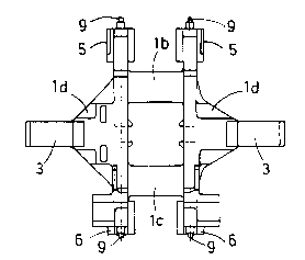
Fig. 1 is an exploded view of the components of the universal
roll stand seen in the direction of rolling;
Fig. 2 is a top view of the universal roll stand of Fig. l;
Fig. 3 is a side view of the universal roll~stand of Fig. l;
Figs. 4 - 6 are views corresponding to Figs. 1 - 3 showing the
assembled universal roll stand;
Fig. 7 is an exploded view showing the components of another
embodiment of the universal roll stand according to the present
invention;
Fig. 8 is a top view of the universal roll stand of Fig. 7;
Fig. 9 is a side view of the universal roll stand of Fig. 7;
and
Figs. 10 - 12 are views corresponding to Figs. 7 - 9 showing

- 21~699
the assembled universal roll stand.

21~99
DESCRIPTION OF THE PREFERRED EMBODIMENTS
As illustrated in Figs. 1 - 3 of the drawing, the vertical
housing of the universal roll stand includes two side pieces 1 and
2 which are each composed of housing posts la or 2a, respectively,
connected by upper and lower cross beams lb or lc, respectively.
Support projections ld and 2d project laterally outwardly from
these housing posts la and 2a. Bearing chocks, not shown, of the
vertical rolls are later supported and guided in these support
projections ld and 2d. At the ends of these support pro~ections ld
and 2d are provided support members 3 and 4, respectively, which
are guided in longitudinal directions in the support projections.
The support members 3 and 4 have dovetail-shaped recesses 3a and
4a, respectively. The vertical housings further include pairs of
upper and lower transverse girders 5 and 6, respectively, and a
pair of crossheads 7 and 8, respectively, which can be inserted
into the dovetail-shaped recesses 3a, 4a of the support members 3,
4.
As illustrated in Figs. 4 - 6, the vertical housing is
obtained by connecting the side pieces 1 and 2 to one another
through the upper transverse girders 5 and 6 by means of the tie
rods 9 which extend through the transverse girders 5 and the
housing posts la, 2a. The vertical housing is completed in order

21~fi9~
to form the universal roll stand by subsequently inserting the
crossheads 7 and 8 into the recesses 3a, 4a of the support members
3, 4 of the support projections ld, 2d, respectively.
The configuration of the universal roll stand according to
Figs. 7 - 9 and 10 - 12 corresponds essentially to that of the
universal roll stand of Figs. 1 - 6. An additional feature of the
universal roll stand if Figs. 7 - 12 is the fact that the two side
pieces 1' and 2' are divided into two equal halves which are
obtained by vertically dividing the upper and lower crossbeams lb',
lc~ and 2b', 2c', respectively, in the middle thereof. In the
middle where the crossbeams are divided, they have projections 10
which, as illustrated in Figs. 10 and 12, are connected to one
another by means of shrink rings 11.
While specific embodiments of the invention have been shown
and described in detail to illustrate the inventive principles, it
will be understood that the invention may be embodied otherwise
without departing from such principles.

Representative Drawing
A single figure which represents the drawing illustrating the invention.
Administrative Status

2024-08-01:As part of the Next Generation Patents (NGP) transition, the Canadian Patents Database (CPD) now contains a more detailed Event History, which replicates the Event Log of our new back-office solution.

Please note that "Inactive:" events refers to events no longer in use in our new back-office solution.

For a clearer understanding of the status of the application/patent presented on this page, the site Disclaimer , as well as the definitions for Patent , Event History , Maintenance Fee  and Payment History  should be consulted.

Event History

Description Date
Inactive: IPC from MCD 2006-03-11
Time Limit for Reversal Expired 2003-09-22
Application Not Reinstated by Deadline 2003-09-22
Inactive: Status info is complete as of Log entry date 2002-12-03
Inactive: Abandon-RFE+Late fee unpaid-Correspondence sent 2002-09-20
Deemed Abandoned - Failure to Respond to Maintenance Fee Notice 2002-09-20
Letter Sent 1997-10-31
Reinstatement Requirements Deemed Compliant for All Abandonment Reasons 1997-10-21
Deemed Abandoned - Failure to Respond to Maintenance Fee Notice 1997-09-22
Application Published (Open to Public Inspection) 1996-03-24

Abandonment History

Abandonment Date Reason Reinstatement Date
2002-09-20
1997-09-22

Maintenance Fee

The last payment was received on 2001-08-20

Note : If the full payment has not been received on or before the date indicated, a further fee may be required which may be one of the following

  • the reinstatement fee;
  • the late payment fee; or
  • additional fee to reverse deemed expiry.

Please refer to the CIPO Patent Fees web page to see all current fee amounts.

Fee History

Fee Type Anniversary Year Due Date Paid Date
MF (application, 2nd anniv.) - standard 02 1997-09-22 1997-10-21
Reinstatement 1997-10-21
MF (application, 3rd anniv.) - standard 03 1998-09-21 1998-08-06
MF (application, 4th anniv.) - standard 04 1999-09-20 1999-08-24
MF (application, 5th anniv.) - standard 05 2000-09-20 2000-08-22
MF (application, 6th anniv.) - standard 06 2001-09-20 2001-08-20
Owners on Record

Note: Records showing the ownership history in alphabetical order.

Current Owners on Record
SMS SCHLOEMANN-SIEMAG AKTIENGESELLSCHAFT
Past Owners on Record
ALEXANDER SVAGR
BERTHOLD SCHULZE
EGON FOERMER
HERMANN BAHR
KARL OTTO SCHMIDT
MANFRED ALBEDYHL
MICHAEL MINNEROP
Past Owners that do not appear in the "Owners on Record" listing will appear in other documentation within the application.
Documents

To view selected files, please enter reCAPTCHA code :


To view images, click a link in the Document Description column. To download the documents, select one or more checkboxes in the first column and then click the "Download Selected in PDF format (Zip Archive)" or the "Download Selected as Single PDF" button.

List of published and non-published patent-specific documents on the CPD .

If you have any difficulty accessing content, you can call the Client Service Centre at 1-866-997-1936 or send them an e-mail at CIPO Client Service Centre.


Document
Description 
Date
(yyyy-mm-dd) 
Number of pages   Size of Image (KB) 
Representative drawing 1998-03-26 1 5
Abstract 1996-03-24 1 18
Cover Page 1996-07-11 1 25
Description 1996-03-24 8 180
Claims 1996-03-24 2 37
Drawings 1996-03-24 6 78
Courtesy - Abandonment Letter (Maintenance Fee) 1997-10-20 1 186
Notice of Reinstatement 1997-10-31 1 171
Reminder - Request for Examination 2002-05-22 1 118
Courtesy - Abandonment Letter (Maintenance Fee) 2002-10-21 1 179
Courtesy - Abandonment Letter (Request for Examination) 2002-12-02 1 167
Fees 1997-10-21 1 46
Fees 1998-08-06 1 40
Courtesy - Office Letter 1995-11-02 1 14