Language selection

Search

Patent 2158772 Summary

Third-party information liability

Some of the information on this Web page has been provided by external sources. The Government of Canada is not responsible for the accuracy, reliability or currency of the information supplied by external sources. Users wishing to rely upon this information should consult directly with the source of the information. Content provided by external sources is not subject to official languages, privacy and accessibility requirements.

Claims and Abstract availability

Any discrepancies in the text and image of the Claims and Abstract are due to differing posting times. Text of the Claims and Abstract are posted:

  • At the time the application is open to public inspection;
  • At the time of issue of the patent (grant).
(12) Patent: (11) CA 2158772
(54) English Title: WINDOW ASSEMBLY WITH SAFETY CATCH FOR VERTICALLY SLIDING SASH
(54) French Title: FENETRE AVEC SURETE POUR CHASSIS COULISSANT VERTICALEMENT
Status: Expired and beyond the Period of Reversal
Bibliographic Data
(51) International Patent Classification (IPC):
  • E05F 03/00 (2006.01)
  • E05D 13/00 (2006.01)
(72) Inventors :
  • KOVAC, MIRKO (Canada)
  • TAM, TERRY (Canada)
  • THOMPSON, DON (Canada)
(73) Owners :
  • ALUMICOR LIMITED
(71) Applicants :
  • ALUMICOR LIMITED (Canada)
(74) Agent: DENNISON ASSOCIATES
(74) Associate agent:
(45) Issued: 1999-01-12
(22) Filed Date: 1995-09-21
(41) Open to Public Inspection: 1997-03-22
Examination requested: 1996-09-18
Availability of licence: N/A
Dedicated to the Public: N/A
(25) Language of filing: English

Patent Cooperation Treaty (PCT): No

(30) Application Priority Data: None

Abstracts

English Abstract


A window assembly with a safety catch comprises a
manually movable window sash which normally slides between
a raised and a fully lowered position within a surrounding
window frame. A weight is connected to the sash by a cable
which counter-balances weight of the sash. The safety
catch prevents downward falling of the sash to the fully
lowered position in the event of breakage of the cable.
The safety catch comprises a sash block spaced below the
weight and clear of the sash when the cable is intact and
the weight is positioned to fall if released from the sash
to move the sash block to a blocking position which holds
the sash above its fully lowered position.


French Abstract

La présente invention a pour objet un ensemble de fenêtre avec cran de sûreté comportant un châssis mobile qui normalement coulisse entre une position relevée et une position abaissée à l'intérieur d'un cadre de fenêtre. Un poids est relié au châssis par l'intermédiaire d'un câble pour contre-balancer le poids du châssis. Le cran de sûreté est constitué d'un bloc de jambage qui est positionné en-dessous du poids et qui est maintenu à une certaine distance du châssis tant que le câble est intact; le poids est positionné de manière à retomber sur le bloc de jambage en cas de séparation du châssis, auquel cas le bloc de jambage est déplacé vers une position de blocage dans laquelle il empêche le châssis de tomber en position complètement fermée.

Claims

Note: Claims are shown in the official language in which they were submitted.

- 6 -
THE EMBODIMENTS OF THE INVENTION IN WHICH AN EXCLUSIVE
PROPERTY OR PRIVILEGE IS CLAIMED ARE DEFINED AS FOLLOWS:
1. A window assembly comprising a manually operated
window sash which normally slides between a raised and a
fully lowered position within a surrounding window frame, a
weight connected to said sash by a cable counter-balancing
weight of the sash and safety means which prevents downward
falling of said sash to the fully lowered position in the
event of breakage of said cable, said safety means
comprising a sash block spaced below said weight and being
clear of said sash when said cable is intact, and said
weight being positioned to fall if released from said sash
to move said sash block to a blocking position holding said
sash above the fully lowered position.
2. A window assembly as claimed in Claim 1, wherein a
first part of said sash block is located in line directly
beneath said weight.
3. A window assembly as claimed in Claim 2, wherein
said weight slides within a weight guide and said sash
block is mounted to said frame with said first part of said
sash block being located below said weight in said weight
guide and a second part of said sash block is adapted to
move through said frame beneath said sash when said first
part of said sash block is impacted by said weight.
4. A window assembly as claimed in Claim 3, wherein
said safety means comprises a sash block, a keeper and a
spring, said sash block comprising a pin to which said
spring is attached, said keeper normally holding said pin
against pressure from said spring away from the blocking
position, and said pin being movable off of said keeper by
said weight enabling said spring to pull the pin to the
blocking position.

- 7 -
5. A window assembly as claimed in Claim 4, wherein
said pin turns downwardly to move off of said keeper and
slides inwardly from said keeper to the blocking position.
6. A window assembly as claimed in Claim 1, wherein
said cable passes around a pulley between said weight and
said sash.

Description

Note: Descriptions are shown in the official language in which they were submitted.


21~772
SJ-9225-CA - 1 -
TITT,F: COUNTF~'R-BAT,~NCE MFCHANISM FOR FAST FOOD WINDOW
FIELD OF THE INVENTION
The present invention relates to a window assembly
having a manually movable sash counter-balanced by a weight
held to the sash by a cable and a catch which prevents
falling of the sash to its fully lowered position in the
event of the cable breaking and releasing the counter-
balancing weight.
BACKGROUND QF THE INVFNTION
East food outlets are becoming more and more
popular. The food served at a fast food outlet is
typically passed to the customer through a vertically
sliding window. The window is raised for both the transfer
of cash and the product and is lowered after the transfer
has been made. The operator must be able to get the window
up and down as quickly as possible. In the past, window
movement has been accomplished manually, however with the
frequency that these windows are used, this becomes very
tiring on the operator because of the force required to
both lift and lower the window.
More recently, many fast food windows have become
automated through the use of a motor control for raising
and lowering the window. However, the motors are subject
to break down and can jamb the window from either moving up
or moving down.
There are some old style windows which are
relatively freely operated with very little manual
assistance required. These windows use a weight as a
counter-balance for the weight of the sliding sash and the
operator needs only to overcome the inertia of the sash in
its fixed position in order to either raise or lower the
sash.

21~77~
SJ-92a5-CA - 2 -
There are potential problems however with the above
relatively freely movable window in that should the weight
release from the sash, the sash could well injure the
operator if the operator has his or her hands positioned
beneath the falling sash.
SUMMARY OF THE INVENTION
The present invention provides a window assembly
which overcomes all of the problems raised above. More
particularly, the window assembly in accordance with the
present invention comprises a manually operated sash which
normally slides between a raised and a fully lowered
position within a surrounding frame, a weight connected to
and counter-balancing weight of the sash and safety means
which prevents downward falling of the sash to the fully
lowered position in the event of breakage of the cable.
The safety means comprises a sash block spaced
directly below the weight and being clear of the sash when
the cable is intact and the weight being positioned to fall
if released from the sash to move the sash block to a
blocking position which holds the sash above the fully
lowered position.
BRIEF DESCRIPTION OF T~F DRAWINGS
The above as well as other advantages and features
of the present invention will be described in greater
detail according to the preferred embodiments of the
present invention in which;
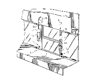
Figure 1 is a perspective view of a window assembly
according to a preferred embodiment of the present
invention;
Figure 2 is a rear view of the assembly of Figure 1
with the sash in its fully lowered position;

2158772
SJ-92a5-CA - 3 -
Figure 3 is a view similar to Figure 2 with the
sash in its most raised position;
Figure 4 is an enlarged perspective view of one
side of the window assembly in the Figure 3 position;
Figure 5 is an enlarged rear view of one side of
the assembly of Figure 3 with the weight connecting cable
intact;
Figure 6 is a view similar to Figure 5 but with a
broken cable;
Figure 7 shows the arrangement of Figure 6 with the
window blocked from falling to its most lowered position;
Figure 8 is an enlarged perspective view of the
window assembly with the sash in the Figure 7 position.
DF.TAILED DESCRIPTION ACCORDING TO TH~ PRFFERRFn
EMBODIMENTS OF THE PRESENT INVF.NTION
Figure 1 shows a window assembly generally
indicated at 1 which is well suited for use in a fast food
outlet or other similar locations. This assembly comprises
a manually operated window sash 3 which slides vertically
within its surrounding frame 5. The sash is counter-
balanced by a pair of weights 7, one to either side of the
sash. These weights are connected back to the sash by
means of cables 9 wrapping around pulleys 11. The weights
slide through vertical guides 13. A safety catch generally
indicated at 17 is provided directly below each of the
guides 13.
The weights 7 and the friction of the cables 9
around the pulleys 11 provide just the right amount of
counter-balancing to hold the sash or window in a set
position. The sash can be moved either up or down from its
set position with only a very slight manual assistance from
the window operator.

21~772
SJ-9225-CA - 4 -
Figure 2 of the drawings shows the window in its
lowermost position while Figure 3 shows the window in its
uppermost position. Here it should be noted that even when
the window is in its uppermost position, the weights 7,
when in their normal lowermost position, are located spaced
above each of the catches 17. Therefore, the weights when
connected to the sash through the cables do not interfere
with the catches in any position of their normal travel.
The purpose of the catches 17 is to ensure that if
either of the weights 7 releases from the sash because of
cable breakage, the sash without proper counter-balancing
will not fall to its lowermost position of Figure 2. As
will be seen in Figures 7 and 8 of the drawings when the
catch is activated it holds the sash such that there is a
gap G beneath the sash so that an operator does not get his
or her hands hurt by the falling sash. The details of the
window catch are seen having reference to Figure 4 of the
drawings. The catch comprises a bracket 19 secured to the
frame 5 and offset from the path of movement of weight 7.
A pin 21 projects through the bracket 19 and that pin
includes first and second legs 23 and 25. Pin 21 is
secured to the frame 5 by means of a spring 27.
Leg 23 of pin 21 normally sits on a keeper or arm
20 of the bracket 19 which holds the pin against the
pressure of spring 27 in the Figures 4 and 5 position where
the leg 25 of the pin is retracted within the frame 5
relative to the sash 3. In this position, the arm 23 of
the pin sits directly below weight 7.
In the event that the cable 9 snaps and releases
the weight 7 as shown in Figure 6 of the drawing, the
weight falls down striking the leg 23 on pin 21 causing the
pin to rotate in the bracket 19 and pushing the leg 23 off
of the keeper 20 of the bracket. Once the leg 23 of the
pin has released from the keeper, spring 27 pulls the pin

~lS~377~
SJ-9225-CA - 5 -
to the Figure 6 position where the leg 25 of the pin
projects through frame 5 into the path of the falling sash
3. Here it should be noted that the weight 7 always hangs
down farther than the sash and therefore will fall to the
Figure 6 position before the sash has a chance to reach the
same position. Accordingly, the pin end 25 is in its sash
blocking position before the sash can pass by the pin.
Figures 7 and 8 as earlier described show the pin
in its sash blocking position with the sash falling as far
as allowed by the pin and above the lowermost position that
that the sash is normally allowed to move to when the
cables holding the weights on either side of the sash
remain intact.
Although various preferred embodiments of the
present invention have been described herein in detail, it
will be appreciated by those skilled in the art, that
variations may be made thereto without departing from the
spirit of the invention or the scope of the appended
claims.

Representative Drawing
A single figure which represents the drawing illustrating the invention.
Administrative Status

2024-08-01:As part of the Next Generation Patents (NGP) transition, the Canadian Patents Database (CPD) now contains a more detailed Event History, which replicates the Event Log of our new back-office solution.

Please note that "Inactive:" events refers to events no longer in use in our new back-office solution.

For a clearer understanding of the status of the application/patent presented on this page, the site Disclaimer , as well as the definitions for Patent , Event History , Maintenance Fee  and Payment History  should be consulted.

Event History

Description Date
Inactive: IPC from MCD 2006-03-11
Time Limit for Reversal Expired 2002-09-23
Letter Sent 2001-09-21
Grant by Issuance 1999-01-12
Inactive: Final fee received 1998-09-21
Pre-grant 1998-09-21
Notice of Allowance is Issued 1998-07-13
Letter Sent 1998-07-13
Inactive: Status info is complete as of Log entry date 1998-07-06
Inactive: Application prosecuted on TS as of Log entry date 1998-07-06
Inactive: Approved for allowance (AFA) 1998-05-25
Application Published (Open to Public Inspection) 1997-03-22
All Requirements for Examination Determined Compliant 1996-09-18
Request for Examination Requirements Determined Compliant 1996-09-18

Abandonment History

There is no abandonment history.

Maintenance Fee

The last payment was received on 1998-09-09

Note : If the full payment has not been received on or before the date indicated, a further fee may be required which may be one of the following

  • the reinstatement fee;
  • the late payment fee; or
  • additional fee to reverse deemed expiry.

Patent fees are adjusted on the 1st of January every year. The amounts above are the current amounts if received by December 31 of the current year.
Please refer to the CIPO Patent Fees web page to see all current fee amounts.

Fee History

Fee Type Anniversary Year Due Date Paid Date
MF (application, 2nd anniv.) - standard 02 1997-09-22 1997-07-30
MF (application, 3rd anniv.) - standard 03 1998-09-21 1998-09-09
Final fee - standard 1998-09-21
MF (patent, 4th anniv.) - standard 1999-09-21 1999-08-04
MF (patent, 5th anniv.) - standard 2000-09-21 2000-09-15
Owners on Record

Note: Records showing the ownership history in alphabetical order.

Current Owners on Record
ALUMICOR LIMITED
Past Owners on Record
DON THOMPSON
MIRKO KOVAC
TERRY TAM
Past Owners that do not appear in the "Owners on Record" listing will appear in other documentation within the application.
Documents

To view selected files, please enter reCAPTCHA code :


To view images, click a link in the Document Description column (Temporarily unavailable). To download the documents, select one or more checkboxes in the first column and then click the "Download Selected in PDF format (Zip Archive)" or the "Download Selected as Single PDF" button.

List of published and non-published patent-specific documents on the CPD .

If you have any difficulty accessing content, you can call the Client Service Centre at 1-866-997-1936 or send them an e-mail at CIPO Client Service Centre.

({010=All Documents, 020=As Filed, 030=As Open to Public Inspection, 040=At Issuance, 050=Examination, 060=Incoming Correspondence, 070=Miscellaneous, 080=Outgoing Correspondence, 090=Payment})


Document
Description 
Date
(yyyy-mm-dd) 
Number of pages   Size of Image (KB) 
Representative drawing 1998-12-30 1 14
Description 1996-10-24 5 199
Abstract 1996-10-24 1 19
Drawings 1996-10-24 3 132
Claims 1996-10-24 2 55
Representative drawing 1997-10-20 1 32
Commissioner's Notice - Application Found Allowable 1998-07-12 1 166
Maintenance Fee Notice 2001-10-21 1 178
Correspondence 1998-09-20 1 36
Correspondence 1995-11-02 1 20
Correspondence 1997-04-07 1 28
Correspondence 1996-10-15 1 56
Correspondence 1997-09-08 1 36