Note: Descriptions are shown in the official language in which they were submitted.
r 1 r~ 11 uaY;~lu~-
- 215~851
F~R08~ED CARD PACRA&~ PROD~CTION &Y~ WIT~ NODULAR
IN~K~K8 FOR MULTIPLE FO~NR AND CARD VERIFICATION APPARATU8
CRO~Q-REFERENCE8 TO P~T-~TED APPLICATION
This application is a continuation-in-part of U.S. Paten.
Application Serial No. 08/019,865 entitled "Automatic Fmhossea
Card Package Production Apparatus and Methods" of Hill et al.
filed ~ebruary 19, 1993.
BACRGRO~ND OF T~ l~V~'~ lON
Field of the Invention
This invention generally relates to embossed card package
production systems which produce card packages including
embossed cards or the like mounted to pair card carrying
matching forms, or carriers and, more particularly, to card
inserters.
DescriPtion of the related art includinq information disclosea
under 37 CFR 1.97-1.99
Embossed card production systems such as shown in U.S.
patent No. 4,384,196 issued May 17, 1983 to McCumber et al.
entitled "Apparatus and System for Preparing Data Cards and
Mailer Forms and for Attaching Data Cards to Respectively
Associated Mailer Forms" and U.S. patent No. B1 4,034,210
reexamination certificate issued February 7, 1984 to Hill et
al. entitled "Credit Card Carriers and Methods of Manufacture"
are known which automatically mount one or more embossed
cards, such as plastic credit cards or the like, to
corresponding card carrying mailing forms, or carriers, which,
in turn, are "stuffed" into window mailing envelopes through
which the name and address of the account holder printed on
the carrier are viewable for mailing to the holder of the
account associated with the cards enclosed in the carrier.
Each of the different types of known card package
production systems and card inserters require a different kind
of form and, thus, there are a plurality of different types of
21S8851
carrier forms produced for use with these card package
production systems. In order for card issuers to
automatically issue cards using different types of carriers,
it has bene required for the issuer to produce and operate a
different type of system for each different type of form. The
versatility and thus value of these known monoform card
package production systems has therefore disadvantageously
been severely restrained.
Another problem with known embossed card package
production systems is that the carriers which are employed all
require the folding of a section of the body of the carrier
over an edge of the card to hold the card within a slot or
corner pockets. Such wedge trapping of cards
disadvantageously require a larger carrier to form the folding
section. In addition, when the carrier is unopened, it is no
longer securely mounted to the carrier and is susceptible to
inadvertent separation from the mailing carriers. Moreover,
in known carrier forms with carrier pockets, the pockets are
formed with diagonal cuts which require nonrotary oscillating
members to open the card pockets to enable card insertion.
Another difficulty with known card production systems is
the failure to obt2in full verification of the correctness of
the card embossment, the card ma~netic stripe encoding and the
information printed on the carrier. While in the card pack
production system of Hill et al., U.S. patent No. Bl 4,034,210
cited above, infor~ation from the embossed characters is
compared with information automatically obtained from the
carrier to determine there is a match, there is no independent
verification of the correctness of the information. In the
system of McCumber et al., on the other hand, no comparison is
made between the card and carrier to determine if there is a
match. Encoding on a magnetic stripe is compared against
stored data for the card and an echo check determines whether
an embossment has been made, there is no verification of
whether the embossment is the correct ~hossment or whether it
matches the encoding on the card; there is no verification of
whether the inform2tion printed on the carrier is correct or
3 2I 5 8851
whether it matches either the ~hossed or encoded information
on the card. Instead, correctness of embossed and printed
information is assumed correct and a correct match is assumed
by maintaining strict synchronization between production of
cards and corresponding characters.
Another serious problem with the card package production
system of McCumber et al. is that because of the
synchronization require to hopefully obtain a match, it is
necessary to insert incorrectly prepared cards, known to be
incorrect bec2use of incorrect magnetic stripe encoded
information, into corresponding carriers. Although this
incorrect card package is supposed to be automatically mounted
to a reject s_ation away from the correctly prepared package,
if they are not separated, an incorrect package is easily
combined with the correctly prepared packages.
Also, the versatility of the known card package
production systems is severely limited due to the fact that it
is usable with only a single type of inserter section which
can process only single type of carrier.
8~MXARY OF T~E lNV~ .lON
It is therefore the principal object of the present
invention to provide a card package production system with
full verification which overcomes the disadvantages of known
system by providing interchangeable inserter sections for
mounting different cards to different types of forms and by
providing means for mounting cards to carriers by means which
does not rely upon wedge trapping by means of folded carrier
sections or with pockets which cannot be releasably opened by
means of rollers.
This object is achieved by provision of a card production
system having an insertion station, means for delivering cards
to the insertion station for insertion into carrier forms
delivered to the insertion station and means for delivering
the forms in a preselected orientation to a loaded carrier
outlet with an interchangeable card insertion system,
4 2l5885l
comprising a first type o~ insertion apparatus to insert cards
into a first type of carrier form, means for releasably
mounting the first t~ype of insertion apparatus at the
insertion station to mount cards to the first type of carrier
form, a second type of insertion apparatus for mounting cards
to a second type of carrier form and means for releasably
inserting the second the type of insertion apparatus at the
insertion station in lieu of the first type of insertion
apparatus for inserting the cards into a second type of
carrier form.
Also, the object of the invention is partly obtained by
providing an embossed card package production system for
mechAnically mounting rectangular cards with four edges to
carrier forms with an inserter for mounting cards to the
carrier forms, comprising means for opening a pair of corner
pockets in the carrier for receipt of a pair of corners of the
card at opposite ends of one of the edges, means for inserting
the pair of corners of the card into the corner pockets and
means for moving a flap of the carrier over another one of the
edges of the card opposite the one edge to releasably hold the
pair of corners of the card in the corner pockets of the
carrier.
Further, obtainment of the object is achieved partly by
provision of an embossed card pac~age production system for
mechanically mounting cards to carrier forms with an inserter
for mounting cards to the carrier forms, comprising means for
opening a pair of corner pockets formed in part by elongate
parallel side slots in the carrier form for receipt of
opposing side edges at a pair of opposing corners of the card
including a roller with a raised edge alïgned adjacent at
least one of the elongate parallel side slots while in contact
with the body of the carrier and means for inserting the pair
of opposing side edges at the opposing corners of the card
into the corner poc~ets of the carrier.
Moreover, the o~ject ~f .he present invention is achieved
by providing an embossed card production system having means
for accessing stored embossed card information and means for
2158851
embossing a card with the stored embossed card information
with an embossed card verification system, comprising means
for reading the embossed information on the card, means for
comparing the read embossed information on the card with the
stored embossed information for the card to determine if there
is a match and means responsive to the comparing means for
automatically identifying each card for which the information
embossed on the card does not match the stored embossed
information for the card.
The object of the invention is also achieved by provision
of a method of mounting cards to a plurality of different
mailing for~s, comprising the steps of (a) automatically
mounting cards to a first type of mailing form with an
automatic card mounting apparatus having an insertion station
at which cards are mounted to forms, a card feeder for feeding
cards to the insertion station and a forms feeder adapted to
feed different types of mailing forms to the insertion
station, (b) releasably mounting a first type of insertion
apparatus at the insertion station to insert cards into a
first type of carrier, (c) automatically mounting cards to the
first type of carrier forms with the first type of insertion
apparatus, (d) removing the first type of inserter from
insertion station and mounting in its place a second type of
insertion apparatus for inserting cards into a second type of
carrier for~ and (e) automatically mounting cards to the
second type of mailing forms by using the second type of
insertion apparatus.
Still, the object of the invention is obtained by
providing an em~ossed card package production system having
means for producing cards from stored card information and
means for inserting the cards into card carrying mailing forms
with a verification system, comprising means for determining
when a card has been incorrectly prepared and means for
preventing an incorrectly prepared card from being inserted
into a carrier.
21588~1
BRIEF DE8CRIP~ION8 OF TEE DRA~ING8
The foregoing objects and advantageo~s features of the
invention will be explained in greater detail and others will
be made apparent from the detailed description of the
preferred embodiment of the present invention which is given
with reference to the several figures of the drawing, in
which:
Fig. 1 is a front view of the preferred embodiment of the
embossed card pack production system;
Fig. 2 is an illustration of a card having a magnetic
stripe and embossed character;
Figs. 3A and 3B are front views of preferred embodiments
of different types of card carrier forms preferably used in
the preferred embodiment;
Fig. 4 is a functional block diagram of the preferred
embodiment of the embossed card pack production system
illustrating the preferred steps for producing an embossed
card pack;
Fig. 5A, B and C are flow charts showing the procedural
steps of the card manufacture and insertion process of
Fig. 1;
Fig. 6A is a schematic illustration of the operation of
the card package production system when using carriers of the
type shown in Fig. 3A;
Fig. 6B is a perspective view of the preferred embodiment
of the inserter module folder, form rotation and form
rejection units of Fig. 4 used for the car.ier of Fig. 3A and
corresponding to the embodiment illustrated in Fig. 6A;
Fig. 6C is an enlarged perspective view of the preferred
embodiment of the portion of the inserter of Fig. 6B which
bends the carrier to open the ears of the corner pockets for
receipt of a card;
Fig. 6D is a partial perspective view showing how the
flap of the carrier of Fig. 3A is bent to engage with the edge
of the card during movement of corner pockets away from the
inserter;
Fig 6E is a partial perspective view showing the card
inserted in a corner pocket;
2158851
Fig. 7A is a schematic illustration of the operation of
the card package production system when using carriers of the
type shown in Fig. 3B;
Fig. /B is a perspective view of the preferred embodiment
of ~he inse~ter module folder, form rotation and form
rejection units of Fig. ~ used for the carrier of Fig. 3B and
corresponding to the embodiment illustrated in Fig. 7A;
Fig. 7C is a perspective view of the position of the
inserter o. Fig. 7A at another stop step in the inserting
seouence in which a card is held in preparation for engagement
with a carrier form of the type shown in Fig. 3B;
Fig. 7D is a perspective view of the position of the
inserter of Fig. 7C at a later step in the inserting sequence
in ~hich the card has been placed in the position for capture
within the pockets of a carrier of the type shown in Fig. 3B;
Fig. ~E is another perspective view of the inserter of
Fig. 7D at a later step in the inserting sequence in which the
card is in position for capture by the carrier;
Fig. 7F is another perspective view like that of Fig. 7E
but wit~ the pocket being opened and about to receive the
card; and
Fig. 7G is a perspective view of the inserter shown in
Fig. 7F at a later step in the inserting sequence in which the
card has been slipped into the corner pockets of the carrier
of Fig. 3A.
DE8CRIPTION OF ~ PR~FBRRBD ENBODIXENT
Referring to Fig. 1, the preferred embodiment of the
embossed card package production system 10 functions to
produce fully verified, embossed and encoded credit cards
mounted to verifiably matched carrier forms, or carriers, with
the account owner's name and mailing address printed thereon
and inserted into window envelopes that are metered with
appropriate postage and are ready for mailing.
The system 10 preferably includes a 486 DX computer 12
and an open reel tape drive 14 for controlling the operation
....
21588~1
of the system. A keyboard 13 is used for manual input of
account data and control information into the computer 12.
Information inserted into the computer 12 memory is shown at a
display screen 16 of the syste~ 10. An embosser section 20
embosses various alphanumeric characters 32 on the face of the
card 30, generally the account number and name of the account
owner associated with the card, and magnetically encodes like
information on a magnetic stripe 35 on the back of the card
30. The embossed and encoded cards 30, Fig. 2, are carried
from the embosser section 20 to a card inserter section 24.
The inserter section 24 inserts correctly embossed and encoded
cards 30 into verifiably matched and correctly printed carrier
forms 26. The carrier forms 26 hold one or more embossed
cards 30, Fig. 2, which are folded and stuffed into suitable
window envelopes (not shown) at an envelope stuffer 34. The
stuffed envelopes containing the carrier forms 26 with
matching cards 30 are transported to a postage metering
machine 18, Fig. 4 (not shown in Fig. l), to print t~e
appropriate mailing postage on the stuffed envelopes. The
materials from which these embossed card packages are produced
include blank carrier forms, or carriers, 26 and blank credit
cards or like, such as shown in the U.S. patents notod above.
The carrier forms 26 are preferably one of those shown in
Figs. 3A and 3B and a plurality of these interconnec-~ed
carrier forms 26 are fanfolded like those shown in ~.S. patent
4,034,210 issued July 5, 1977 to Hill et al., and as shown in
Fig. 1, but are without marginal pin holes for pin d~ive feed
mechanisms which are not employed in the ECPAP syste~ lO. The
printer 48 prints on both types of carrier forms the name and
address 35 and bar code 27. The cards 30 with activation
labels are mounted to the carrier by means of pocket cut into
the plane paper holes 93. For further detailed information
about the carrier of Figs. 3A and 3B, reference should be made
to U.S. Patent Application Serial No. 08/036,436 of Hill et al.
entitled "Card Carrier Forms For Automated Embossed Card
Package Production System" filed March 24, 1993,
contemporaneously herewith. After having carrier in~ormation
21588~1
g
printed on the end one of a plurality of interconnected, fan
folded carriers 26, a burster separates the end one from the
others before cards 30 are inserted.
Referring to Fig. 2, the cards 30 have a field for
receipt of ecbossed characters 32 and a magnetic stripe 35 for
receipt of magnetically encoded magnetic stripe data relating
to the account associated with the card. Common window
envelopes which have transparent sections to enable viewing of
the name and mailing address printed on the contents of the
carrier mailing form are, of course, also provided as well as
a full charge, or load, to the postage metering machine.
The system 10 housing contains a slide out drawer for
holding the tape driver 14. The blank cards 30 are stacked in
a hopper, or chute, 15 and are transported to the card
embosser encoder section 20. The cards 30 are embossed with
the stored c2rd account information such as the account
owner's name, address, card number and expiration date as seen
in Fig. 2. The embosser section 20, Fig. 1, also magnetically
encodes each card with information identifying the embossed
card 30 on the magnetic stripe 35, Fig. 2, of the card. The
embossed and encoded cards 30 which are correctly prepared are
transported _o a card labeler 60, Fig. 4, for automatic
placement of removable stick-on activation labels 21 on the
card 30. The adhered activation labels preferably are
preprinted with a telephone number of the card issuer which
the card owner calls upon receipt of the card pack through the
mail to request activation of the card for use. The correctly ! -
prepared embossed cards 30 with the affixed activation labels
are then passed to the card inserter 24 for placement in
printed card carrier forms 26. In keeping with one aspect of
the inventior., labels are only applied to cards determined to
be correctly prepared to avoid confusion between correctly and
incorrectly prepared cards.
A fan folded stack of blank carrier forms 26 are carried
through a fo~ms printer 48 by a forms feeder in the card
insertion m~dule 24. The printer 48 prints account
information such as the card account owner's name, number and
i o - 8 8 5 1
address at a name and address field 35 on the blank carrier
forms 26A and 26B. Additionally, one of a plurality of
different bar codes 27, such as interleaved two of five code,
interleaved three of nine code, Codabar ~PC-A&E code, E~N--8
code and EAN-13 code are used to encode the card account
information printed on the form 26 such as the account number
and name.
The plurality of fan folded carrier forms 26, once
printed, are sent to a form burster 36. As noted, the form
burster 36 separates the end printed car~ier forms 26 from the
fan folded plurality of carrier forms 26 to produce individual
carrier forms. In addition, in the preferred embodiment, the
form burster 36 carries a sensor for reading the code 27 from
each carrier form 26 as it is separated ~rom the fan carrier
forms 26. For further information relating to the burster,
reference should be made to U.S. Patent Application Serial No.
08/036,1590f Hill et al. entitled "Card Package Production
System With Burster and Carrier ~lerification Apparatus" filed
March 24, 1993, contemporaneously herewith. The separated
carrier forms 26 are transported to the card inserter section
24 for receipt of the embossed cards 30. As many as four
embossed cards are insertable into a single carrier form 26.
If the information embossed or encoded on the embossed
card 30 is not correctly prepared or does not match the
associated carrier form 26, the card 30 is sent to one of two
reject locations 69 and 81, Fig. 4, without being mounted to a
carrier 26 to avoid confusion. Likewise, carrier forms 26
which are not correctly prepared or do not match are rejected
and sent to a rejected form location 90, Fig. 4, without
having cards mounted to them to avoid confusion. Only
correctly prepared carrier forms 26 containing correctly
prepared and matching embossed cards 30 are folded and
transported to the envelope stuffer 34. Only the envelopes
with fully verified carriers are stuffea with the filled card
carriers 26 and are transferred to 2 postage metering machine
18, Fig. 4, to place the appropriate postage on the envelope.
Referring now particularly to Fig. 4, card account data
11 21S8851
information is stored in a card account data memory 40,
preferably a 330 Mbyte, 33 Mhz memory type for the 486 DX
computer 12 made by Everex. The card account data for as many
as ~OG,OOO accounts are stored in the memory 40 with 870 bytes
per account.
The account information preferably includes the name of
the account, or owner of the account, the account number, the
date of issuance, the date of expiration, the number of cards
per account, the credit limit as well as other account
information. The ca.d account information stored in the card
data memory 40 and the carrier form data stored in the form
data memory 44 are selectively obtainable insertable from a
number of different data input sources. A modem 22 inputs
form and card data information over a telephone line from a
remote computer (not shown) to the form data memory 44 and
card data memory ~0. Alternatively, a hardwire network 21 is
used to transfer information from a plurality of computers for
receipt at the system 10. Alternatively, a tape reel 14 or
the like is employed for inputting card and carrier form data
at the hard drive of the ECPAP system 10. This account
information is organized in blocks relating to embossments,
magnetic stripe encoding and carrier printing. At least some
of the information of each block, such as the account number,
must correspond or match some of the information of the other
blocks.
Based on this account data and control information from
manual inputs on the keyboard 13, Fig. 1, the system 10
produces the fully verified embossed card package comprising
verified correct credit cards attached to verified correct
carrier forms verified to match the attached cards within
envelopes bearing postage and ready for mailing to the account
owner at the name and address printed on the carrier. As
noted, the verification is of the utmost importance to insure
that only correctly embossed and correctly encoded cards are
attached to matching carrier forms which bear the correct name
and address of the account owner of the attached cards.
Accordingly, one separate data verification is performed on
12 - 21 5 8851
the forms 26 while three sepa~ate data verifications are
performed on the cards in addition to matching verification
between the carriers and matc~ing cards.
Referring still to Fig. , the operation of the 10 is
under control of a microprocessor based computer 12 which
communicates with the various other functional blocks as
indicated by broken line connections therebetween. Card flow
between the functional blocks is indicated with solid line
connection while carrier flow is indicated by solid bold line
connections. The microprocessor 12 is preferably a model
A80486DX-3301 or equivalent mucroprocessor made by Intel
Corporation operating at thir~y-three MHz, while the program
memory 42 and thus data memorv is contained in a single or
multiple sectored hard drive kaving a storage capacity of 330
MBytes and preferably comprises a model LXT340A made by Maxtor
Corp. An algorithm of the prcgram stored in the program
memory 42 pursuant to which t'e microprocessor 12 operates to
control the remaining electro~echanical elements of the system
10 is illustrated in Figs. 5A, SB, 5C, 6 and 7 and by the
listing of the preferred program for implementing the
algorithm of Fig. 5A, SB and rc, attached hereto as Exhibit A.
Beginning with the flow c-^ carriers 26, under control of
the microprocessor 12, blank c~rrier forms 26 from a supply of
fan folded forms 26 are then ~assed one at a time through a
forms printer 48. A carrier ~rm data memory 44 associated
with the microprocessor 12 stcres information for printing on
the blank carrier forms 26. ihe forms printer 48 then prints
on each form stored carrier fcrm information taken from the
form carrier data memory 44. ~his information is selected by
the microprocessor 12 from the form carrier data memory 44 and
relates to an associated account from the card data memory 40
including the name and mailins address of the account holder
and also including other info~ation such as the number of
cards to be attached to the carrier form, the dates of
issuance and expiration and the credit limit. In addition to
the carrier data, the forms p_inter 48 under control of the
microprocessor 12 also prints .he bar code 27 and preselected
2ls8~5l
13
graphics in c~lor, if desired, and other written information,
such as the terms of the agreement, which have been
preselected for 211 or 2 batch of carriers storPd in carrier
graphics and car-ier printing sections of the carrier form
data memory ~. Alternatively, preprinted carrier forms 27
with the preprinted carrier account data on the forms are send
directly to the form bar code reader 38 and are used for
receipt of e~Dossed cards 30 in the system 10.
The carrier account information which is unique to each
carrier 26 is also preferably printed in a machine readable
format such as a standard bar code 27. In keeping with one of
the aspects of the invention, multiple types of bar codes are
decodable ~y bar code reader 38 for enhanced versatility.
After the inaicated carrier account data has been printed on a
carrier 26, such as shown in Figs. 3A and 3B, the printed
carrier is passed via a path 50, to a form bar code reader 38
which photoelectronically senses the bar code associated with
the printed account carrier information from each carrier 26.
Obt~; n; ng one aspect of the carrier form bar code reader 38
preferably decodes the following bar codes: interleaved two of
five code, interleaved three of nine code, Codabar UPC-A&E
code, EAN-8 code and EAN-13 code. The preferred apparatus for
sensing and decoding is shown and described in the
aforementioned U.S. Patent Application Serial No.08/036,1_90f
Hill et al. entitled "Card Package Production System With
8urster and Carrier Verification Apparatus" filed March 24,
1993, contemporaneously herewith. The read carrier
information is passed via a suitable two way communication
path 52 to the microprocessor 12 which compares it to the
stored carrier information sent to the forms printer 48 via a
communication path 54 to determine if there is a match. If
the carrier account information read from the carrier 26 is
the same as the carrier data obtained from the form data
memory 44, then there will be a match and the correct printing
of the carrier 26 is verified. In that event, and if there is
a match with card information on a card 30 presented for
attachment to the carrier 26, the printed forms continue
~.,;
W~J Y41 1~47 n_llu~WlW~4~
4 21 S8~1
through the form burster 36, the forms feeder-card inserter
24, the form folder 86, the form rotation block 88 to a card
package outlet 55 to a form transporter 92 to move it to the
envelope stuffer 34, then to the inserter 24 where they are
mated with one or more verified and matching cards.
If, on the other hand, the carrier account information
read from a carrier 26 does not match the carrier information
stored in the carrier form data memory 44, then achieving~
another objective of the invention, the carrier advantageously
is sent to a carrier form rejection area 90 to prevent the
incorrect form from being stuffed into an envelope. The
carrier 26 passes through the form burster 24 to the forms
feeder-card inserter, or inserter, 24, while the card inserter
is inhibited from mounting a card. The mismatched or
incorrect carrier passes through the inserter 24 without
receiving a card. It then passes throush the form folder 86
and at the form reject rotation unit 88 it is pushed along
path 87 to the for~ reject location 90. While other bar code
readers could be utilized, preferably the form bar code reader
38 is preferably made by Opto Technology as part number QTR
while preferably the decoding is performed by a forty pin IC
made by Hewlett Packard under part number HBCR-1800.
Reference should be made to U.S. Patent Application Serial No.
08/036,439 of Kassabian et al. entitled "Card Package
Production System With Modular Carrier Folding Apparatus for
Multiple Forms" filed March 24, 1993, contemporaneously
herewith, for further information relating to the preferred
form of the apparatus for rejecting the incorrect carriers.
While the carrier forms 26 pass through the forms printer
48 and to the inserter 24, the cards 30 make a similar journey
from a stack of cards 30 through a blank cards feeder 58, a
card graphics module 62, a card embosser/encoder/infill unit
20, an on line jitter tester 82, an embossed card mag stripe
reader 57, an embossed card transporter, a card mag stripe
reader 64, an embossed character reader 70 and a labeler to
the card inserter 24.
The blank cards feeder 58 passes blank cards one at a
2158851
time to a card graphics module 62 which inputs graphic
lettering and designs selectively in color on the blank card -
s--f2ce. The card embosser 20 is preferably of the general
type sho~m in U. S. patent ~,969,760 issued November 13, 1990
to La~anna et al., or the like. The selected card graphics
and card printing infor~ation is stored in a card graphics and
card printing data section of the program memory 42 and
relates to information ,hat applies to all cards or a batch of
cards and is not unique to each card, as distinguished from
the card account data.
The card embosser 20 embosses the card account embossed
information into each card in accordance with continued inputs
sent via a communication path 68 which are determined by the
microprocessor 12 from ~e card account embossed data section
of the card data memory ~O. T~e embossed card 30 is then sent
to the card magnetic stripe encoder of the embosser/encoder
unit 20 which encodes the magnetic stripe 35, Fig. 2, on the
card 30 with magnetic s ~ipe card information received on the
communication path 68 from the microprocessor 12 which, in
turn, it obtains from a magnetic stripe card encoding data
section of the card data memory 40.
An embossed card magnetic stripe reader ~7 reads and
decodes information encoded on the magnetic stripe 35, Fig. 2,
of the card 30 and compares it with the card account embossed
information sent from the card data memory and read by the
embossed character reader 70, Fig. 4. In addition, the read
encoded information is compared to the encoded account
information stored in card data memory 40 used to encode the
card. If the encoded information on the magnetic stripe 35,
Fig. 3, does not match stored card account information, does
not match the ~hossed information read from the card or the
em~ossed information read from the card does not match the
stored embossed account data,then the embossed and encoded
card 30 is sent to an em~osser card reject area 69. Since the
card is incorrectly encoded, it is advantageously prevented
from being inserted into a carrier form 26 and stuffed into an
envelope to achieve one aspect of the objective of the
215~851
16
invention. If the card is correctly encoded, based on the
reading by the embosser card M/S reader, the embossed and
encoded cards 30 are then moved via the embossed/encoded card
transporter 66 to the card magnetic stripe, or ~ reader 64,
and the card embossed character reader 70 which respectively
receives what is read by each via paths 72 and 74 and makes
comparison to account data stored in the card data memory for
each and also compares what is read by each to each other.
The embossed character reader 70 is preferably of the type
shown in U.S. patent B1 4,194,685 of Hill et al. entitled
"Verifying Insertion System Apparatus and Method of Operation"
issued ~arch 25, 1980, reissue certificate issued February 19,
1985.
While other devices could be used successfully,
preferably the embossed character reader 70 is made by
Dynetics Engineering Corporation and is shown in U.S. Patent
No. 4,215,813, while the magnetic stripe reader 64 is
preferably made by Brush Industries under part number 901-529-
O.
Coupled with the 486 DX computer 12 is a manually
operated card jitter tester and analyzer 80 quality check tool
built by Q-Card Corp. of Owings Mills, Maryland. A card is
manually run through the jitter tester 80 and the computer 12
analyzes the encoding at seventy-five bits per inch of the
card for track one and two hundred ten bits per inch for
tracks two and three. The card jitter tester and analyzer 80
qraphically displays a JTlA report on the display screen 16,
Fig. 1, or on a print out indicating if the tested card has
been properly encoded. Alternatively, an on line jitter
tester 82 is placed for receipt of cards exiting the card.
embosser/encoder 20. Prior to carrying the embossed and
encoded cards 30 to the card labeler 60 by the transporter 66,
the on line card jitter tester and analyzer 82 reads the cards
to verify proper encoding. Preferably, the jitter tester and
analyzer 80 is like one made by Q-Card Company of Owing Mills,
Maryland and the on line jitter tester 82 is the same as
jitter tester 80 but with a computer interface and automatic
v ~ r~ l /ua~ l/u~
2158~51
17
card transporter provided.
The microprocessor 12 compares each reading of the
embossed information on the card 30 by the photoptical
embossed character reader 70 and the magnetic s~ripe reader 6'
to the acco~nt data information stored in the appropriate
section of the data memory 40 and to each other.
Advantageously, the information decoded from the magnetic
stripe 35, Fig. 2, of the card 30 by the magnetic stripe
reader 64 is compared with the embossed card character
informatio~ read by the embossed character reader 70 to
determine if there is a match. If there is a match of
information, the card 30 is internally verified to be correct,
and is passed to the inserter 24. If the coded information
from the magnetic stripe reader 64 does not match the embossed
character information on the card read by the embossed
character reader 70 do not match each other, then the
microprocessor 12 identifies the card as being incorrectly
ossed or encoded and the card is rejected before insertion
into a carrier.
After checking the embossed cards 30 for correctness and
automatically rejecting the identified incorrect cards, the
card transp~rter 66, under the control of the microprocessor
12, enables the card labeler 60 to label only those. The card
labeler 60 automatically applies removable informational
labels, such as stick-on card activation labels 21, Figs. 3A
and 3B, to only the correct cards 30. The computer 12 through
means of card labeler 60 or, alternatively, the card labeler
itself, accumulates information concerning the total number of
informational labels applied to the cards 30 and the total
number of correct cards. The passing of the correct cards 30
to the labeler is selectively performed either manually or
automatically in a single card production apparatus 10, while
the labeling is produced only automatically and only on
verified correc~ cards. In this way, correct cards with
labels are readily distinguished from rejected cards without
labels.
The inserter 24, under control of reports from the
f----
~ U ~ r ~ 7~ W~
215885 1
18
microprocessor 12 via a communication path 76 causes the
internally verified card 30 to be mounted to a matching
carrier 26. Advantageously, the microprocessor via
communication path 52 compares the coded carrier information
read from the form bar code reader 38 with the coded card
information read from the magnetic stripe reader 64 and the
embossed information read by the embossed character reader 70
to determine if there is a match and thereby eliminates the
need for synchronization between card and carrier production
to achieve a match without verification. Advantageously, the
card inserter 24 rejects the cards 30 ~hich do not match the
carrier information decoded from the carrier 26 before
insertion into a carrier. The nonmatching cards are sent to
an inserter card reject area 81 and the empty carrier 26 is
separately sent to a carrier form reject area 90. Cards 30
having information which does not match the carrier
information or the stored account information are prevented
from being inserted into the corresponding carrier at the card
inserter 24. The embossed cards 30 which have card
information that do match the decoded carrier information are
mounted to the matching carrier 26 at the card inserter 24.
One or more cards 30 are selectively insertable into a
single matching carrier form 26. The automatic card mounting
apparatus or card inserter 24 is located at an insertion
station at which cards 30 are mounted to carrier forms 26
including those shown in Figs. 3A and 3B. The embossed card
package production system 10 routes cards 30 to a plurality of
different carrier mailing forms 26. Referring to Figs. 3A and
3B two types of carrier forms 26A and 26B employed in the
system 10, Fig. 1, are shown holding embossed cards 30. The
first type of form 26A, Fig. 3A, is flexi~le planar body 93
having a pair of spaced parallel ear shaped slots, or corner
pockets, 28 for receipt of the sides 31 of a card 30 and one
of either the top or the bottom of the card. The form 26A has
a bottom flap, or lip, 33 for receipt of the other of the top
or bottom or the card 30. The corner pockets 28 and the lip
33 are cut from the flexible planar body 93. The card 30 is
WU Y~l'15~7 t'~ i ~U~Yl!tl.~
2158851
19
held between the pockets 28 and the lip 33 at a location
spaced from the periphery of the body 93. The corner pockets
28 hold the card 30 against movement in three of four possibie
rectilinear directions. The lip 33 engages with an edge of
.he card 30 and is intermediate to the corners of the card to
hold the card 30 against movement in the fourth possible
rectilinear direction.
A second type of carrier form 26B seen in Fig. 3B has a
flexible planar body 93 with a pair of parallel spaced side
slot sections 29 and 2 fold 89 to hold the card 30 within the
side slots. The mailing form 26B has a pair of rectilinear
slots 39 cu. in the body 93 to form a pair of opposed corner
pockets for receipt of opposed corners 41 of the card 30. The
rectilinear slots 39 have a pair of parallel spaced slot
sections 29 and a cross slot section 43 transversely extending
between the pair of parallel spaced slot sections 29. In
the form of Fig. 3A, the corner pockets open away from the
leading end section and the address and toward the bar code
field 27 while in the carrier of Fig. 3B, the address is
located on the lagging end section while the pockets face
toward the bar coding and away from the leading edge.
Reference should be made to U.S. Patent Application Serial No.
08/036,436 of Hill et al. entitled "Card Carrier Forms For
Automated Embossed Card Package Production System" filed March
24, 1993, contemporaneously herewith, for further details
about each of these different types of carriers.
In the system 10 a card feeder or transporter 66 feeds
cards 30 to the insertion station at which a card inserter 24
is located. The card inserter module 24 includes a forms
feeder adapted to feed the different types of mailing carrier
forms 26A and 26B from the fan of folded carriers to an
insertion station. A first type of card insertion apparatus
24 is releasably mounted at the insertion station to insert
cards 30 into one type of form carrier 26A. The card inserter
24 automatically mounts embossed cards 30 to the first type of
carrier for~s 26A. To insert cards 30 into a different or
second type of carrier 26B in the ECPAP system lO, the first
21 5 ~ 51
type of inserter is removed from the insertion station and
mounted in its place is a second type of card insertion
apparatus for inserting cards into the second type of carrier
form 26B. The embossed cards 30 are automatically mounted to
the second type of carrier mailing form 26B by using the
second type of insertion apparatus.
After all the cards 30 have been attached to a matching
carrier form 26, the inserter 24 passes the filled carrier
form via path 84 to a form folder 86. The form folder 8~
folds the loaded carrier 26 along two perforation lines 89,
Fig. 3, to divide the carrier into three equal areas. As with
the inserters, two different types of folders are
alternatively employed for folding different types of
carriers. The folded carrier forms 26 are rotated by an arm
at a form rotation station 88 for insertion into mailing
envelopes. Before being rotated, the form of Fig. 3A is
flipped over after folding while the form of Fig. 3B does not
and therefore different folders are used when there are
different carrier forms. Empty carrier forms 26 which do not
match with a corresponding card or are otherwise improperly
prepared are sent via a transportation path 87 to 2 form
reject area 90 to avoid place~ent into mailing envelopes. The
preferred embodiment of the form folder 86, form rotation unit
88, form reject unit 90 and form transporter to envelope
stuffer 92 are shown in U.S. Patent Application Serial No.
08/036,439 of Kassabian et al. entitled "Card Package Production
System With Modular Carrier Folding Apparatus For Multiple
Forms" filed March 24, 1993, contemporaneously herewith, and
reference should be made thereto for details of how the
different carriers of Figs. 3A and 3B are folded different to
point them both to the envelope stuffer in the correct
orientation.
Folded carriers 26 with correctly matched embossed cards
30 are carried along a form transporter 92 to the envelope
stuffer 34. The envelope stuffer 18 preferably used is a
Pitney Bowes Spectrum Model F400. The envelope stuffer 34
places the filled and folded carrier form 26 into a window
21S88~1
21
envelope from a supply of window envelopes. The stuffed
envelopes are then sealed and passed to a postage metering
machine (not sho~) whicn applies correct postage to the
envelope. The postage metering ~achine used is preferably one
made by Pi~ey Bowes such as Paragon Mail Processor Model Nos.
USS4 - USS9, Eagle Model E660 or E670, or a Model 5300 or
5636.
Also preferably performed in the embossed card package
production apparatus 10 is a method of mounting cards to a
plurality of different mailing forms, comprising the steps of
(a) automatically mounting cards to a first type of mailing
form with an automatic card mounting apparatus having an
insertion station at which cards are mounted to forms, a card
feeder for feeding cards to the insertion station and a forms
feeder adapted to feed different types of mailing forms to the
insertion station, (b) releasably mounting a first type of
insertion apparatus at the insertion station to insert cards
into a first type of carrier, (c) automatically mounting cards
to the first type of carrier forms with the first type of
insertion apparatus,
(d) removing the first type of inserter from insertion station
and mounting in its place a second type of insertion apparatus
for inserting cards into a second type of carrier form and
(e) automatically mounting cards to the second type of mailing
forms by uslng the second type of insertion apparatus. For
details of the methods of operation, reference should be made
to U.S. Patent Application Serial No.08/03~,657 of Hill et al.
entitled "Automatic Verified Embossed Card Package Production
Methods" filed March 24, 1993, contemporaneously herewith.
Also, performed in the embossed card package production
apparatus 10 is an improved verification system, comprising
means for determining when a card has been incorrectly
prepared and means for preventing an incorrectly prepared card
from being inserted into a carrier.
Referring now to Fig. SA, the computer 12 retrieves
customer account information in step 100 including the name of
the custome~, the account number, the date of issuance, the
r, ~-
. 2158851
22
date of expiration as well as other information. In step 102
the account information is transferred to the embosser while
in step 108 the form printer receives the customer mailing
information. In step 104 the blank card is embossed and the
magnetic stripe encoded with the account information while in
step 110 the form is printed with the customer mailing --
information.
In step 106 the card is read back and verified with the
computer file while in step 112 the form is separated from the
stock and read at the bursting station. In step 114 the
computer file, the embossed card information read from the
card, the encoded information read from the card, and the
printed information read from the carrier form are all
compared together to determine if there is a match. In step
116 a determination is made as to whether all the information
is correct.
Referring now also to Fig. 5B, if all the information is
not correct, the error is processed in step 118. In step 120
the counter verifies if the embossing and encoding are
correct. If an e-ror is detected, in step 122 the counter
will cause rejection of the card and will then in step 124
cause a new card tO be embossed and encoded. In step 126,
after the new card is prepared, the counter returns to step
114 to compare the new card to determine if the new card has
been properly prepared.
If in step 121 the card is verified to be prepared
correctly, in step 128 the form will reread and in step 130 a
comparison will be made to verify if the form and computer
file match. If the form matches the file, the form and card
are then processed in step 120 detailed in Fig. 5C.
If the form is correct, the form is ejected in step 132,
a new form is printed in step 134, and the new form is read in
step 136. In step 138 the new form is compared to the data
file. If the file matches the form, a decision is made to
process the card and form. If a discrepancy still occurs, the
microprocessor based computer will stop the operation in step
140 and operator intervention is required.
n U ~;~/Ll:~ l / r~_ 1 / ua~lu.~ ~
215885l
23
Referring now to Fig. 5C, if the embossed encoded card,
the printed carrier form and the information in the computer
file match and a de~ision has b2en made to process in step
120, in ste? 142 the computer 1~ causes the cards to be
inserted into the ca~rier form and then in step 144 fold the
carrier forms are folded closed for insertion into envelopes.
The forms are then turned ninety degrees in step 146 so that
the forms are in proper alignment for insertion into an
envelope by an envelope stuffer.
In step 148 the computer 12 checks i~ the envelope
stuffer is ready for receipt of a form. If not ready, the
computer 12 pauses in step 1~6 to allow the operator readies
the stuffer in step 1~8. After it is determined in step 148
that the envelope stuffer is ready, the stuffed carrier forms
are sent to the envelope stuffer in step 150.
The microprocessor based computer 12 selects the next
customer account record in step 152 and returns to the start
process 100, Fig. 5A, in step 154.
Referring now to Fig. 6A, a preferred embodiment of the
portion of the card package production system 10 following the
embossed/encoded card transfer 66 from the card embosser 20 is
schematically illustrated with the card inserter function 24,
as well as the form folder function 86, performed by an
inserter apparatus 2~A and a folder apparatus 86A especially
adapted to insert cards into and fold carriers of the type
shown in Fig. 3A.
The cards 30 come down a slide 160, are transported past
the mag stripe reader 64 and embossed character reader 20 to
the second of two card loading stations 162 and 164 at the
inserter 24A, if the card is to be loaded into the second of
two card mounting locations 166 and 168. If not, the card 30
is moved only to the first loading station 162 to be mounted
into card mounting location 166.
A fan folded plurality of interconnected carrier forms
26A and moved to the ~urster 36 after being printed with
carrier information by the forms printer 48. The bar code 27
printed on the carrier is read during the bursting operation.
24
After the cards 30 are veirified and the carrier 26A has been
verified, the end carrie~ form 26A is forced to conform to the
cylindrical surface of a roller 170 which causes the ears of
corner pocket:s 31 to open and pusher members 172 and 174 to
push the cards into the corner pockets. The carrier form
continues to roll away from the inserter with the cards in the
pockets and the lip 33 on the card then prints up and over the
edge of the card 30 to hold it within the pockets 31, as best
seen in Fig. 6E. The form is then pushed against a pivotally
mounted stop member 176 until the leading end section 178 and
middle card carrying section 180 buc3cle along fold line 89
away from the folding path 182. A pusher arm 184 then pushes
against the middle section 180 adjacent the lagging fold line
89 until the carrier 30 is completely folded as shown. A
pushing member 186 then pushes the folded carrier against a
pivot pin 188 to rotate the folder form at the for3l rotation
station 88. The folded form is then moved along a path 190 by
pusher 191 toward an envelope stuffer 34 (rotation) or to an
output stack of loaded carriers 26A' to the front reject
location 90 (not shown).
Still referring to Fig. 6A, if the card 30 is not
prepared correctly or does not match the carrier, then the
rejected cards 301 are moved past the insertion stations 162
and 164 and down a chute 192 to prevent if from being loaded
into a carrier 26A.
Referring to Fig. 6B, similar action is taken with a
carrier which is incorrectly prepared or does not match a
card. In that event, no card 30 is loaded prior to passing
the carrier 26A through the folder 86A and to the form
rotation module 88. However, instead of the pushers 191
pushing the empty carrier along path 190 as shown in Fig. 6A,
the pusher 191 only pushes the empty carrier 26A into the path
194 of the pusher 186 which then pushes it away from the path
190 to the form reject location 90 (not shown) in the
direction of arrow 193.
Referring now to Figs. 6C, D and E, the preferred
embodiment of the inserter 26A module and folder 86A module is
21588~1
shown in which a pushing apparatus 202 for pushing the folded
carrier is to a load position. The card 30 is moved by a
conveyor belt of the card transporter 66 to the carrier
loading positions when they are pushed into the pockets of the
carriers 26A held below a roller 198 and a roller 200.
Referring to Figs. 6D and E, it is seen how the ears 210
of the pockets 28 open to receive the card 30 as the carrier
is turned b~low rollers 198 and 200, Figs. 6B and 6C. In Fig.
6E, the fla~ 33 is shown resiliently flowing up and over the
edge of the card 30 as the adjacent portion of the carrier 26A
is bent passing the roller 198. The roller 200 is driven by a
motor 214 controlled by the computer 12.
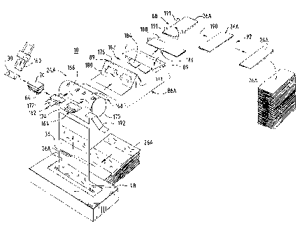
Referring now to Fig. 7A, a preferred embodiment of the
portion of the card package production system 10 following the
embossed/encoded card transfer 66 from the card embosser 20 in
which the card inserter function 24 as well as the form folder
function 86 are performed by an inserter apparatus 24B and a
folder apparatus 86B which are especially adapted to insert
cards into he carrier of the type shown in Fig. 3B. As seen
from a comparison of Figs. 6A and 7A, the remainder of the
system 10 remains the same and the inserter 24A and folder 86B
are directl~ substitutable for the member 26A and folder 86A
since they both receive cards and carriers in the same way and
in the same location and output loaded carriers to an envelope
stuffer in the same orientation, direction and location. The
modules cont~ining different inserters and folders are of the
same size and adapted to releasably fit with the other
elements of the system to ena~le them to be interchanged so
that the multiple forms of different types can be processed in
the one sys.em.
Because the carrier form 26A operates differently and
because the address 35 is located on the end panel separate
the one on ~hich the address is located on the sarrier form
26A, the ca-rier form 26B is folded differently and is flipped
over on its side before being passed to the form rotation
module and the envelope stuffer 34.
The feeding of the card 30 and the carrier 26B to the
2ls88sl
26
inserter 24B and the reject of incorrect cards 30 and
incorrect carriers 26B is performed the same way as with the
inserter 24A and fold 86A as shown in Figs. 6A, 6B and 6C.
Presuming that neither the card nor the carrier are
rejected, the cards 30 are held by a card holding mechanism
196 where they are held until the carrier 26B moves by in the
direction of arrow 308. The pockets are opened by rollers 300
and 310. The loaded carrier are then pushed up a guide wall
312 to a stop member at the top of the guide wall. In this
position, the leading fold line is aligned with a folding gap
at the base of the wall 312 and continued pl)ch;ng causes it to
buckle at the leading fold line and pass through the gap fold
line first.
The folded edge of the carrier 26B is then engaged by a
stop member 314. Another pushing member (not shown) then
pushes the lagging edge of the carrier form along the folding
path 182 until it tips over the stop member 314 as shown by
arrow 316. The address in the lagging panel now faces upward,
and the carrier 26B is turned and moved to the envelope
stuffer as previously described with reference to Fig. 7A,
etc.
Referring now to Fig. 7B, the cards 30 are moved into
engagement with a card holding assembly 206 after they are
moved there by a card conveyor 202 which drive the cards
toward the card holding assembly 206 by means of a pulley 20i
powered by a motor 204 under control of the computer 12. The
card holding apparatus 196 has a hinge plate 206 with a pair
of legs 208 upon which the cards are supported as best seen in
Fig. 7E. As seen in Figs. 7G and 7~, the carrier travels
adjacent a roller 320 which opens the pocket of the carrier
26B. The card is first moved to the position shown in Fig.
7C. Once moved past the legs 208, the plate 206 pivots to
drop the card 30 into the carrier as shown in Figs. 7E and 7G.
In Fig. 7C the cards are moved into loading position adjacent
the card holding apparatus 194 by the pushing member,
associated with the conveyor belt 322, Fig. 7C.
While a detailed description of the preferred embodiment
~Y~/21~7 PCT~S9~/03~2
27 21 5 88 51
of the invention has been given, it should be appreciated that
many variations can be made thereto without departing form the
scope of the invention as set forth in the appended claims.