Note: Descriptions are shown in the official language in which they were submitted.
DUCTED FAN MOWER DECK 21 5 8 8 8 ~
FIELD OF INVENTION
This invention relates to an improved mower deck.
BACE~GROUND OF THE INVENTION.
Rotary mower decks typically ~lave a single or
multiple blade which cuts vegetation by the rotation of such
blades in a controlled area such as under~eath a mower deck.
Typically, this mower dec}c includes a single discharge chute
which faces either to the side or, occasionally, to the rear of
the associated frame which supports same for travel over the
ground. These mower declcs need a large volume of air in order
to provide f or the movement of grass clippings underneath the
deck and through the discharge chute. Typically, this volume
of air is provided by having the lower lip of the lower deck
spaced from the ground such that the needed air can travel
between the mower deck and the ground before being passed
through the discharge chute. ~owever, this distance provides
for a space wherein the noise of the blades can pass to the
outside world and, in addition, limits tl~e shortest length of
cut for the blades.
04-7462 Page 1 04/ ~ /95
~ !' 21~888~
OBJEcTs OF Sm~MARy OF ~ NVENTIoN
It is an object of this present invention to increase
the efficiency of mower decks.
It is another obj ect of the present invention to
allow for increased depth of the sidewall of a mower deck.
It is yet another object to the present invention to
increase the effic:iency of the dispersal of grass clippings in
a mower deck.
It is still another object of present invention to
reduce the plugging and/or to grass build-up within the
confines of the mower deck.
It is a further object of the present invention to
increase the bagging efficiency of mower decks.
Other objects and more complete understanding of the
invention may be had by referring to the drawings in which:
BRIEF ~E~RIP~ION QF T~E 12RAWINGS
Structure, operation, and advantages are presently
disclosed preferred embodim~nt of the invention will become
apparent when consideration of th~ following description taken
in conjunction with the accompanying drawings wllerein;
Figure l is a diac~ram of the airflow created by the
invention in a mower deck.
04-7462 - Page 2 04/13/95
21~889
Pigure 2 is an enlarged drawing of the area of the
trailing edge of tlle mower deck diagram of Figure l.
Figure 3 is a downward-looking view of a mower deck
incorporating the inventioil of the application,
Figure 4 is a pe~^spective view of the mower deck of
Figure 3, and
Figure 5 is an enlargement of the area :,u--~ul~ding
the spindle of the mower deck of Figure 3.
DETAILED DESCF~IPTION OF THE INVENTION
The invention of this application is directed to the
use of high-pressure air in order to improve the cutting
efficiency of rotary lawn mowers. The invention has particular
application to lawn mowers having cutting aecks extremely close
to the ground andlor decks otherwise having a reduced volume of
air passing through the deck and/or out the discharge chute.
The invention will be described in an embodiment incorporating
a single 30 inch blade in a rear discharge type riding lawn
mower .
The invention of this application relates to
incorporation of a pressure differential creating device to be
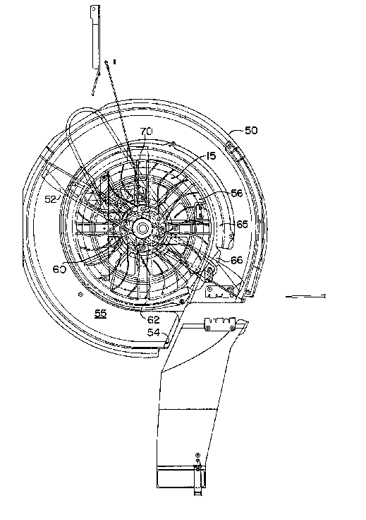
associated wit}l a niower dcck 50 having a discharge chut~ 51 and
a rotary blade 52_
In the typical mower deck, when the blade is rotated
at slow speeds, operated l~nder heavy loading conditions andlor
the deck is deprived of a rapid-flow of replacement air, there
is a tendency to clog or ~uild up grass clumps throug}lout the
confines of the mo~er dec]c; most particularly at the trailing
edge 54 of t}le discharge chute. It is at this location that
04-746Z Page 3 04113195
21~8889
any build up is particularly troublesome because, as grass
clippings build up at this location, they al50 reduce the
cross-sectional area of the discharge chute and disrupt the
laminar flow of the circulating air around the conflnes of the
mower deck.
The present invention eliviates this problem by
incorporating an additional pressure differential creating
device with the mower deck, such pressure differential device
increasing the pressure and velocity of air unaerneath the
mower deck, most particularly at the trailing edge 54 of the
discharge chute. This pressure differential device acts to
increase the velocity of air underneath the mower deck as well
as encouraging the vegetation residue to travel through the
discharge chute 51 and not build up at the trailing edge 54 or
elsewhere .
In the preferrcd embodiment, the mower deck 50 is a
30 inch singe-bladed rear discharge mower deck for use with a
riding lawn mower. l'.lthough this particular deck is a
single-bladed rear discharge design, it could be understood
that the invention could be utilized with side-to-s;de multiple
spindle mower decks as well as other rotary mower devices that
could utilize an increase in pressure differential, most
particularly at the trailing edge of a discharge chute. These
mower decks may be suspencled from the underneath of a riding
mower, may be interconnected to the ront, or may be
interconnected to the bac}. of the associated power vehicle as
known in the a~t.
The particular mower deck 50 disclosed also includes
sidewalls 53 which extend downward into the vegetation further
04-7462 Page 4 04/13~95
2 1 ~88~
. ~ ,
tllan in ordinary mower decks. The purpose for this particular
adaitional extension is to reduce the blade noise which escapes
from underneath the mower deck 50 While advantageous, this
e~tension of the sidewall 53 downward also has the effect of
further reducing the amount of air which can be utilized by the
blade otherwise used to create a high enough velocity air-flow
to provide for satisfactory mowing under all conditions.
Particularly troublesome are wet lawns having a high blue grass
or other high density concentration of grass blades.
In even a conventional deck, under these
circumstances, the air flow caused by the rotary blade 52
underneath the mower deck would be disrupted, causing
vegetation build-up on the trailing edge 54 of the discharge
chute 51 and otherwise clogging up the laminar air flow which
would preferably be present for smooth discharge. With the
increased sidewalls of the present preferred embodiment the
problem would otherwise be exacerbated.
The precent differential pressure device remedies
these problems by providing an extra source of high velocity
air underneath the discharge chute and, most particularly, at
the trailing edge 54 of th~ discharge chut~ 51. This pressure
dif ferential device increases the apparent velocity of air at
the discharge chute, thus to incr~ase the discharge efficiency
at this critical point wh ile also protecting the trailing edge
52 of the discharge chute against undesired residue buildup.
As shown in Figure 2 tlle direction and location of
the pressurized air in respect to the trailing edge of the
discharge chute can vary. The most efficient location is
tangential 56 to the path of the mower blade directed straight
04-~4~;2 Page 5 04/13/95
... . . .. , .. , _ _ _ _ _ .. , ~ . . .
21~888~
at the trailing edge or slightly upstream thereof. This
crcates a relatively hig~l E~ressure air stream at this location,
tllus encouraging tl~e grass clippings to pass out of the
discharge chute. As represented in Figure 2, the actual
location and direction of l~he air stream may vary. Keeping the
air stream direction the same, movement radially of the center
of the mower deck has a minimal additional effect on the air
flow. Elowever, angling the air flow at an angle greater than
tangential (i.e. over 90 deg. in respect to a radial line to
the point of departure) causes a certain amount of parasitical
power loss via conflicting air streams (and thus is not
preferred). An angle of Elus or minus 20~; is disclosed, as is
a radial displacement 57 of plus 3 minus 1.5 inches (in a 30"
deck). In general the greater the radial displacement, the
lesser the angle should be and the hig~-~r the auxiliary air
pressure must be (and vice-versa).
The pressurized air can be provided by any motor
driven fan, either integral with the mower deck or separate
therefrom. For example, (l small separate blower mounted above
the mower deck and driven by a belt would be appropriate in
units wllere the size and ~complexity of an integral fan causes
design compromises such as multi-spindle side by side mower
decks .
The particular p~essure differential device disclosed
is a radial fan 15 formed integr~lly wit~l the spindle 60 of the
rotary blade 52 in a conf ined space 58 on tlle underside of tile
top 55 of the mower deck. It is preferred that tlle space 58 be
created through the addition of a suppl~mental piece 61 which
is separately bolted to the bottom of the mower deck 50 so as
04-7462 Page 6 04~13/95
.. . . . . . ..... . . . . . .. ...
~ ~ , 2l~88~
to not disturb the integrity of the top 55 of the mower deck,
most particularly at the critical location of the mountlng of
the spindle 60.
In that the particular pressure differential device
disclosed is radial fan 15, the separate piece 61 is mounted
off center in respect to the axis of rotation of the radial fan
so as to provide a increasirlg cross section generally spiraling
air passage 65 surrounding the radial fan. The smallest
cross-section 62 of this air passage 65 is located at or
sllghtly downward of the critical trailing edge 52 of the
discharge chute with the f an opening 66 ~eing located near to
t~le discharge chute directed tangentially substantially towards
or slightly upstream of the trailing edge 54 of the discharge
chute 52. In this respect it is noted that the minimum
diameter cross sectional area 62 encourages the f low of air
through the fan opening 66 3~y creating an air restriction
downstream of the fan opening. Further, the generally
spiraling air passage 65 produces a smooth laminar flow of air
out of the fan opening ~6, thus maximizing the efflciency of
the air f low at t~lis particular location.
In the particular embodiment disclosed, since the fan
is a radial fan 15, it obtains its source of air through a
series of holes 70 provided in the top 55 of the mower deck
nearest the central axis of rotation of the radial fan. These
holes 70 allow for the radial fan to pull air therefrom and
t~lencc outward, tl~us pressurizing the air in the increasing
cross section spiraling air passage 65.
The holes 70 are themselves of a unique configuration
so as to maximize deck strength w~lile reducing manufacturing
04-7462 Page 7 04~13/95
,, . 21~88~
complexity. In specific, in the normal mowing deck the spindle
is mounted in a central circular hole having an inner diameter
only slightly morc than the outer diameter of the spindle.
Note that with differing spindles the number and
shape of the cloverleaf would vary. While it is technically
possible for one to merely enlarge the central hole or add
additional surrounding holes to provide a source of air for the
fan 15, these both reduce the strength of the deck as well as,
especially for the former, increasing the size, cost and
complexity of the spindle (which now has to be self supporting
over a longer distance than otherwise). In contrast in the
present invention the hole 70 is of cloverleaf 72 shape
complementing the four support arms of the spindle 60. The
edges of the cloverleaf 72 are folded (down preferably) so as
to create reinforcing flanges - t~lUs, stiffening the deck at
this critical location ~the hole shape would vary dependent on
the spindle). This pattern allows the drive spindle 60 to
remain the same size as in a conventional deck without
compromising the strength of thc unit w~lile still providing t~le
needed air passaqe. By llaving the spindle in such a location,
t~le air passing over it also cools the critical bearings and
keeps the belt area cleaner than ot~lerwise.
Although the in~ention has becn described as
preferred embodiment in a certain degree of particularity, it
is understood that numerous changes can be made without
deviating from t~le inv~ntion as hereinafter claimed
04-7462 Page 8 04/13/95