Note: Descriptions are shown in the official language in which they were submitted.
2 1 5 8 g 9 9
!
REFRIGERATION SYSTEM WITH
PULSED EJECTOR AND VERTICAL EVAPORATOR
Cross Reference to Related Applications
This application is a continuation-in-part of co-
pending application entitled "Non-Steady-State Self-
Regulating Intermittent Flow Thermodynamic System" filed
March 25, 1993 and given Serial No. 08/036,901, the
applicant of which is one of the applicants of the present
application, and co-pending continuation-in-part
application entitled "Circulation of Oil in Refrigeration
Systems with Immiscible Refrigerant-Oil Combinations" filed
June 20, 1994-and given Serial No. 08/262,680, the
applicants of which are the same as those of the present
application.
Background of the Invention
This invention concerns an extension of the
technology described in the aforementioned related co-
pending applications, particularly with respect to
inclusion of pulsed ejectors in combination with nozzling
devices which generate high velocity bursts of
substantially unrestricted refrigerant flow throughout a
refrigeration system. United States Patent No. 5,240,384
describes a refrigeration system utilizing ejectors having
partitioned mixing tubes or diffusers to create multiple
flow passages in each of which the primary high velocity
fluid jet stream effectively pulses. However that
pulsation is an internal process within the ejector body
- ~15~99
and it does not change the conventional steady-state
continuous fluid flow throughout the system. In contrast
the concept upon which the present invention is based is
that of a substantially non-steady-state intermittent flow
throughout the entire system.
Refrigeration cycles typically include a vapor
compressor, a condenser which changes vapor to liquid as it
gives off heat, an expansion device reducing the
refrigerant pressure, and an evaporator changing liquid to
vapor as it provides cooling. Expansion devices of the
prior art are inefficient because of energy loss during the
throttling process. Also optimum ~se of evaporator surface
area is limited when conventional expansion devices are
used because of the requirement of substantial superheat of
refrigerant vapor by a portion of the evaporator. For
highest efficiency the entire surface area of an evaporator
should be fully wetted but with conventional expansion
devices full wetting of the evaporator surface is not
possible because the compressor must be protected from wet
gas or liquid.
Evaporator and condenser heat exchange tubing of
the prior art is typically of serpentine configuration with
horizontal tubing having a multiplicity of U-bends. An
appreciable pressure drop is inherent in such heat
exchanger designs in order to move oil along with the
refrigerant and achieve appropriate heat transfer rates.
High pressure drops lower overall system efficiency and
215g~'9~
increase the compressor pumping power requirements. Also,
horizontal evaporator and condenser tubing can result in
laminar non-turbulent flow with associated low heat
transfer rates. Condensed liquid tends to fill the lower
half of each horizontal run of tubing thereby reducing the
available surface area left for heat transfer. Lengthy runs
of heat exchange tubing with a multiplicity of U-bends
cannot be arranged vertically because if they were oil flow
would be impeded and that could lead to compressor failure.
Defrosting of conventional evaporator heat
exchanger tubes in ordinary refrigeration systems is a
lengthy energy-intensive process. It is one of the objects
of the present invention to render a refrigeration system
reversible so that it can function alternatively as a heat
pump and dispose quickly and efficiently of accumulated
evaporator frost.
Metering systems are known in the prior art for
steady-state throttling of refrigerant flow. Typically the
mechanical throttling restriction is modulated in response
to either temperature or pressure changes in the system
related to superheat of the refrigerant vapor. In contrast
the technology of self-regulation of a thermodynamic system
described in the earlier of the aforementioned related
applications is extended by the present invention to the
sensing of both pressure and temperature to provide
feedback to a setpoint switch which continuously modulates
the operating setpoint. As the setpoint modulates, the
8~39
magnitude of the sensed temperature and 6ensed pressure at
each moment of the system operation can vary with changing
environmental conditions. One object of the present invention
i9 to rely upon no fixed temperature or pressure setpoint.
Momentary temperature and pressure operating setpoints are
relational and their magnitude varies as the system ~elf-
regulates with changing environment conditions.
Summary of the Invention
A refrigeration system i8 the subject of this invention
wherein a refrigerant circulates from an evaporator to a
compressor to a condenser and thence back to the evaporator
throuyh a nozzling device. That device includes a nozzle and
a valve automatically fully opened and closed in a binary
fashion to create accelerated intermittent high velocity
bursts of sub~tantially unrestricted refrigerant flow from an
outlet of the nozzle through the system. The system of the
invention comprises a pulsed ejector having a pulsed ejection
suction port into which the refrigerant is directed form the
nozzle outlet. A pulsed ejector suction conduit connects the
pulsed ejector suction port with refrigerant flow between the
evaporator and the compressor. The evaporator includes a
plurality of substantially vertical evaporator tubes inter-
connected in parallel by lower and upper evaporator headers.
The nozzling device and pulsed ejector when the nozzling
device is open carries the refrigerant upwardly through the
evaporator from the lower to the upper evaporator headers
~lS389~
so that liquid refrigerant wets substantially all inner
surfaces of the evaporator tubes. The pulsed ejector
suction conduit recirculates refrigerant leaving the upper
header of the evaporator back to the pulsed ejector when
the nozzling device is open.
Sensing means may be included for sensing
pressure and temperature of the refrigerant in the system
to open fully or close the valve in response to a change in
at least one of the system pressure and temperature. The
sensing means may comprise a thermostatic bulb sensing
refrigerant temperature in the system and a pressure tap
sensing refrig~erant pressure in the system to infinitely
vary a setpoint at which the nozzling device valve opens
and closes. As a consequence momentary temperature and
pressure operating setpoints are relational and the
magnitude of the sensed temperature and sensed pressure at
each moment of system operation varies as the system self-
regulates with changing environment conditions.
It is preferred that the condenser comprise a
plurality of substantially vertical condenser tubes
interconnected in parallel by lower and upper condenser
headers. A condenser ejector may be included having a
condenser ejector suction port for directing refrigerant
vapor from the compressor downwardly through the condenser
tubes from the upper to the lower condenser headers. A
condenser ejector suction conduit may connect the condenser
ejector suction port with refrigerant flow from the lower
- 21~9g
condenser header. The condenser ejector suction conduit
recirculates refrigerant leaving the lower condenser header
back to the condenser ejector when the nozzling device
valve is open.
Recirculated refrigerant intimately mixing with the hot gas
entering the ejector from the compressor accomplishes a
desuperheating of the superheated hot gas at heat transfer
coefficients greater than that of the 'dry-wall'
desuperheating of hot gas in the condensers of the prior
art.
The condenser ejector suction port may direct
refrigerant va~or from the compressor to the lower
condenser header. The nozzling device and pulsed ejector
when the nozzling device valve is open carries the
refrigerant upwardly through the condenser tubes from the
lower to the upper condenser header so that liquid
refrigerant condenses on inner surfaces of the condenser
tubes and flows downwardly in counterflow relation to
refrigerant vapor carried upwardly through the condenser
tubes.
In one embodiment of the invention the upper
condenser header is of dead-end form. Hot gas from the
compressor can enter the lower header, which also functions
as a refrigerant reservoir. The liquid refrigerant
condensing on inner surfaces of the condenser tubes then
flows downwardly in counterflow relation to vapor carried :
upwardly through the condenser tubes to the upper dead-end
9 9
condenser header. Hot gas bubbling up through the
condensed liquid in the lower header is effectively
completely desuperheated prior to entering the vertical
condenser tubes, leaving the entire tube surface area
available for condensing heat transfer.
Means may be included for selectively operatinq
the system alternatively as a heat pump system. This may
include reversing valve means for reversing the direction
of refrigerant flow from a refrigeration mode to a heat
pump mode. The condenser in the refrigeration mode then
functions as an evaporator in the heat pump mode and the
evaporator in the refrigeration mode then functions as a
condenser in the heat pump mode when the reversal of
direction of flow occurs. In the heat pump mode the system
may rapidly melt frost accumulated on the evaporator tubes
during operation in the refrigeration mode.
The reversing valve means may be provided at the
discharge of the compressor and the outlet of the pulsed
ejector for reversing the direction of refrigerant flow
from the refrigeration mode to the heat pump mode while
utilizing a single nozzling device and pulsed ejector.
The nozzling device and pulsed ejector may be
duplicated as first and second nozzling devices and pulsed
ejectors. The reversing valve means for reversing the
direction of refrigerant flow from the refrigeration mode
to the heat pump mode may be without check valves. The
first nozzling device and pulsed ejector meters refrigerant
9 ~
flow in one direction and the second nozzling device and
pulsed ejector meters flow in the opposite direction. The
condenser in the refrigeration mode then functions as an
evaporator in the heat pump mode and the evaporator in the
refrigeration mode then functions as a condenser in the
heat pump mode when the first nozzling device and pulsed
ejector cease operation and the second nozzling device and
pulsed ejector meter flow in the opposite direction.
There may be by-pass reservoir means included in
the system for withdrawing refrigerant from the system in
response to a reduction in system superheat and returning
refrigerant to the system in response to an increase in
system superheat. As system superheat rises and falls
refrigerant alternately enters and leaves the reservoir
means and alternately enters and leaves the system.
The system may be an absorption system with an
absorbent fluid and a refrigerant each circulating in its
own flow circuit. The nozzling device and pulsed ejector
are then duplicated as an absorber nozzling device and an
absorber pulsed ejector and a refrigerant nozzling device
and a refrigerant pulsed ejector. The refrigerant may pass
from the refrigerant evaporator to the refrigerant pulsed
ejector before entering the absorber, so that the
refrigerant pulsed ejector is in series with respect to the
absorber. Alternatively, the refrigerant may circulate
directly from the evaporator to the absorber without
passing through the refrigerant pulsed ejector so that the
- 21~8899
refrigerant pulsed ejector is in parallel with respect to
the absorber.
Also contemplated as part of the invention are
certain sub-combinations with the refrigeration system
wherein the refrigerant circulates from evaporator to
compressor to condenser and thence back to the evaporator
through a nozzle device including a nozzle and a valve
automatically fully opened and closed in a binary fashion
to create accelerated intermittent high velocity bursts of
substantially unrestricted refrigerant flow from an outlet
of the nozzle through the system. One such sub-combination
comprises a thermostatic bulb sensing refrigerant
temperature in the system and a pressure tap sensing
refrigerant pressure in the system to infinitely vary a
setpoint at which the nozzling device opens and closes.
Another such sub-combination comprises the condenser with
its plurality of substantially vertical condenser tubes
interconnected in parallel by lower and upper condenser
headers and the condenser ejector with a condenser ejector
suction port for directing refrigerant from the compressor
upwardly through the condenser tubes from the lower to the
upper condenser headers. A condenser ejector suction
conduit may connect the condenser ejector suction port with
refrigerant flow from the upper condenser header. The
condenser ejector suction conduit recirculates refrigerant
leaving the upper condenser header back to the condenser
ejector when the nozzling device valve is open. When the
-- ~158~99
nozzling device valve is open carrying the refrigerant
upwardly through the condenser tubes from the lower to the
upper condenser headers, refrigerant liquid then condenses
on inner surfaces of the condenser tubes and flows
downwardly in counterflow relation to refrigerant vapor
carried upwardly through the condenser tubes. In this
latter sub-combination the upper condenser header may be a
dead-end header.
Also included in the invention is the pulse
velocity induced enhancement of heat transfer within the
condenser and evaporator without associated increases in
heat exchanger pressure drop or flow losses. A pulse flow
event initiates external ejector recirculation flows for
each ejector. Due to the design of the condenser and
evaporator heat exchangers, the pulse velocity of a pulse
flow event initiates internal ejector-related recirculation
effects within the condenser and evaporator heat
exchangers, further enhancing heat transfer.
Also included in the invention is a novel
phenomenon resulting from the pulse high velocity, high
impulse mass flow rate flow events. The high velocity pulse
flows produce a potentially non-equilibrium process
characterized by velocity induced subcooling of condenser
liquid. The high velocity, high impulse mass flow rate
flows can result in the flashing of condenser liquid to
vapor. The increased liquid subcooling that results
increases overall system efficiency and cooling capacity.
~158899
Also included in the invention is a thermodynamic
process wherein a heat exchange fluid is circulated and
wherein a method is provided of continual thermodynamic
efficiency self-optimization in real time as energy is
exchanged in the process with an external environment. In
this method the heat exchange fluid is directed through a
valve and nozzle. The pressure of the heat exchange fluid
in the system is sensed and the temperature of the heat
exchange fluid is sensed. The sensed temperature is
converted to an equivalent sensed pressure. The valve is
automatically fully opened or closed in a binary fashion in
response to a_change in the relation between the first
pressure and the sensed temperature thus permitting
substantially unrestricted bursts of fluid flow through the
valve and permitting acceleration of the intermittent
bursts of fluid flow by the nozzle. The opening and
closing of the valve in this method functions in a
mechanical feedback loop utilizing internal pressure
information and internal temperature information to self-
regulate the openinq and closing of the valve and flow
through the nozzle.
Brief Description of the Drawinqs
FIG. 1 is a schematic system according to the
invention showing a continuously self-regulating setpoint
switch for regulating a pulsed ejector at the evaporator
inlet in parallel arrangement with the compressor and with
a simple condenser ejector for condenser overfeed;
- . 2 1 ~ g
FIG. 2 is a schematic similar to FIG. 1 with the
system split for alternative heat pump operation;
FIG. 3 is a schematic similar to FIG. 2 but in a
unitary rather than split configuration utilizing double
pulsed ejectors;
FIG. 4 is a schematic of alternative heat pump
configuration utilizing a single pulsed ejector;
FIG. 5 is a schematic of a system according to
the invention including refrigerant by-pass storage and a
dead-ended vertical condenser;
FIG. 6 is a schematic of a system of the
invention for absorption refrigeration with a series
ejector circuit for the absorbent flow pulsed ejector; and
FIG. 7 is an absorption system similar to FIG. 6
with a parallel ejector circuit for the absorbent flow
pulsed ejector.
Description of Preferred Embodiment
The term "refrigeration system" as used herein is
to be understood as including an air-conditioning system
and a heat pump system.
The term ``thermodynamic system" as used herein
is to be understood as including a refrigeration, air-
conditioning system, and a heat pump system.
The term ~`thermodynamic fluid" as used herein is
to be understood to mean a general fluid, including
homogeneous, heterogeneous, mixture, non-homogeneous, non-
213~3g
heterogeneous, fraction, component, and blend, asdescriptors of the fluid.
The term ``pulsed ejector" as used herein is to
be understood to mean a nozzling device composed with an
ejector body. A nozzling device is fundamentally composed
of a valve and a nozzle that are substantially
unrestricting to fluid flow when the valve element is open,
the nozzle serving to accelerate fluid flow to the maximum
attainable velocity. An ejector body is fundamentally
composed of a section communicating with the nozzle of the
nozzling device, a suction section, and a discharge
section.
The term ``simple ejector" or ``simple pulsed
ejector" as used herein is to be understood to mean an
ejector composed of a nozzle, a suction section, and a
discharge section. Said ejector experiences pulse fluid
flow due to the action of a nozzling device within a system
without having the valve of said nozzling device situated
immediately upstream of said ejector. In general, the
nozzle of a nozzling device and the nozzle of said ejector
are distinct and seperate entities.
The concept of internal recirculation flows
within a heat exchanqer as a result of a high velocity
pulse flow entering the heat exchanger is a fundamental
extension of the dynamical fact that momentum transfer and
hence imparted fluid flow will occur whenever fluid streams `-
of different velocities interact. Said momentum transfer
~ . .
and imparted fluid flow phenomenon are the basis upon which
ejectors function.
The term ``parallel" as used herein with respect
to the orientation of an ejector within a system to the
other system elements is to be understood as generally
utilized with respect to electrical systems and electrical
current flow. The analagous ejector flow being the flow
from the ejector suction port to the ejector discharge
port. For example, a ``parallel" ejector orientation with
respect to a heat exchanger and a compressor generally
increases fluid flow through the heat exchanger. The
ejector recirc~lation flow will impart a greater flow
through the heat exchanger than than the flow through the
compressor, with the heat exchanger flow provided by the
action of both the compressor and the ejector. Were the
ejector to cease to function, the heat exchanger would
still experience the compressor flow. Both the primary
fluid flow entering the ejector through the nozzle and the
ejector suction flow is experienced by the heat exchanger
as flow through the heat exchanger. The combined nozzle
and suction flow leaving the ejector as the ejector
discharge flow is experienced by the heat exchanger as flow
through the heat exchanger.
The term ``series" as used herein with respect to
the orientation of an ejector within a system to the other
system elements is to be understood as generally utilized
with respect to electrical systems and electrical current
14
- ~lS~,3~
flow. The analagous ejector flow being the flow from the
ejector suction port to the ejector discharge port. For
example, a ``series" ejector orientation with respect to a
heat exchanger and a compressor generally limits the fluid
flow through the heat exchanger to that provided by the
ejector suction flow. The ejector suction flow can impart
less flow through the heat exchanger than than the flow
through the compressor. Were the ejector to cease to
function, the heat exchanger would not experience the
compressor flow. The primary fluid flow entering the
ejector through the nozzle is not experienced by the heat
exchanger as flow through the heat exchanger. Only the
suction flow component of the combined nozzle and suction
flow leaving the ejector as the ejector discharge flow is
experienced by the heat exchanger as flow through the heat
exchanger. The ``no ejector suction flow, no heat
exchanger flow" aspect of ``series" ejector piping has
severely limited the use of ejectors in refrigeration
systems where the ejector efficiency and performance
In the refrigeration system shown in FIG. 1 a
nozzling device 10 is associated with an ejector body 11 to
form a pulsed ejector. The nozzling device 10 includes a
valve element 12, a valve-nozzle transition section 13, and
a nozzle composed of converging nozzle inlet section 14,
nozzle throat 15, and a diverging nozzle outlet section 16.
For a complete description of such a nozzling device and
- 215~g~g
its operation see the aforementioned copending application
entitled Non-Steady-State Self-Regulating Intermittent Flow
Thermodynamic System. The ejector body 11 is composed of an
ejector suction port 17, a converging momentum transfer
section 18, an ejector throat and mixing section 19, a
diverging diffuser pressure recovery section 20, and an
ejector outlet section 21. Depending on design
considerations, the size, shape, and inclusion of nozzle,
ejector, and associated sections may vary.
The valve element 12 opens fully with
substantially no restriction to fluid flow and closes fully
with no intermediate positions. The nozzle sections 14,
15, and 16 accelerate fluid flow to the maximum attainable
velocity with substantially no restriction to fluid flow.
The nozzling device 10 achieves substantially isentropic
flow when open. High velocity fluid flow from the nozzle
outlet 16 transfers momentum to fluid within the ejector
suction port 17 at the ejector converging momentum transfer
section 18. High velocity fluid and entrained fluid from
the ejector suction port 17 flow through the converging
section 18 to the ejector throat and mixing section 19 and
out of the ejector diverging diffuser section 20. In the
ejector throat and mixing section 19 the primary fluid and
the entrained fluid mix. In the ejector diverging diffuser
section 20 some of the velocity of the fluid flow is
recovered as a pressure rise. Flow through the ejector is
partially isentropic for minimal fluid flow losses, the
16
- 215~8~3
combined flow leaving through ejector outlet section 21.
The nozzling device 10 is actuated by a solenoid
coil 23 which fully opens the valve element 12 when
energized and fully closes the valve element when
deenergized. A setpoint self-regulating pressure switch 24
regulates the operation of the solenoid coil 23. An
electrical conduit 25 transfers power between the electric
contacts of the setpoint switch 24 and the solenoid coil
23. An electrical conduit 26 supplies power to the solenoid
coil 23 through the contacts of the switch 24 and the
conduit 25. Power from the conduit 26 fully opens the
nozzling device 10 when the contacts of the switch 24
complete an electrical circuit between 26, 25, and 23.
When that circuit is broken by the opening of the contacts
of the switch 24, the solenoid coil 23 is deenergized and
the nozzling device 10 returns to its normally closed
condition.
A conduit 28 transfers pressure information from
the valve-nozzle transition section 13 within the nozzling
device 10 to the setpoint switch 24. The conduit 28 is .
placed close to the outlet of the valve element 12 so that
there is an immediate sensing of flow leaving the valve
element 12. A conduit 29 transfers temperature information
from a thermostatic bulb 30 to the setpoint switch 24.
Temperature information from within a conduit 32 is .
transferred to the conduit 29 by the thermostatic bulb 30.
21 ~u~3~
The conjunction of the temperature and pressure information
co~tinuously modulates the momentary pressure and
temperature setpoint of the setpoint switch 24. A
compressor 33 functions to lower the pressure in the
suction side of the system, and heat transferred from the
ambient to an evaporator heat exchanger 34 functions to
raise the temperature within the suction side of the
system. The setpoint switch 24 opens the nozzling device 10
when the pressure-temperature relation rises above the
switch setpoint, permitting fluid to flow from within an
upstream conduit 34 through the valve element 12 to the
valve-nozzle ~ransition section 13. As the burst of fluid
enters the transition section 13 and the high velocity
fluid flows through an outlet conduit 35 it produces a
pressure rise within the suction side of the system,
changing the pressure-temperature relation between the
sensed pressure and the sensed temperature. When the
pressure-temperature relation is below the switch setpoint
the contacts of the setpoint switch 24 open and the
solenoid coil 23 deenergizes closing the nozzling device 10
and stopping fluid flow through the nozzling device 10. .
With the nozzling device 10 closed the compressor 33 lowers
the suction side pressure as heat transfer from the ambient
raises the suction side temperature until the pressure-
temperature relation is above the switch setpoint,
resulting in the reopening of the nozzling device 10. As
the nozzling device 10 alternates between fully open and
18
8 ~ ~
fully closed conditions, fluid alternately flows and does
not flow within the thermodynamic system.
The high velocity burst of fluid flows into the
evaporator heat exchanger 36 through the conduit 35 and out
through a conduit 37. The evaporator heat exchanger 36
includes a lower header 38 and an upper header 39
interconnecting in parallel an array of closely spaced
vertical evaporator tubes 40.
When the nozzling device 10 is open, suction
within the pulsed ejector suction port 17 pulls refrigerant
from an ejector suction conduit 41 to the ejector suction
port 17. When the nozzling device 10 is closed the
compressor 33 pulls refrigerant in the reversed direction
out of the ejector suction port 17 through the conduit 41,
back through the conduit 32, a counter-flow heat exchanger
42, a suction conduit 43, to the inlet of the compressor
33. Accompanying the reversal of flow direction within the
ejector suction conduit 41 as the pulsed ejector opens and
closes, pulling suction at the ejector suction port 17 and
ceasing to pull suction, is a pseudo reversal of flow
within the evaporator heat exchanger 36. The high velocity
pulses of refrigerant proceed through the tubes 40 of the
evaporator heat exchanger 36 with virtually no pressure
drop. This results in a marked improvement in evaporator
efficiency as compared to prior art evaporator heat
exchangers which include long lengths of tubing with many
U-bends. The liquid phase of the refrigerant passing
19
~- 215~
through the evaporator heat exchanger 36 thoroughly wets
the inside of the surface of the tubes 40 throughout their
length which increases heat transfer. When the high
velocity liquid contacts the inside of the tubes 40, and
the refrigerant within the tubes 40, the bulk flow can
change from laminar to turbulent which provides an
additional increase in heat transfer. The vapor phase of
the refrigerant passes centrally through the tubes 40.
The compressor 33 continuously acts to remove
refrigerant from the outlet of the evaporator 36 through
the conduit 37 and the inlet of the evaporator 36 as
reversed flow through the ejector suction conduit 41. The
flow of refrigerant within the ejector suction conduit 41
and the evaporator 36 experiences partial reversals with
respect to the continuous direction of flow caused by the
compressor as the pulsed ejector opens and closes. When
the evaporator 36 is fabricated as a completely parallel
heat exchanger with upper and lower headers, the high
velocity flow through the conduit 35 entering the lower
header of the evaporator 36 can cause an ejector-type
suction by momentum transfer to the fluid within the
vertical tubes 40. Thus the tubes of the evaporator 36
become multiple ejector stages, resulting in recirculating
flow within the heat exchanger itself during a pulsed high
velocity flow event, and a reversal of flow direction
within the multiple ejector tubes when a pulse event
ceases.
Refrigerant from the conduit 41 and the conduit
37 fIows through the conduit 32 to the counter-flow heat
exchanger 42. Fluid flows out of the counter-flow heat
exchanger 42 through the conduit 43 to the compressor 33.
~he counter-flow heat exchanger 42 serves to further lower
the temperature of the refrigerant leaving a condenser heat
exchanger 44 and entering the nozzling device 10 by
exchanging heat with the lower temperature refrigerant
leaving the evaporator heat exchanger 36. The counter-flow
heat exchanger 42 need not be used in all applications.
The condenser heat exchanger 44 includes a lower
header 45 and an upper header 46 interconnected by a
plurality of vertical closely spaced tubes 47 much like the
configuration of the evaporator heat exchanger 36.
The compressor 33 transfers mechanical energy to
the fluid, increasing the pressure and temperature of the
fluid and discharging it through a conduit 48 to a nozzle
inlet 49 of a condenser refrigerant overfeed simple pulsed
ejector 50. When the nozzling device 10 opens to allow
high impulse mass flow through the pulsed ejector body 11
and through the overall system, fluid flowing from a -
condenser overfeed ejector nozzle body 51 through a
converging nozzle section 52 increases in velocity. The
high velocity flow from the converging nozzle section S2
transfers momentum to fluid within a condenser overfeed
ejector suction port 53. High velocity fluid flow from the
nozzle outlet 52 transfers momentum to fluid within the
- 21~8~9
,
ejector suction port 53 at an ejector converging momentum
transfer section 54. High velocity fluid and entrained
fluid from the ejector suction port 53 flow through the
converging section 54 to an ejector throat and mixing
section 55 and out of an ejector diverging diffuser section
56. In the ejector throat and mixing section 55 the
primary fluid and the entrained fluid mix. In the ejector
diverging diffuser section 56 some of the velocity of the
fluid flow is recovered as a pressure rise. Fluid flows
from the diverging section 56 through an ejector outlet 57
and a conduit 58 to the upper header 46 of the condenser
heat exchanger 44. Depending on operating conditions, the
size and shape of the ejector and nozzle sections and the
relative position of the nozzle to the ejector sections can
vary. Flow through the ejector is partially isentropic in
the spirit of design for minimal fluid flow losses.
Fluid flows out of the lower header 45 of the
condenser heat exchanger 44 through a conduit 59 to a
conduit 60 to a filter-drier 61 which functions to filter
out contaminants and remove moisture from the refrigerant.
A simple ejector suction conduit 62 supplies refrigerant
overfeed to the condenser overfeed ejector suction port 53.
Filtered refrigerant flows out of the filter-drier 61
through a conduit 63 to the counter-flow heat exchanger 42.
The fluid that enters the counter-flow heat exchanger 42
through the conduit 63 in counter-flow heat relationship
with fluid flowing from the heat exchanger 36 to the
- _ ~15~899
compressor 33 emerges through the conduit 64, flows through
a sight glass 65 and the conduit 34 and returns to the
nozzling device 10 to complete a thermodynamic cycle. The
sight glass 65 indicates the quality of the refrigerant in
the system, and is not required in all applications.
As the thermodynamic system functions as a
mechanical feedback loop, the self-regulating setpoint
switch 24 will self-regulate the pressure and temperature
setpoints at the valve-nozzle transition section 13 and the
thermostatic bulb 30 to maintain the differential pressure
between the conduit 29 and the conduit 28. As the self-
regulation is relational, the magnitude of the sensed
pressures can be from the vacuum range to the high pressure
range, representing the entire range of pressures and
temperatures that the refrigerant and the thermodynamic
system are able to maintain.
The condenser 44 in FIG. 1 may be fed with
refrigerant in its lower header 45 as will be described in
reference to FIG. 2.
In the reversible heat pump system shown in FIG.
2, the fundamental components of the FIG. 1 embodiment are
arranged in a split heat pump system. Component parts 10
to 21, 23 to 26, 28 to 30, 32, 36, and 41 of ~IG. 1,
composing a pulsed ejector, a setpoint self-regulating
superheat switch, a heat exchanger, and interconnecting
conduit are repeated twice as A and B sub-systems in FIG. 2
as component parts having the same reference numerals with
- ~158~99
. _
A and B suffixes. Each of these functions in an analogous
fashion to the corresponding component parts of FIG. 1.
Similarly, component parts 49 to 57 of FIG. 1,
composing a simple ejector, are repeated twice in the A and
B systems of FIG. 2 as component parts havinq the same
reference numerals with A and ~ suffixes. Each of these
parts in the A and B sub-systems in FIG. 2 functions in an
analoqous fashion to the corresponding component parts of
FIG. 1.
Similarly, compressor 33, filter-drier 61, and
sight glass 65 of FIG. 1 are repeated in FIG. 2 as
compressor 33A, filter-drier 61A and sight glasses 65A and
65B respectively and they function in an analogous fashion
to the corresponding component parts of FIG.1. The
critical elements that make FIG. 1 into a reversible heat
pump in FIG. 2 are: a reversing valve 70, and check valves
71, 71A, 72 and 72A which enable the direction of fluid
flow through the system to reverse, switching the heat
exchangers from being condenser and evaporator respectively
to being evaporator and condenser respectively. In one
operating mode, for example, the 'cooling' mode, the
nozzling device lOB remains closed while the nozzling
device lOA pulses. In the other operating mode, for
example, the 'heating' mode, the nozzling device lOA
rémains closed while the nozzling device lOB pulses. The
respective heating and cooling mode refrigerant flows are
switched by the reversing valve 70.
24
) 9
One distinct difference in the circuit in FIG. 2
with respect to the circuit in FIG. 1 is the placement of
the condenser overfeed ejector 50of FIG. 1 relative to the
upper and lower header of the condenser 44of FIG. 1. In
FIG. 1, the condenser overfeed ejector 50 is placed with
its discharge section 57 at the upper header 46, and with
its suction port 53 in communication with the lower header
45 through the ejector suction conduit 62. In FIG. 2, the
condenser overfeed ejector 50A and the condenser overfeed
ejector 50B are placed with their respective ejector
discharge sections 57A and 57B in communication with the
lower header 38A and 38B of the heat exchanger 36A and 36B
respectively; and with the suction ports 53A and 53B in
communication with the upper header 39A and 39B of the heat
exchanger 36A and 36B respectively through ejector suction
conduits 62A and 62B respectively. In FIG. 1, the
condenser 44 is a 'top feed,' or 'upper header feed'
condenser, with refrigerant entering the upper header 46
first.
In FIG. 2, the purpose of the check valve 71 and
the check valve 7lA is to route refrigerant so that the
heat exchanger 36A and the heat exchanger 36B become
'bottom feed,' or 'lower header feed' condensers, with
refrigerant entering the lower header 38A or 38B first.
In any particular version of the circuits
represented in FIG. 1 and FIG. 2, the position and
orientation of the condenser overfeed ejector can be in
3 ~3 9
either the 'top feed' or 'bottom feed' placements. For
overall simplicity, the condenser overfeed ejector can be
removed completely from the system schematics, which would
enable the removal of the check valves 71 and 71A, and
unnecessary associated conduits in FIG. 2 as well. The
spirit of FIG. 1 and ~IG. 2 is to show representative
piping schematics including a condenser overfeed ejector
that can be further simplified as required by circumstance.
In either figure, the condensers can be piped as 'top feed'
or 'bottom feed' as required, with or without condenser
overfeed ejectors.
In the 'cooling mode,' the nozzling device lOB
remains closed. As the nozzling device lOA alternates
between fully open and fully closed conditions, fluid
alternately flows and does not flow within the
thermodynamic system. With each pulse, a high velocity
burst of fluid flows from the conduit 35A through a conduit
73 into the evaporator heat exchanger 36A. When nozzling
device lOA is open, suction within the pulsed ejector
suction port 17A pulls refrigerant from the upper header
39A of the evaporator 36A through the ejector suction
conduit 41A to the ejector suction port 17A. When the
nozzling device lOA is closed the compressor 33A pulls
refrigerant in the reversed direction out of ejector
suction port 17A through the conduit 4lA back to the inlet
of the compressor 33A. Similar flow reversal and secondary
~la8~99
ejector effects within the heat exchanger 36A occur as
described with respect to heat exchanger 36 in FIG. 1.
Refrigerant flows out of the evaporator 36A from
the conduit 58A and the conduit 59A. Refrigerant flowing
through the conduit 58A flows backwards through the ejector
50A, flowing to the conduit 62A and a conduit 74.
Refrigerant flow from the conduit 59A and the conduit 62A
combines to flow through the conduit 37A. Refrigerant from
the conduit 37A flows through the check valve 71 to a
conduit 76. Refrigerant from the conduit 74 and the
conduit 76 flows through the conduit 32A to the reversing
valve 70. Refrigerant flows from the reversing valve 70
through the conduit 4 3A to the compressor 33A. The
compressor 33A transfers mechanical energy to the fluid,
increasing the pressure and temperature of the fluid and
discharging it through the conduit 48A to the reversing
valve 70. High pressure, high temperature refrigerant
leaving the reversing valve 70 through the conduit 32B to a
conduit 76Ais prevented from entering the upper header 39B
of the condenser 36B by the check valve 71A, resulting in
the flow of refrigerant through a conduit 74A to the
condenser overfeed ejector 5OB.
When the nozzling device lOA opens to allow high
impulse mass flow through the pulsed ejector body llA and
through the overall system, the condenser overfeed ejector
50B functions in a manner similar to the condenser overfeed
ejector 50 of Eig. 1. Entrained fluid from the ejector
~ 213~99
suction port 53B flows from the ejector suction conduit 62B
which flows from the conduit 59B which flows from the upper
header 39B of the condenser 36B.
When the condenser 36B is fabricated as a
completely parallel heat exchanger with upper and lower
headers, and substantially vertical tubes, fluid flowing
from the conduit 58B enters the lower header 38B of the
condenser 36B. The condensation process becomes one of hot
gas rising within the vertical tubes 40B, with condensed
liquid forming and falling down the tubes, establishing an
internal counterflow of rising gas and falling liquid.
Condensed liquid is able to drain from the tube surface
area into the lower header 38B, which acts as a liquid
receiver, leaving the inner tube surface area available for
condensing heat transfer. The entry of hot gas into a
partially liquid filled lower header enables a very rapid
de-superheating of the hot gas due to intimate contact with
the liquid refrigerant, leaving the internal surface area
of the condenser available for condensing heat transfer and
subcooling heat transfer, which occurs at higher heat
transfer coefficients than de-superheating heat transfer.
Thus the internal surface area becomes more effective than
in heat exchangers that devote a portion of their active
internal tube surface area to the 'dry wall' de-
superheating heat transfer process. Condensed liquid and
vapor overfeed flow out of the condenser 36B upper header
39B through the conduit 59B and through the ejector.suction
-- ~ià8S~99
. _
conduit 628 serves to further enhance heat transfer within
the condenser 36B. The conduit 62B supplies refrigerant
overfeed to the condenser overfeed ejector suction port
53B.
High velocity flow leaving the condenser
overfeed ejector SOB through the conduit 58B entering the
lower header 38B of the condenser 36B can cause an ejector-
type suction by momentum transfer to the fluid within the
vertical tubes 40B. Thus the tubes of the condenser 36B
become multiple ejector stages, resulting in recirculating
flow within the heat exchanger itself during a pulsed high
velocity flow event, and a reversal of flow direction
within the multiple ejector tubes when a pulse event
ceases. The flow reversals and counter-flow
characteristics within the condenser tubes can be
considered natural convection processes when a pulse
ceases, and forced convection processes when a pulse flow
occurs.
Fluid flows out of the condenser heat exchanger
36B through a conduit 73A, and is prevented from flowing
through the conduit 35B and the ejector body llB by pulsed
ejector valve element 12B, which remains closed. Condensed
refrigerant from conduit 73A flows through a conduit 77A,
through the check valve 72A, through a conduit 78Aj through
a conduit 34B, through the sight glass 65B, through the
conduit 64B, to the filter-drier 61A which functions to
~15~99
filter out contaminants and remove moisture from the
refrigerant.
Filtered refrigerant flows through the conduit 64A, through
the sight glass 65A to the conduit 34A. Refrigerant is
prevented from flowing through a conduit 78 by the check
valve 72. Refriqerant from the conduit 34A flows through a
conduit 79, returning to the nozzling device loA to
complete a thermodynamic cycle. The sight glass 65A and the
sight glass 65B are not required in all applications.
As the thermodynamic system functions as a
mechanical feedback loop, the self-regulating setpoint
switch 24A will self-regulate the pressure and temperature
setpoints at the valve-nozzle transition section 13A and
the thermostatic bulb 30A to maintain the differential
pressure between the conduit 29A and the conduit 28A which
can be related to a thermodynamic superheat.
To switch between 'cooling mode' and 'heating
mode', reversing valve 70 is actuated. Due to the
substantial lack of flow restriction within the valve
elements of both pulsed ejectors, upon reversing modes the
heat exchanger pressures equalize extremely rapidly. This
enables a rapid changeover between operating modes. In
reversible heat pumps of the prior art utilizing
substantial flow restricting metering devices, a
significant delay is often required between switching heat
pump modes to allow for heat exchanger pressure
equalization.
-~ ~158~9J
~` :
In the 'heating mode,' the nozzling device lOA
remains closed. As nozzling device lOB alternates between
fully open and fully closed conditions, fluid alternately
flows and does not flow within the thermodynamic system.
With each pulse, a high velocity burst of fluid flows from
the conduit 35B through the conduit 73A into the lower
header 38B of the evaporator heat exchanger 36B. When the
nozzling device lOB is open, suction within the pulsed
ejector suction port 17B pulls refrigerant from the upper
header 39B of the evaporator 36B through the ejector
suction conduit 41B to the ejector suction port 17B. When
the nozzling device lOBis closed the compressor 33ApUlls
refrigerant in the reversed direction out of the ejector
suction port 17B through the conduit 41B back to the inlet
of the compressor 33A. Similar flow reversal and secondar~
ejector effects within the heat exchanger 36B occur as
described with respect to the heat exchanger 36 in FIG. 1.
Refrigerant flows out of the evaporator 36B from
the conduit 58B and the conduit 59B. Refrigerant flowing
through the conduit 58B flows backwards through the ejector
50B, flowing to the conduit 62B and the conduit 74A.
Refrigerant flow from conduit 59B and the conduit 62B
combines to flow through the conduit 37B. Refrigerant from
conduit 37B flows through the check valve 71A to the
conduit 76A. Refrigerant from the conduit 74A and the
conduit 76A flows through the conduit 32B to the reversing
s~ 3 g ~ ~ .
` - -
~alve 70. Refrigerant flows from the reversing valve 70through the conduit 43A to the compressor 33A.
The compressor 33A transfers mechanical energy to
the fluid, increasing the pressure and temperature of the
fluid and discharging it through conduit 46A to the
reversing valve 70. High pressure, high temperature
refrigerant leaving the reversing valve 70 through the
conduit 32A to the conduit 76 is prevented from entering
the upper header 39A of the condenser 36A by the check
valve 71, resulting in the flow of refrigerant through the
conduit 74 to the nozzle inlet 49A of the condenser
overfeed ejector SOA.
When the nozzling device lOB opens to allow high
impulse mass flow through the pulsed ejector body llB and
through the overall system, fluid flows through the ejector
50A and its associated conduits in a manner similar to that
described for the ejector 50B and its associated conduits
in the 'cooling mode' mentioned previously.
When the condenser 36A is fabricated as a
completely parallel heat exchanger with upper and lower
headers, and substantially vertical tubes, fluid flowing
from the conduit 58A enters the lower header of the
condenser 36A. The condensation process becomes that
described by the condenser 36B in the 'cooling mode' --
heretofore described.
Condensed liquid and vapor overfeed flow out of
the condenser 36A upper header 39A through the conduit 59A
and through the ejector suction conduit 62A serves to
further enhance heat transfer within the condenser 36A. The
conduit 62A supplies refrigerant overfeed to the condenser
overfeed ejector suction port 53A.
High velocity flow leaving the condenser overfeed
ejector 50A through the conduit 58A entering the lower
header 38A of the condenser 36A can cause an ejector-type
suction by moment~m transfer to the fluid within the
vertical tubes 40A as previously described.
Fluid flows out of the condenser heat exchanger
36A through the conduit 73, and is prevented from flowing
through the conduit 35A and the ejector body llA by the
pulsed ejector valve element 12A, which remains closed.
Condensed refrigerant from the conduit 73 flows through a
conduit 77, through the check valve 72, through the conduit
78, through the conduit 34A, through the sight glass 65~,
through the conduit 64A, to the filter-drier 61A. Filtered
refrigerant flows through the conduit 64B, through the
sight glass 65B to the conduit 34B. Refrigerant is
prevented from flowing through the conduit 78A by the check
valve 72A. Refrigerant from the conduit 34B flows through
a conduit 79A, returning to the nozzling device lOB to
complete a thermodynamic cycle.
As the thermodynamic system functions as a
mechanical feedback loop, the self-regulating setpoint
switch 24B will self-regulate the pressure and temperature
setpoints at the valve-nozzle transition section 13B and
_
the thermostatic bulb 30B to maintain the differential
pressure between the conduit 29B and the conduit 28B which
can be related to a thermodynamic superheat.
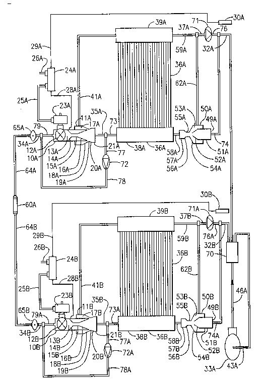
In the reversible heat pump system shown in FIG.
3, the fundamental components of FIG. 2 are arranged in a
unitary heat pump system with a bi-directional pulsed
ejector lOC made possible by bi-directional flow through a
valve element 12C-, which is actuated by a solenoid coil
23C.
Component parts in FIG. 3 with the same reference
numerals as in FIG. 1 and FIG. 2 function in an analogous
fashion as in those other embodiments. Suffixes C and D are
used here in FIG. 3 for parts corresponding to the numerals
with A and B suffixes in FIG. 2.
The critical element that makes the FIG. 3
embodiment into a reversible unitary heat pump is a bi-
directional flow through valve element 12C. This enables a
reversing valve 70A to change the direction of fluid flow
through the system without the need for check valves. In
one operating mode, for example, the 'cooling' mode, a bi-
directional pulsed ejector lOC meters refrigerant flow in
one direction, from the condenser heat exchanger 36D into
the evaporator heat exchanger 36C, actuated by the self-
regulating setpoint switch 24C. In the other operating
mode, for example, the 'heating' mode, the bi-directional
pulsed ejector lOC meters refrigerant flow in the opposite
direction, from the condenser heat exchanger 36C into the
88~9
_
evaporator heat exchanger 36D, actuated by the self-
regulating setpoint switch 24D. The respective heating and
cooling mode refrigerant flows are switched by the
reversing valve 70A.
In FIG. 3, the purpose of the check valve 71B and
the check valve 71C is to route refrigerant so that the
heat exchanger 36C and the heat exchanger 36D become
'bottom feed', or~'lower header feed' condensers, with
refrigerant entering the lower header first.
In ~IG. 3, a condenser overfeed ejector could be
installed in either the 'top feed' or 'bottom feed'
placements as described in FIG. 1 and FIG. 2. For overall
simplicity, the condensers could be piped as 'top feed',
which would enable the removal of the check valves 71B and
71C, and the connecting conduits 74C, 37C, 76B, and 74D,
37D, 76C as well. The spirit of FIG. 1, FIG. 2, and FIG. 3
is to show representative piping schematics, including
condenser overfeed ejectors, that can be further simplified
or augmented as required by circumstance. In each figure,
the condensers can be piped as 'top feed' or 'bottom feed'
as required. `
In the 'cooling mode,' as the bi-directional
pulsed ejector lOC alternates between fully open and fully
closed conditions, fluid alternately flows and does not
flow within the thermodynamic system. With each pulse, a
high velocity burst of fluid flows from the conduit 35C
into the lower header 38C of the evaporator heat exchanger
-- ~158~99
,.
36C. When the valve element 12C is open, suction within
the pulsed ejector suction port 17Cpulls refrigerant from
the upper header 39C of the evaporator 36C through the
ejector suction conduit 41C to the ejector suction port
17C. When the valve element 12C is closed the compressor
33Bpulls refrigerant in the reversed direction out of the
ejector suction port 17C through the conduit 41C back to
the inlet of the compressor 33B. Similar flow reversal and
secondary ejector effects within the heat exchanger 36C
occur as described with respect to the heat exchanger 36A
in FIG. 2.
Refrigerant flows out of the evaporator 36C from
the conduit 74C and the conduit 37C. Refrigerant from the
conduit 37C flows through the check valve 71B to the
conduit 76B. Refrigerant flow from the conduit 76B and the
conduit 74C combines to flow through the conduit 32C.
Refrigerant from the conduit 32C flows to the reversing
valve 70A. Refrigerant flows from the'reversing valve 70A
through the conduit 43B to the compressor 33B.
The compressor 33B transfers mechanical energy to
the fluid, increasing the pressure and temperature of-the
fluid and discharging it through the conduit 48B to the
reversing valve 70A. High pressure, high temperature
refrigerant leaving the reversing valve 70A through the
conduit 32D to the conduit 76C is prevented from entering
the upper header 39D of the condenser 36D by the check
valve 71C, resulting in the flow of refrigerant through the
36
~;1 1 r~ ~ ~S !3 ~3
__
conduit 74D to the lower header of the condenser 36D. When
the condenser 36D is fabricated as a completely parallel
heat exchanger with upper and lower headers, the condensing
process is similar to that described for the condenser 36B
of FIG. 2.
~ luid flows out of the condenser heat exchanger
36D through the conduit 35D. Refrigerant from the conduit
35D flows backwards through the ejector body llD which
consists of sections 21D, 20D, l9D, 18D and 17D, and
backwards through the ejector nozzle which consists of 16D,
15D and 14D, until the flow reaches the valve-nozzle
transition section 13D. When the valve element 12C opens,
fluid from the valve-nozzle transition section 13D flows
through valve element 12C to the valve-nozzle transition
section 13C. The pulse of fluid flows through the nozzle
and the ejector body into the evaporator 36C as previously
described.
To switch between 'cooling mode' and 'heating
mode!' the reversing valve 70A is actuated. When the heat
exchanger 36C functions as an evaporator, the self-
regulating setpoint switch 24C actuates the bi-directional
pulsed ejector lOC. When the heat exchanger 36D functions
as an evaporator, self-regulating setpoint switch 24D
actuates the bi-directional pulsed ejector lOC.
To accomplish the rapid hot gas defrost, a rapid
defrost switch 80 transfers electrical power from the
conduit 26E to the conduit 25E which transfers power to
21~8899
actuate reversing valve 70A to reverse the direction of
refrigerant flow. This reversal of flow sends hot gas to
what was previously the evaporator, to accomplish the
defrosting of the heat exchanger. When the defrosting is
substantially completed the rapid defrost switch 80
actuates the reversing valve 70A to return to the prior
flow direction, allowing the defrosted heat exchanger to
resume function as an evaporator.
flows and does not flow within the thermodynamic system.
With each pulse, a high velocity burst of fluid flows from
the conduit 35D into the evaporator heat exchanger 36D.
When the valve element 12C is open, suction within the
pulsed ejector suction port 17D pulls refrigerant from the
upper header 39D of the evaporator 36D through the ejector
suction conduit 4 lD to the ejector suction port 17D. When
the valve element 12C is closed the compressor 33B pulls
refrigerant in the reversed direction out of the ejector
suction port 17D through the conduit 41D back to the inlet
of the compressor 33B. Similar flow reversal and secondary
ejector effects within the heat exchanger 36D occur as
described with respect to the heat exchanger 36A in FIG. 2.
Refrigerant flows out of the -
evaporator 36D from the conduit 74D and the conduit 37D.
Refrigerant from the conduit 37D flows through the check
valve 71C to the conduit 76C. Refrigerant flow from the
conduit 76C and the conduit 74D combines to flow through
the conduit 32D. Refrigerant from the conduit 32D flows to
38
2158~99
the reversing valve 70A. Refrigerant flows from the
reversing valve 70A through the conduit 43B to the
compressor 33B.
The compressor 33B transfers mechanical energy to
the fluid, increasing the pressure and temperature of the
fluid and discharging it through the conduit 48B to the
reversing valve 70A. High pressure, high temperature
refrigerant leaving the reversing valve 70A through the
conduit 32C to the conduit 76B is prevented from entering
the upper header 39C of the condenser 36C by the check
valve 7lB, resulting in the flow of refrigerant through the
- conduit 74C to the lower header 38C of the condenser 36C.
When the condenser 36C is fabricated as a completely
parallel heat exchanger with upper and lower headers, the
condensing process is similar to that described for the
condenser 36B of FIG. 2.
Fluid flows out of the condenser heat exchanger
36C through the conduit 35C. Refriger~nt from the conduit
35C flows backwards through the ejector body llC which
consists of the sections 21C, 20C, l9C, 18C and 17C and
backwards through the ejector nozzle which consists of the
sections 16C, 15C and 14C until the flow reaches the valve-
nozzle transition section 13C. When the valve element 12C
opens, fluid from the valve-nozzle transition section 13C
flows through the valve element 12C to the valve-nozzle
transition section 13D. The pulse of fluid flows through
39
'~158~9
._ . .
the nozzle and the ejector body into the evaporator 36D as
previously described.
As the thermodynamic system functions as a
mechanical feedback loop, when the heat exchanger 36C
functions as an evaporator, the self-regulating setpoint
switch 24C will self-regulate the pressure and temperature
setpoints at the valve-nozzle transition section 13C and
the thermostatic ~ulb 30C to maintain the differential
pressure between the conduit 29C and the conduit 28C which
can be related to a thermodynamic superheat.
As the thermodynamic system functions as a
mechanical feedback loop, when the heat exchanger 36D
functions as an evaporator, the self-regulating setpoint
switch 24D will self-regulate the pressure and temperature
setpoints at the valve-nozzle transition section 13D and
the thermostatic bulb 30D to maintain the differential
pressure between the conduit 29D and the conduit 28D which
can be related to a thermod~namic supe~heat.
In the reversible heat pump system shown in FIG.
4, the fundamental components of FIG. 2 are arranged in a
unitary heat pump system with a single pulsed ejector lOD
and two reversing valves, 70B and 70C. The reversing valve
70B switches the compressor 33C hot gas discharge flow to
the heat exchanger 36E or to the heat exchanger 36F
depending on the mode of operation. The reversing valve
70C switches pulsed ejector discharge flow to the heat
exchanger 36F or to the heat exchanger 36E depending on the
~0
~15~99
~ .
mode of operation. Thus a sinqle pulsed ejector can be
utilized in a reversible heat pump circuit. Any liquid
refrigerant returning to a suction accumulator 82 is
recirculated through the heat exchanger acting as an
evaporator due to suction flow from the pulsed ejector lOD.
The valve element 12D of the pulsed ejector lOD is actuated
by the solenoid coil 23D.
Component parts 24E, 25F, 26F, 28E, 29E, 30E and
llE of EIG. 4, function in an analogous fashion to the
corresponding component parts 24B, 25B, 26B, 28B, 29B, 3OB
and llB, respectively, of FIG. 2.
Other component parts in FIG. 4 with the same
reference numerals as in FIG. 1 function in an analogous
fashion as in FIG. 1.
In one operating mode, for example, the 'cooling'
mode, the pulsed ejector lOD meters refrigerant flow
through the conduit 37E to the reversing valve 70C.
Refrigerant from the reversing valve 70C flows through the
conduit 73E into the evaporator heat exchanger 36E.
Refrigerant leaving the evaporator 36E through the conduit
32F enters the reversing valve 70B. Refrigerant entering
the reversing valve 70B from the conduit 32F leaves the
reversing valve 70B through the
conduit 83. The thermostatic bulb 30E senses the
temperature of the refrigerant within the conduit 83.
Refrigerant from the conduit 83 flows into the suction
accumulator 82.
f~ 1
~158~9
phase leaves suction accumulator 82 through the conduit 43C
to enter the compressor 33C. Compressed refrigerant leaves
compressor 33C through the conduit 48C to enter the
reversing valve 70B. Refrigerant entering the reversing
valve 70B from the conduit 48C leaves the reversing valve
70B through the conduit 32E. Refriqerant from the conduit
32E enters the condenser heat exchanger 36E. Refrigerant
leaves the condenser 36F through the conduit 73F to enter
the reversing valve 70C. Refrigerant entering the
reversing valve 70C from the conduit 73F leaves the
reversing ~ralve 70C through the conduit 34C to enter pulsed
ejector lOD. _
Liquid or vapor refrigerant from the suction
accumulator 82 leaves through the conduit 4lE due to the
suction action of the pulsed ejector suction port 17E. An
optional check valve may be placed within the conduit 4lE
to prevent refrigerant liquid from reversing direction and
flowing from the ejector suction port 17E through the
conduit 4lE back into the accumulator 82.
The conjunction of bulb temperature 30E and
system pressure at 13E determines the actuation of the
pulsed ejector lOD for metering refrigerant into the
evaporator 36E from the condenser 36E.
In the other operating mode, for example, the
'heating' mode, the pulsed ejector lOD meters refrigerant
flow through the conduit 35E to the reversing valve 70C.
Refrigerant from the reversing valve 70C flows through the
4~
~a~
conduit 73F into the evaporator heat exc~hanger 36F.
Refrigerant leaving the evaporator 36F through the conduit
32E enters the reversing valve 70B. P<efrigerant entering
the reversing valve 70B from the conduit 32E leaves the
reversing valve 70B through the conduit 83. The
thermostatic bulb 30E senses the temperature of the
refrigerant within the conduit 83. Refrigerant from the
conduit 83 flows into the suction accumulator 82.
Refrigerant in the vapor phase leaves suction accumulator
82 through the conduit 43C to enter the compressor 33C.
Compressed refrigerant leaves the compressor 33C through
the conduit 48C to enter the reversing valve 70B.
Refrigerant entering the reversing valve 70B from the
conduit 48C leaves the reversing valve 70B through the
conduit 32F. Refrigerant from the conduit 32F enters the
condenser heat exchanger 36E. Refrigerant leaves the
condenser 36E through the conduit 73E to enter the
reversing valve 70C. Refrigerant entering the reversing
valve 70C from the conduit 73E leaves the reversing valve
70C through the conduit 34C to enter the pulsed ejector
lOD.
The conjunction of bulb temperature 30E and
system pressure at 13E determines the actuation of the
pulsed ejector lOD for metering refrigerant into the
evaporator 36F from the condenser 36E.
Recirculation of liquid refrigerant from suction
accumulator 82 through an evaporator heat exchanger enables
43
339~
the liquid refrigerant to evaporate and provide cooling
capacity for the system.
When necessary, rapid defrosting may be
accomplished by switching from heating mode to cooling mode
for the duration of the defrost cycle, and then switching
back to heating mode. Condenser overfeed ejectors and
associated piping can be added as required.
The part load refrigerant storage system shown in
~IG. S is a result of the ability of pulsed metering
devices to effectively meter refrigerant of any quality;
subcooled liquid, saturated liquid, two phase, and vapor.
The purpose of the part load refrigerant management system
is to vary the cooling capacity of a system by varying the
quality of the refrigerant leaving the condenser by varying
the active refrigerant charge within the system. The
cooling capacity in the evaporator is relative to the
condenser leaving liquid quality, with the most cooling
capacity for subcooled liquid, less for saturated liquid,
less for two phase, and less for vapor.
In a typical system, one charges the system until
there is subcooled liquid present leaving the condenser.
This is accomplished by adding refriqerant charge until a
liquid line sight glass is full, and the liquid temperature
is below the saturation temperature of the liquid pressure,
indicatinq thermodynamic subcooling. A superheat
measurement is made at the evaporator outlet for the
desired saturation evaporator temperature, in order to
~4
133~
determine whether there is sufficient cooling capacity. In
order to lower superheat and increase cooling capacity,
more refrigerant charge is added to the system to increase
the condenser subcooling. In order to raise the superheat
and decrease cooling capacity, refrigerant is removed from
the system to decrease the condenser subcooling.
In the expansion systems of the prior art, a
"liquid seal" at the expansion device inlet is typically
required, which requires some degree of liquid subcooling
as a result. Thus the removal of refrigerant charge to
decrease cooling capacity at low load is not practical,
lest saturated or two phase refrigerant enter the expansion
device causing faulty system operation. As a result,
refrigeration systems of the prior art have difficulty
operating at low load conditions effectively, often
utilizing inefficient means of false loading the compressor
such as hot gas bypass, where hot gas is bypassed from the
compressor outlet directly back to the compressor inlet,
forcing the compressor to do pumping work without doing any
cooling with the bypassed flow. The other method of
lowering load is to reduce the evaporator pressure, and
thus temperature. This can lead to dropping the evaporator
temperature below 32 F, resulting in frosting over, and
blockage of the evaporator, which can lead to compressor
failure due to excessive liquid floodback. In compressors
that have performance curves that are very sensitive to
suction pressure and density, such as centrifugal
~lS8~9
~i,,j. .
compressors, going to lower load conditions by lowering
evaporator pressure can result in very poor efficiency and
performance at low loads.
The present ~nvention functions by bypassing
condenser outlet refrigerant into a reservoir when
evaporator outlet superheat drops, which lowers the
condenser pressure and liquid subcooling by removing
refrigerant charge~from the active system loop. As
necessary due to low load and low superheat, rerigerant
can be bypassed into the reservoir until the condensing
leaving refrigerant is two phase, and even just vapor,
resulting in lower cooling capacity in the evaporator. As
superheat rises, refrigerant from the reservoir is returned
to the active refrigerant system loop by entering the
evaporator, increasing the active refrigerant charge, which
increases the condenser pressure and lowers the quality of
the refrigerant leaving the condenser. Just as in charging
the system initially, the condenser leaving refrigerant
will go from vapor to two phase to saturated to subcooled,
as refrigerant is added to the active system loop. The
lower the quality of the condenser leaving refrigerant, the
higher the cooling capacity in the evaporator. Thus the
refrigerant bypass storage system manages low and high load
conditions by varying the quality of the refrigerant
leaving the condenser. As the pulsed ejector can
effectively meter any quality refrigerant, performance of
~6
~1 ~3~9
the overall system remains within required operating
realms.
In the embodiment of the refrigerant bypass
storage system shown in FIG. 5, the pulsed ejector lOE is
actuated by the pressure switch 24F. Electric power from
the conduit 26G enters the pressure switch 24F, and is
transferred through the conduit 25G to the solenoid coil
23E when the switch contacts within the pressure switch 24F
are closed, completing an electric circuit between the
conduit 26G, the pressure switch 24F, the conduit 25G, and
the solenoid coil 23E. When the switch contacts within the
pressure switch 24F are opened, breaking the electric
circuit between the conduit 26G, the pressure switch 24F,
the conduit 25G, and the solenoid coil 23E electric power
ceases to flow. Pressure switch 24F actuates the solenoid
coil 23E, which opens and closes the valve element 12E,
metering refrigerant flow to maintain a pressure setpoint.
The pressure switch 24F receives pressure information from
the system through the conduit 28F, which senses pressure
at the valve-nozzle transition section 13F. The pressure
switch 24F opens the valve element 12E on a drop in sensed
pressure below the pressure setpoint, and closes the valve
element 12E on a rise in sensed pressure above the pressure
setpoint. The opening and closing of the substantially
unrestricted valve element 12E causes high velocity pulsed
flow events through the valve body that are sensed by the
pressure switch 24F, resulting in a mechanical feedback
~7
~138~39
,.
loop self-regulation of pulse rate and flow to maintain the
pressure setpoint.
The pressure setpoint of the pressure switch 24F
can be, for example, the pressure at which the compressor
33D achieves optimum performance. As load variations
change, the pressure switch 24F will maintain the
evaporator pressure at the optimum point, and the
refrigerant bypass system will vary the condenser leaving
refrigerant quality based on evaporator outlet superheat,
effectively modulating evaporator cooling capacity.
Regulating system performance by refrige~ant bypass based
on a superheat determination is useful in that the
compressor requires a certain minimum superheat to avoid
damage, and the effective use of the evaporator surface
area depends on a minimum, regulated superheat. For
example, given that a means of providing superheat to the
evaporator outlet refrigerant is provided within the
system, the evaporator could be run with a fully wetted
surface area, increasing evaporator performance and cooling
capacity, increasing system performance with the compressor
still protected from damage by refrigerant liquid or wet
vapor. Load management with the refrigerant bypass
modulation of condenser leaving refrigerant quality
maintains the system performance and efficiency within
operating requirements as operating conditions vary.
In the refrigeration system, the practical
requirement of the refrigerant bypass system and bypass
4~
~13~
reservoir is to have sufficient refrigerant to return to
the active system at high loads, and sufficient volume to
store refriqerant at low loads. Most importantly, the
relative levels of refrigerant in the active system and in
the reservoir should be self-regulated to maintain optimum
system performance and efficiency as operating conditions
vary. This self-regulated balance can occur due to the
conjunction of a pressure switch for regulating evaporator
pressure and a superheat switch for regulating refrigerant
bypass into the reservoir. Other combinations of system
variables, such as pressure, temperature, superheat,
subcooling, and concentration, can be utilized to self-
regulate system operation and refrigerant bypass storage
and release.
In the part load refrigeration storage system
shown in FIG. 5, the thermostatic bulb 30F transfers
temperature information from the evaporator 36G outlet
conduit 32G to the superheat switch 24G through the conduit
29F., System pressure information is transferred to the
superheat switch 24G through the conduit 28G and the
conduit 85, which senses pressure at the valve-nozzle
transition element 13F. The superheat switch 24G can be
composed of a differential pressure switch acting on the
difference in pressure between the conduit 28G representing
system pressure and the conduit 29F representing pressure
within the thermostatic bulb 30F. The superheat switch 24G
acts to allow refrigerant to enter a bypass reservoir 86 on
49
215~89~
a drop in the sensed differential pressure, which can be
related to a drop in superheat, and acts to allow
refrigerant to leave the bypass reservoir 86 on a rise in
the sensed differential pressure, which can be related to a
rise in superheat.
On a rise in sensed superheat, electrical power
from the conduit 26H is transferred by the superheat switch
24G through the co~duit 25I to the solenoid coil 23G, which
opens the solenoid valve lOG, allowing refrigerant from the
bypass reservoir 86 to leave through a conduit 87, flow
through solenoid valve lOG, flow through a conduit 85 and
enter the active system loop through the valve-nozzle
transition element 13F. The solenoid valve lOF is closed.
On a drop in sensed superheat, electrical power
from the conduit 26H is transferred by the superheat switch
24G through the conduit 25H to the solenoid coil 23F, which
opens the solenoid valve lOF, allowing condensed
refrigerant from the conduit 90 to flow through the
solenoid valve lOF, through the conduit 91 and enter the
bypass reservoir 86. The solenoid valve lOG is closed.
As superheat rises and falls, refrigerant
alternately enters and leaves the reservoir 86, alternately
entering and leaving the active system circuit.
As the pressure switch 24F maintains evaporator
pressure, the superheat switch 24G maintains evaporator
superheat. The conjunction of the pressure switch 24F and
the superheat switch 24G act to handle load variations.
215~8!~9
In FIG. 5, components 33D, 48D, 61B, 64C, 65C,
34D and 79B function in an analogous fashion to the
corresponding component parts 33A, 48A, 61A, 64B, 65B, 34B
and 79A respectively, of FIG. 2. The condenser heat
exchanger 36H includes a lower header 38E, parallel
vertical tubes 40C and a dead-ended upper header 39E. It is
a 'bottom feed' condenser fed with hot gas from the conduit
48D, with condensed liquid leaving from the bottom header
through the conduit 59A. Hot superheated gas from the
compressor discharge enters the lower header 38E from one
end, rises into the tubes 40C, condenses, setting up an
internal turbulent counterflow of hot gas rising within the
tubes 40C and condensed liquid falling down the tube walls
to collect in the lower header 38E. As liquid fills the
lower header 38E the hot gas very rapidly de-superheats by
the intimate mixing process of bubbling through the
condensed liquid. Condensed, and even subcooled liquid
refrigerant leaves the lower header 38E through the conduit
59A at the end opposite to the hot gas inlet from the
conduit 48D with each high velocity pulse event.
The pulsed ejector lOE, ejector body llE, and
their component parts function in analogous fashion to the
pulsed ejector lOA, ejector body llA, and their component
parts of FIG. 2. The only substantial difference is that
the pulsed ejector lOE is actuated by the pressure switch
24F, whereas the pulsed ejector lOA is actuated by the
superheat switch 24A. The heat pump system in FIG. 2 will
2158~!~9
vary load by self-regulating superheat, and by raising and
lowering evaporator pressure and temperature as required.
The refrigeration system in FIG. 5 will vary load by self-
regulating at a relatively fixed evaporator pressure and
temperature.
In FIG. 6, the pulsed ejector lOH regulates the
flow of a refrigerant to an evaporator heat exchanger 36I
in which the refrigerant takes on heat from the environment
to be cooled. The refrigerant vapor then flows into an
absorber 93 where it is absorbed by thermodynamic fluid in
the liquid state, releasing heat energy in an exothermic
process to the ambient environment. A pump 94 pressurizes
the liquid from the absorber 93, pumping it through a
counter-flow heat exchanger 95 into a vapor generator 96.
The high pressure liquid in the vapor generator 96 absorbs
heat energy from a higher temperature ambient source,
releasing the refrigerant vapor absorbed into the liquid in
the absorber 93 as a high pressure and high temperature
vapor. The high pressure and high temperature refrigerant
vapor flows from the vapor generator 96 to a rectifier 97
which removes any water in the liquid or vapor phase from
the refrigerant vapor. In some applications the rectifier
97 is not required; for example, when water is the
refrigerant. The dry vapor leaving the rectifier 97
condenses into liquid refrigerant in the condenser heat
exchanger 44A which releases heat energy to the ambient
environn~ent. Liquid refrigerant from the condenser 44H
;~13~99
~ ,
flows to the inlet of the pulsed ejector lOH to complete a
thermodynamic cycle.
Liquid absorbent fluid from the vapor generator
96 flows back through a conduit 98 to the counter-flow heat
exchanger 95, where it exchanges heat energy with fluid
flowing from the pump 94 to the vapor generator 95, and
then through a conduit 99 to the pulsed ejector lOI which
opens and closes to meter absorbent fluid flow back to the
absorber 93.
temperature information, alternately opening and closing
the pulsed ejector lOH. The pulsed ejector lOH replaces a
throttling expansion valve in systems of the prior art.
Absorbent fluid continually cycles through its
system loop in an intermittent fashion as the differential
pressure switch 24J responds to internal pressure
information, alternately opening and closing the pulsed
ejector lOI. The pulsed ejector lOI replaces a throttling
metering valve in systems of the prior art.
' Both the pulsed ejector lOH and the pulsed
ejector
lOI recover energy wasted in the throttling devices of the
systems of the prior art. In systems where there are
additional throttling devices, the throttling devices can
be replaced with pulsed ejectors, or simple ejectors that
do not include actuated valve elements.
The pulsed ejector absorption refrigeration
system in FIG. 6 includes a condenser overfeed ejector 50C,
~i53g9~
the pulsed ejector lOH feeding the evaporator 36I and
p~oviding for recirculation, and the pulsed ejector lOI
feeding the absorber 93 and providing flow assist in moving
fluid from the evaporator 36I to the absorber 93.
The solenoid-actuated pulsed ejector lOH is
actuated by the solenoid coil 23J which fully opens the
valve element 12H when electrically energized and fully
closes the valve e~ement 12H when deenergized. The
superheat switch 24I regulates the energization and de-
energization of the solenoid coil 23J. The electrical
conduit 25K transfers electrical power between the electric
contacts of the superheat switch 24I and the solenoid coil
23J. The electrical conduit 26J supplies electrical power
to the solenoid coil 23J through the electric contacts of
the switch 24I and the electrical conduit 25K.
Electric power from the conduit 26J fully opens
the pulsed ejector lOH when the contacts of the switch 24I
complete an electrical circuit between 26J, 25K, and 23J.
When.the electrical circuit between them is broken by the
opening of the electrical contacts of the switch 24I, the
solenoid coil 23J is deenergized and the pulsed ejector lOH
returns to its normally closed condition.
The conduit 28H transfers pressure information
from within the valve-ejector transition section 13I to the
superheat switch 24I. The conduit 29I transfers pressure
information from within the thermostatic bulb element 30I
to the superheat switch 24I. The thermostatic bulb 30I
2 ~
senses system temperature at the evaporator outlet conduit
32I. The differential pressure at which the superheat
switch 24I is set to open the pulsed ejector lOH is chosen
by design criterion. Thermodynamic criterion other than
superheat can be utilized to the actuate pulsed ejector
lOH.
As the pump 94 lowers the pressure in the suction
side of the thermodynamic system, and heat energy is added
to the evaporator 36I, the superheat switch 24I opens the
pulsed ejector lOH when the differential pressure between
the bulb 30I pressure and the system pressure at the valve-
ejector transition section 13I, which can be related to a
superheat equivalent, rises above the differential pressure
setting of the superheat switch 24I, permitting flow of the
thermodynamic fluid from within the upstream system conduit
34E through the pulsed ejector lOH to the downstream system
conduit 35I.
As the high velocity burst of thermodynamic fluid
enteis the valve-ejector transition section 13I and flows
to the downstream conduit 35I it produces an internal
system pressure rise within the suction side of the system.
Refrigerant flowing through the evaporator 36I to the
outlet conduit 32I can lower the temperature as sensed by
the thermostatic bulb 30I, lowering its internal bulb
pressure.
When the differential pressure sensed by the
superheat switch 24I drops below the differential pressure
-
21~93
setpoint of the superheat switch 24I, the electric contacts
of the superheat switch 24I open and the solenoid coil 23J
deenergizes closing the valve element 12H within the pulsed
ejector lOH, and stopping thermodynamic fluid flow through
the pulsed ejector lOH.
With the pulsed ejector loH closed, the pump 94
lowers the suction side pressure, and heat addition to the
evaporator 36I can raise the temperature sensed at the
evaporator outlet conduit 32I by the thermostatic bulb 30I,
the differential pressure sensed by the superheat switch
24I rises above its differential pressure setpoint,
resulting in the reopening of the pulsed ejector lOH.
As the pulsed ejector lOH alternates between
fully open and fully closed conditions, refrigerant fluid
alternately flows and does not flow within the
thermodynamic system.
The pulsed ejector lOH component parts of FIG. 6
function in an analogous fashion to the corresponding
pulsed ejector 10 component parts of FIG. 1.
In FIG. 6, the ejector suction conduit 41G is
shown recirculating fluid from what can be construed to be
the upper header 39F of a parallel, vertical, evaporator
36I.
The high velocity burst of thermodynamic fluid
flows into the lower header 38I of the evaporator heat
exchanger 36I through the conduit 35I, resulting in
internal recirculation flows within evaporator 36I as
56
21~8~9
.. .
previously described. Fluid flows out of evaporator 36I
through the ejector suction conduit 32I to the ejector
suction port 17J of the pulsed ejector lOI. When the
pulsed ejector lOI is closed, refrigerant fluid from the
conduit 32I may still flow through the body of the pulsed
ejector lOI, flowing through the ejector suction port 17J,
the converging section 18J, the ejector throat/bore section
l9J, the diverging diffuser section 20J, the ejector outlet
section 21J, flowing through the conduit 35J to enter the
absorber 93.
~ efrigerant from the evaporator 36I is absorbed
by the liquid absorbent fluid within the absorber 93 in
what is typically an exothermic process, releasing heat
energy to the external environment. Liquid absorbent fluid
is pumped out of the absorber 93 through a conduit 100 by
pump 94.
The pump 94 raises the pressure of the liquid
absorbent fluid and discharges the pressurized liquid
thro~gh a conduit 101 to the counter-flow heat exchanger
95. Pressurized liquid absorbent fluid that enters the
counter-flow heat exchanger 95 through the conduit 101
leaves through a conduit 102 and enters the vapor generator
96. Heat energy from a higher temperature ambient
environment is transferred to the vapor generator 96 so
that refrigerant vapor is released from the absorbent fluid
in an endothermic process.
57
`~.
~ 215~99
The high pressure refrigerant vapor leaves the
vapor generator 96 through a conduit 103 and flows to the
rectifier 97 which functions as a desiccant to remove any
water in the liquid or vapor phase from the refrigerant
vapor. Dry refrigerant vapor leaves the rectifier 97
through a conduit 104 and enters a simple condenser
overfeed ejector SOC prior to entering the condenser heat
exchanger 44A.
In FIG. 6, simple pulsed ejector SOC and its
component parts function in an analogous fashion to simple
pulsed ejector S0 and component parts in FIG. 1. Discharge
flow from simple pulsed ejector 50C flows through conduit
58C to the upper header 39G of condenser heat exchanger
44A.
The ejector suction conduit 62C is shown
recirculating fluid from what can be construed to be the
lower header 45A of a parallel, vertical, condenser 44A.
Dry refrigerant vapor within the condenser heat
exchSnger 44A changes thermodynamic state to refrigerant
liquid as it releases heat energy to heat the external
environment. Liquid refrigerant leaves the condenser 44A
through the conduit 34E and flows to the inlet of the
pulsed ejector lOH to complete a thermodynamic cycle.
High pressure liquid absorbent fluid from the
vapor generator 96 leaves through the conduit 98 and flows
through the counter-flow heat exchanger 95, where it
transfers heat energy to absorbent fluid flowing from the
~ 3~
pump 94 to the vapor generator 96, preheating the absorbent
fluid before it enters the vapor generator 96. Liquid
absorbent fluid entering the counter-flow heat exchanger 95
through the conduit 98 leaves the counter-flow heat
exchanger 9S through the conduit 99 and flows to the inlet
of the pulsed ejector lOI.
The pulsed ejector lOI opens and closes to meter
absorbent f1uid flow back to the absorber 93, with the
pulsed suction flow assisting the pump in moving fluid from
the evaporator 36I to the absorber 93.
The solenoid-actuated pulsed ejector lOI is
actuated by the solenoid coil 23K which fully opens the
valve element 12I when electrically energized and fully
closes the valve element 12I when deenergized. The
differential pressure switch 24J regulates the energization
and de-energization of the solenoid coil 23K. The
electrical conduit 25L transfers electrical power between
the electric contacts of the differential switch 24J and
the s~lenoid coil 23K. The electrical conduit 26K supplies
electrical power to the solenoid coil 23K through the
electric contacts of the switch 24J and the electrical
conduit 25~.
Electric power from the conduit 26K fully opens
the pulsed ejector lOI when the contacts of the switch 24J
complete an electrical circuit. When the electrical
circuit is broken by the opening of the electrical contacts
~ 2 1 ~
the solenoid coil 23K is deenergized and the pulsed ejector
lOI returns to its normally closed condition.
The basic premise of the self-regulated pulsed
actuation of the absorbent flow pulsed ejector lOI is as
follows:
With the pulsed ejector lOH and pulsed ejector
lOI normally closed, the pump 94 acts to lower the pressure
within the suction side of the system, seeking to maintain
an evaporator pressure and temperature as self-regulated by
the superheat switch 24I as it meters refrigerant flow. The
pulsed ejector lOI has the active criterion of metering
absorbent fluid flow back to the absorber, at the absorber
pressure that is fundamentally determined by the superheat
switch 24I. With the expectation of a minimal amount of
pressure drop from the evaporator to the absorber, pulsed
ejector lOI has the active criterion of metering absorbent
fluid back to the absorber at a pressure slightly lower
than the evaporator pressure.
Take, for example, a pressure difference of 1
PSIA, pounds per square inch absolute, between the
evaporator and the absorber; with the evaporator 1 PSIA
higher than the absorber. To maintain this, one places the
differential pressure switch 24J in communication with the
evaporator pressure, in communication with the absorber
pressure, and in communication with the absorber pulsed
ejector lOI.
-
215~9
The conduit 28I transfers pressure information
from within the valve-ejector transition section 13J,
sensing absorber inlet pressure, to the differential
pressure switch 24J. The conduit 29J transfers pressure
information from within the valve-ejector transition
section 13I, sensing evaporator inlet pressure, to the
differential pressure switch 24J.
The differential pressure at which the
differential pressure switch 24J is set to open the pulsed
ejector lOI is chosen by design criterion. Thermodynamic
criterion other than differential pressure may be utilized
to actuate the pulsed ejector loI. For example, a
differential pressure switch seeking to maintain discharge
side pressures, such as condenser outlet pressure and
absorbent pressure at the inlet of absorbent pulsed ejector
lOI.
As the pump 94 lowers the pressure in the suction
side of the thermodynamic system, and heat energy is added
to the evaporator 36I, the superheat switch 24I opens the
pulsed ejector lOH when the differential pressure between
the bulb 30I pressure and the system pressure at the valve-
ejector transition section 13I, which can be related to a
superheat, rises above the differential pressure setting of
the superheat switch 24I, permitting flow of the
thermodynamic fluid from the refrigerant discharge side of
the thermodynamic system through the pulsed ejector lOH to
the refrigerant suction side of the thermodynamic system;
61
producing an internal system pressure rise within the
suction side of the system.
The rise in pressure within the suction side of
the system is first noted at the valve-ejector transition
section 13I as it is the closest location to the mass
influx through the pulsed ejector valve element 12H. The
rise in suction pressure is thus sensed simultaneously by
the superheat switch 24I through the conduit 28H and sensed
by the differential pressure switch 24J through the conduit
29J.
When the differential pressure between the valve-
ejector transition section 13I and the valve-ejector
transition section 13J sensed by the differential pressure
switch 24J rises above the differential pressure setpoint
of the differential pressure switch 24J, the electric
contacts of the differential pressure switch 24J close and
the solenoid coil 23K energizes opening the valve element
12I within the pulsed ejector lOI, allowing thermodynamic
fluid flow through the pulsed ejector lOI.
Absorbent fluid flowing through pulsed ejector
lOI into the absorber 93 raises the absorber pressure, as
sensed by the differential pressure switch 24J through the
conduit 28I at the valve-ejector transition conduit 13J.
When the differential pressure between the valve-
ejector transition section 13I and the valve-ejector
transition section 13J sensed by the differential pressure
switch 24J drops below the differential pressure setpoint
62
~ 2i5~89g
of differential pressure switch 24J, the electric contacts
of the differential pressure switch 24J open and the
solenoid coil 23K deenergizes, closing the valve element
12I within the pulsed ejector lOI, and stopping absorbent
fluid flow through the pulsed ejector lOI.
As before, refrigerant flowing through the
evaporator 36I to the outlet conduit 32I can lower the
temperature as sensed by the thermostatic bulb 3OI,
lowering its internal bulb pressure.
When the differential pressure sensed by the
superheat switch 24I drops below the differential pressure
setpoint of the superheat switch 24I, the electric contacts
of the superheat switch 24I open and the solenoid coil 23J
deenergizes closing the valve element 12H within the pulsed
ejector lOH, and stopping refrigerant fluid flow through
the pulsed ejector lOH.
With the pulsed ejector lOH closed the pump 94
lowers the suction side pressure, and heat addition to the
evaporator 36I can raise the temperature sensed at the
evaporator outlet conduit 32I by the thermostatic bulb 30I,
the differential pressure sensed by the superheat switch
24I rises above its differential pressure setpoint,
resulting in the reopening of the pulsed ejector lOH.
With the pulsed ejector lOI closed the pump 94
lowers the suction side pressure within the absorber to
maintain the natural flow from evaporator to absorber, ~.
resulting in a drop in the differential pressure sensed by
63
`-~ 2 ~ 3 ~ 9
the differential pressure switch 24J below its differential
pressure setpoint, resulting in the reopening of the pulsed
ejector lOI.
As the pulsed ejector lOH alternates between
fully open and fully closed conditions, refrigerant fluid
alternately flows and does not flow within the
thermodynamic system.
As the pulsed ejector lOI alternates between
fully open and fully closed conditions, absorbent fluid
alternately flows and does not flow within the
thermodynamic system.
The high velocity pulse mass flow flowing through
absorbent fluid pulsed ejector valve element 12I flows
through the valve-ejector transition section 13J, through
the ejector body llJ which entails flow through the ejector
nozzle 14J, the ejector converging section 18J, the ejector
throat/bore section l9J, the ejector diverging diffuser
section 20J, the ejector outlet section 21J through the
cond~it 35J into the absorber 93.
High velocity pulse flow through the ejector
nozzle 14J transfers momentum to fluid within the ejector
suction port 17J, which draws refrigerant from the
evaporator 36I through the ejector suction conduit 32I.
The high velocity absorbent fluid flow and the entrained
refrigerant flow from the suction port 17J combine to flow
through the ejector sections 18J, l9J and 20J which
function to recover some of the combined flow velocity as a
64
~15~9~
pressure rise. The pressure rise achieved lowers the
pumping pressure rise requirement of the pump 94 as the
pulsed ejector lOI helps the pump move refrigerant flow
from the evaporator to the absorber.
The combined flow leaves the ejector body llJ
through the ejector outlet section 21J, flowing through the
conduit 35J to the absorber 93. The absorption process
within the absorber~93 is generally exothermic as
refrigerant vapor is absorbed by absorbent fluid. The high
velocity pulsed flows and the inherent mixing within the
ejector body llJ can be a means of improving absorber
performance.
Absorbent fluid leaves the absorber 93 through
the conduit 100 in a state of relatively higher absorbed
refrigerant concentration than the fluid entering pulsed
ejector lOI. The higher concentration absorbent fluid is
returned to the pump 94 by the conduit 100 to continue the
thermodynamic cycle.
! The pulsed ejector absorption refrigeration
system shown in FIG. 7 differs from that shown in ~IG. 6 in
the relative orientations of the ejectors relative to the
heat exchangers and the absorber. The pulsed ejector
absorption refrigeration system in FIG. 7 includes a
condenser overfeed ejector 50E, a pulsed ejector loJ
feeding the evaporator 34L and providing for recirculation
of refrigerant, and a pulsed ejector lOK feeding the
21~8~99
~ .
absorber 88A and providing for recirculation of absorbent
fluid.
The evaporator outlet conduit 32J in FIG. 7 is
analogous to the evaporator outlet conduit 32I in FIG. 6
except that the evaporator outlet conduit 32J transfers
refrigerant directly to the absorber 88A, as opposed to the
case in FIG. 6 where the evaporator outlet conduit 32I
transfers refrigerant directly to the pulsed ejector loI
prior to entering the absorber 88.
In FIG. 7 the pulsed ejector suction conduit 41L,
serves to recirculate absorbent fluid leaving the absorber
93A through the conduit lOOA. In contrast in FIG. 6 the
pulsed ejector suction conduit 32I, serves to assist the
pump 94 in providing refrigerant flow from the evaporator
36I to the absorber 93.
The spirit of the difference between the
embodiments of FIG. 6 and FIG. 7 with respect to the
absorber pulsed ejector is the following:
! The pulsed ejector lOI in FIG. 6 is in a series
orientation with respect to the absorber 93 and the pump 94
so that the pulsed ejector provides a partial pressure rise
to the refrigerant prior to entering the absorber. The
pulsed ejector lOK in FIG. 7 is in a parallel orientation
with respect to the absorber 93A and the pump 94A so that
the pulsed ejector provides an increased flow rate within
the absorber 93A by recirculatinq absorbent fluid through
the absorber 93A.
- 213~9
~ ._
The pulsed ejector lOK in FIG. 7 may have its
ejector suction conduit 41L attached at any point within
the absorber 93A, accomplishing recirculation of absorbent
fluid. In FIG. 7 the component parts with the same
numerical prefix as the component parts in FIG. 6 function
in an analagous fashion, respectively. The aforementioned
component parts of FIG. 6 and FIG. 7 differ in their
alphanumeric suffixes, respectively.
In FIG. 7 the ejector suction conduit 41K is
shown recirculating fluid from what can be construed to be
the lower header 38J of a parallel, vertical, evaporator
36J. The ejector suction conduit 62D is shown recirculating
fluid from what can be construed to be the upper header 39I
of a parallel, vertical, condenser 44B.
The simple pulsed condenser overfeed ejector 50D
communicates fluid flow through conduit 58D to the lower
header 45B of the parallel, vertical condenser 44B, causing
internal recirculation flow as previously described.
The pulsed ejector lOJ communicates fluid flow
through conduit 35K to the upper header 39H of the
parallel, vertical evaporator 36J, causing internal
recirculation flow as previously described.
Anticipating pulsed flow reversal phenomenon
within the ejector suction recirculation conduit 41L in
FIG. 7, a check valve may be placed within that conduit to
prevent reversed flow from the ejector suction port 17L
back to the pump 94A through the conduit lOOB.
~1~33~9
In the spirit of the invention, the relative
communication of the ejectors to the heat exchangers in can
be in any combination of 'top feed', 'bottom feed',
'parallel', and 'series'. In the event that the heat
exchangers utilized in a particular embodiment do not have
headers, the relative communication of the ejectors to the
heat exchangers can be in any combination of 'parallel' and
'series' with respect to the means provided to increase the
pressure of and provide flow to the thermodynamic fluid
within the thermodynamic system.
The non-steady-state intermittent flow through
the nozzling devices in the present invention is a
substantially isentropic nozzling process. The flow
process through the throttling valves in steady-state
systems of the prior art is a substantially isenthalpic
throttling process. In a throttling device there is a
distinct means of flow restriction that results in fluid
flow losses and a generation of entropy while providing a
pressure drop to steady-state flow. The flow restriction
results in a negligible velocity increase as fluid
experiences a drop in pressure and temperature in what is
modeled thermodynamically as a constant enthalpy Joule-
Thomson throttling expansion process. The Joule-Thomson
expansion process is the classical basis of steady-state
refrigeration, heat pump and air-conditioning cycles.
The nozzling devices are either fully open or
fully closed with no intermediate positions, with minimal
68
~ 1~8g~3
flow restriction in the fully open condition. The absence
of flow restriction results in a substantially isentropic
nozzling flow process and a substantial fluid velocity
increase as fluid experiences non-steady-state flow and a
pressure drop. The pressure difference between the inlet
and the outlet of a nozzling device occurs when fully
closed. Inlet and outlet system pressures tend towards
equalization when the nozzling devices are fully open.
Slight flow losses and small departures from ideal
isentropic flow through the nozzling devices are to be
expected, but not to the extent to which throttling devices
are designed to produce flow restrictions.
Both pressure and enthalpy are transferred to
kinetic energy as fluid flows through a nozzling device.
Flow increases to subsonic, sonic, and supersonic
velocities depending on operating conditions and nozzle
design as thermodynamic entropy remains substantially
constant. The isentropic nozzling expansion process, with
the corresponding drop in pressure, temperature, and
enthalpy, and the increase in velocity is the basis of non-
steady-state refrigeration, heat pump, and air-conditioning
cycles.
The utilization of the high velocity pulsed flows
as a means to transfer momentum and provide flow to
thermodynamic fluid within the system is within the scope
of this invention, including but not limited to the
incorporation of ejectors and suitably designed heat
69
-' ~1 j8~9~
exchangers that experience internal recirculation flows as
aresult of the high velocity pulsed flows.
The scope of the invention is to be determined
from the following claims rather than the foregoing
description of certain preferred embodiments.