Note: Descriptions are shown in the official language in which they were submitted.
w 095/20820 21 ~ ~ 9 ~6 1 PCT~E95/00009
Title of the Invention
COMPOSITIONS AND METHODS FOR PROVIDING ANISOTROPIC CONDUCTIVE
PATHWAYS AND BONDS BETWEEN TWO SETS OF CONDUCTORS
Technical Field
This invention relates to compositions and methods for
providing anisotropic conductive pathways between two sets of
conductors, and to compositions and to methods for making
anisotropically-conductive bonds between two conductors. The
invention is particularly for use in the electronics industry.
Backqround Art
Electronic components such as semiconductor chips are often
very small and have minimal gaps between connectors such as pins.
Conventional solder may give rise to difficulties because the solder
may bridge the gap between two pins. Therefore anisotropically
-conductive adhesives have been proposed for electrical
interconnection. An anisotropically conductive adhesive (ACA)
conducts electricity in one direction only (usually denoted as the Z
direction) and should eliminate conduction in the plane
perpendicular thereto (the X and Y directions).
Various proposals for ACA's are reviewed by Ogunjimi et al. in
Journal of Electronics Manufacturing (1992) 2, 109 - 118. They
usually consist of an adhesive matrix in which conductive particles
are dispersed. The particles may be metal particles, or
non-conductive particles (e.g. plastic or glass) with a thin metal
WO 9~/20820 PCT/IE95/00009
'h~5~ - 2 -
coat. After the adhesive has been applied between two conductors,
bond line thickness may then be reduced by pressure applied during
cure so that the particles in the adhesive contact the two
conductors but do not contact one another laterally (see U.S. Patent
4,740,657 Tsukagoshi et al.). Alternatively, conductive particles
which are also magnetic may be aligned by use of a magnetic field so
that they form a chain and provide an anisotropically conductive
path along the direction of the field. The adhesive is then cured
while the field is applied (see U.S. Patents 3,359,145 Salyer et al;
4,548,862 Hartman; 4,644,101 Jin et al; and 4,170,677 Hutcheson).
U.S. Patent 4,737,112 Jin et al. uses single-particle bridging with
essentially uniform distribution resulting from application of a
magnetic field. Particles are magnetized N-S by the magnetic field,
resulting in lateral repulsion between particles. The text at
column 4 lines 6 - 8 suggests that the particles may have a
non-magnetic, non-conductive core portion which is coated with a
magnetic conductive coating. However no working Examples of the use
of such particles are described. The Examples in the Jin et al.
patent use gold coated nickel spheres which would have a solid core
of magnetic material.
In an unrelated area of technology, it is known to make a
magnetic liquid or "ferrofluid" consisting of a colloidal suspension
of minute ferromagnetic particles in an non-magnetic carrier
liquid. A typical ferrofluid may consist of magnetite particles
(Fe304) having a particle size in the range 2 nanometres to 0.1
micrometres (and a mean size of about 0.01 micrometres) in kerosene
as carrier liquid with a surfactant to prevent agglomeration of the
particles (see Skjeltorp "One- and Two-Dimensional Crystallization
of Magnetic Holes" in Physical Review Letters, Volume 51, Number 25,
19 December 1983, 2306-2309, the contents of which are incorporated
by reference). Skjeltorp describes the production of "magnetic
holes" inside a thin layer of magnetic fluid containing a monolayer
of polydisperse polystyrene spheres with diameters in the micrometre
range. U.S. Patent No. 4 846 988 (Skjeltorp) describes a method for
bringing bodies immersed in liquid to form regular structural
patterns by dispersing non-magnetic, essentially monodisperse,
particles having uniform sizes and shapes in a ferrofluid so that
WO 95120820 PCT/IE95/00009
2~89~
the particles create non-magnetic "holes" in the ferrofluid, and
applying a substantially homogeneous magnetic field to the
ferrofluid. Each of the dispersed non-magnetic particle bodies then
assumes a magnetic moment corresponding to the volume of liquid
displaced by the body, but inversely directed. Magnetic interaction
forces then prevail between the particle bodies, which may thus be
collectively controlled by the external magnetic field to assume
structural patterns. When the particle bodies are relatively large
(greater than or equal to 5 micrometres) compared to the size of the
magnetite particles (of the order of 0.01 micrometres) within the
ferrofluid, they undergo negligible Brownian motion. However when
the particles are smaller than about one micrometre, Brownian motion
introduces fluctuations into the system which can prevent the build
up of very long chains and cause chain pieces to reptate (Skjeltrop
A.T. and Helgesen, G. Phyisica A, 176, 37, 1991; Skieltrop A.T. J.
Appl. Physics 57(1), 3285, 1985). Nevertheless with small particle
body inclusions it is still possible to develop longer and stiffer
chains by increasing the magnetic field. The utility of Skjeltrop's
invention in U.S. 4,846,988 is to form patterns which may influence
electromagnetic and acoustic waves, simulate states and processes in
atomic or molecular structures and the like. Skjeltorp states that
the non-magnetic particle bodies are mondisperse bodies (i.e. a
great number of bodies have essentially identical size and form) and
are preferably made of plastic material, in particular polystyrene.
There is no suggestion of using electrically conductive particle
bodies.
Neither is there a suggestion that pure noble metal colloids,
with particle sizes comparable to those of the magnetic material
itself, can be used to form anisotropic structural patterns made up
of metallic pathways by first using magnetic field induced
aggregation of the noble metal and second aligning said aggregates.
It is known, for example, that gold and other noble metals can be
made in colloidal form in an aqueous or non-aqueous state (Nakao Y.,
J Chem Soc Chem Commun., 826, 1993; Nakao, Y. and Kaeriyama K.,J.
Colloid Interface Sci., 110(1), 82, 1986), and that colloidal metal
particles may be dispersed in polymerisable systems such as
acrylics, styrenes and acrylonitrile (Cardenas-Trivino G. et al.,
WO 95/20820 PCT/IE95/00009
~ ~ 3 ~39 4 ~ -
Chemistry of Materials, 1, 481, 1989, Polymer Bulletin 27, 383,
1992, Polymer Bulletin 26, 611, 1991, Polymer Bulletin 31, 23, 1993;
Nakao et al. loc cit.). Still further, it is known to be possible
to produce so-called ferrofluid composites, which differ from stable
co-colloidal systems but none the less comprise minute metallic
components which align in response to a magnetic field (Popplewell,
J. et al. J.Magnetism & Magnetic Materials, 54-57, 761, 1986; see
also Kopcansky, P., et al. Acta Phys Slov. 39(4), 259, 1989). The
latter systems have been proposed as possible polarisers or
attenuators for microwave (3mm wavelength range) radiation. There
has been no suggestion in the literature that such systems could be
rendered permanent following the removal of the magnetic field. The
possibility that co-colloidal systems could undergo magnetic field
induced phase separation followed by alignment of metal aggregates
in structural patterns which can be subsequently locked permanently
in position and be used as an anisotropically conductive adhesive,
has not been suggested.
U.S. Patent 5,075 034 Wanthal describes a two component
adhesive composition which is curable by induction heating (i.e.
with an induced magnetic field) and which contains conductive carbon
black along with iron oxide particles. However there is no
suggestion that the iron oxide particles may be of such small
particle size as to form a colloidal suspension. This patent
therefore does not relate to the field of ferrofluids or of
anisotropically conductive adhesives.
In a further unrelated area of technology, U.S. Patent No.
4,946,613 Ishikawa describes a photosetting ferrofluid for use in
magnetic flaw detection or for visualising magnetically recorded
patterns. The photosetting ferrofluid comprises a carrier, a
ferrofluid in which the ferromagnetic particles have an adsorbed
surfactant (or the surfactant is dispersed in the carrier) and a
photosetting resin. The photosetting resin may be the carrier. The
ferrofluid is applied to a surface to be analysed and is then
subjected to a magnetic field. The applied ferrofluid will be
attracted to the portion where the magnetic flux leaks i.e. to
cracks or defects in the surface, and will swell to form a pattern
W 095t20820 PCT~E95100009
_ 5 2 1 5 8 ~ ~ 1
corresponding to the configuration of the defect portion. A beam
of light is then used to set or harden the photosetting resin so as
to fix the defect pattern thus formed.
Ishikawa does not envisage the application of a magnetic field
to create a chosen alignment of particles, followed by fixation of
this alignment.
ACA's rendered anisotropic by application of a magnetic field
have not been adopted commercially, so far as the present Applicants
are aware. The prior art proposals (e.g. as in U.S. Patent
4,548,862 and 4,644,101) require specialised magnetic particles
which are electrically conductive. Such particles are expensive and
difficult to obtain.
In addition, magnetic particles which have been aligned by a
magnetic field are likely to be randomly distributed when viewed in
a plane transverse to the alignment. This is undesirable for
interconnection in the electronics field, where the distribution of
conductive pathways is critical in order to ensure conduction
between each opposed pair of conductors.
Disclosure of Invention
It is an object of the present invention to provide a
composition and method for creating anisotropic conductive pathways
utilising electrically-conductive particles which are readily
available or which can be readily made.
It is a further object of the invention to provide a
composition and a method which will create a regular structured
pattern of anisotropic conductive pathways.
It is a further object of one aspect of the invention to
provide an ACA composition and a method for creating anisotropic
conductive pathways and bonding two sets of conductors.
WO 95/20820 PCT/IE95/00009
6 -
It is a further object of the invention to provide an ACA in
which conductive elements and insulating elements are in mutually
exclusive zones.
The present invention provides a composition comprising:
(i) a ferrofluid comprising a colloidal suspension of ferromagnetic
particles in a non-magnetic carrier liquid, and
(ii) a plurality of electrically-conductive particles having
substantially uniform sizes and shapes, dispersed in the ferrofluid.
The present invention further provides a method of providing
anisotropic conductive pathways between two sets of conductors which
comprises forming said pathways with a plurality of
electrically-conductive particles having substantially uniform sizes
and shapes, said electrically-conductive particles having been
arrayed in a regular pattern by application of a substantially
uniform magnetic field to a composition as defined in the preceding
paragraph.
Preferably the average particle size of the electrically
-conductive particles is at least 10 times that of the
colloidal-size ferromagnetic particles, more particularly at least
100 times, most preferably at least 500 times. Most suitably the
electrically
-conductive particles have an average particle size (measured on the
minor dimension in the case of non-symmetrical particles) of at
least 2 micrometres while the colloidal ferromagnetic particles have
an average particle size not greater than 0.1 micrometres, more
preferably of the order of 0.01 micrometres.
In the preferred embodiments, the electrically-conductive
particles are arrayed in a regular pattern in a monolayer and/or in
columns.
Advantageously, the separation between the respective sets of
conductors is substantially equal to or less than the average
W O 95/20820 PCTAnE95/00009
_ 7 _ 2~ ~8~ ~ ~
diameter of the electrically-conductive particles.
According to one aspect, the present invention provides a
curable composition comprising:
(i) a curable ferrofluid composition, the ferrofluid
comprising a colloidal suspension of ferromagnetic
particles in a non-magnetic carrier liquid, and
(ii) a plurality of electrically-conductive particles having
substantially uniform sizes and shapes, dispersed in the
composition.
The term "curable ferrofluid composition" used herein includes:
(1) a dispersion of colloidal magnetic particles in a curable
liquid composition (i.e the curable composition acts as
the carrier of the ferrofluid), and
(2) a mixture of a curable composition and a dispersion
of colloidal magnetic particles in a liquid carrier.
The invention in its first aspect further provides a method of
forming anisotropic conductive pathways in a cured composition which
comprises:
(a) applying a substantially uniform magnetic field to a curable
composition comprising:
(i) a curable ferrofluid composition, and
(ii) a plurality of electrically-conductive particles having
substantially uniform sizes and shapes dispersed in the
composition,
such that interaction between the ferrofluid and the
electrically-conductive particles causes the electrically-conductive
particles to form a regular pattern of particles; and
WO 95/20820 PCT/IE95/00009
?" ~ S~ 8 -
(b) curing the composition to lock the pattern in position.The invention in its first aspect also provides a method of
making an anisotropically-conductive bond between two sets of
conductors, comprising:
(a) applying to one set of conductors a layer of an adhesive
composition comprising:
(i) a curable ferrofluid adhesive composition, and
(ii) a plurality of electrically-conductive particles having
substantially uniform sizes and shapes dispersed in the
composition;
(b) bringing a second set of conductors against the layer of
adhesive composition;
(c) exposing the layer of adhesive composition to a substantially
uniform magnetic field such that interaction between the
ferrofluid and the electrically-conductive particles causes the
electrically-conductive particles to form a regular pattern of
particles each in electrical contact with an adjacent particle
and/or with a conductor of one or both sets whereby conductive
pathways are provided from one set of conductors to the other
set, each pathway comprising one or more of the
electrically-conductive particles; and
(d) curing the composition to lock the pattern in position and to
bond the conductors.
Preferably in the above-described methods the composition i5
cured while the magnetic field is applied.
In its second aspect, the present invention provides a
composition for making an anistropically conductive bond between two
sets of conductors, comprising
(i) a ferrofluid comprising a colloidal suspension of
WO 95/20820 PCT/IE95/00009
9 2 1 5 ~
ferromagnetic particles in a non-magnetic carrier liquid, and
(ii) a plurality of electrically-conductive particles having
substantially uniform sizes and shapes, dispersed in the
ferrofluid, the particles having a latent adhesive property.
The invention in its second aspect also provides a method of
making an anisotropically-conductive bond between two sets of
conductors, comprising:
(a) applying to one set of conductors a layer of a composition
comprising:
(i) a ferrofluid, and
(ii) a plurality of electrically-conductive particles having
substantially uniform sizes and shapes dispersed in the
ferrofluid, the particles having a latent adhesive property;
(b) bringing a second set of conductors against the layer of the
composition;
(c) exposing the layer of the composition to a substantially uniform
magnetic field such that interaction between the ferrofluid and
the electrically-conductive particles causes the
electrically-conductive particles to form a regular pattern of
particles each in contact with an adjacent particle and/or with a
conductor of one or both sets; and
(d) activating the latent adhesive property of the particles whereby
conductive pathways are provided from one set of conductors to
the other set, each pathway comprising one or more of the
electrically-conductive particles, and the conductors are bonded
by the particles.
The latent adhesive property may, if desired, be activated while
the magnetic field is applied. The latent adhesive property of the
conductive particles is preferably activated by heat. The conductive
WO 95/20820 PCT/IE95/00009
9 i~3 ~ - 10 -
particles may suitably comprise a fusible metal, particularly solder
particles of an electroconductive metal alloy. Alternatively the
conductive particles may suitably comprise particles which are of
conductive material or which have a conductive coating thereon, and
which bear an outer coating of an adhesive which is activatable, e.g.
by heat or pressure.
Suitable heat-activated adhesives include both hot melt and
reactive hot melt types. Other suitable adhesives include both
pressure-sensitive adhesives and compositions containing a
microencapsulated ingredient such as a catalyst which can be activated
by pressure. The adhesive-coated conductive particles should be dry
to touch. When the adhesive is activated it should flow sufficiently
at points of contact between the particles to allow the
electrically-conductive surfaces of particles to come into contact
with adjacent particles and/or conductors (see U.S. Patent 5,180,888
Sugiyama et al.).
When the latent adhesive is activated, the particles in contact
with a conductor are bonded thereto while two particles which are in
mutual contact become bonded together. Thus a bond is made between
two sets of conductors through a regular pattern of conductive
particles which themselves are inherently capable of creating the
bond. After bonding, the ferrofluid which has served its purpose of
causing the conductive particles to adopt a regular pattern may be
removed or may be left in place. If desired the bond may be
supplemented by a conventional non-conductive adhesive composition
before or after removal of the ferrofluid. Alternatively the space
vacated by the ferrofluid may be filled with a conventional curable
insulating material.
In a preferred feature of the invention, pressure is applied to
urge the respective sets of conductors towards one another before
and/or during the curing step or the activation of the latent adhesive
property. Those skilled in the art will recognise that in some
applications the use of pressure would be required in order to ensure
electrical contact between the substrate conductors and the
electrically-conductive particles e.g. where the substrates are
WO 95/20820 PCT/IE95tO0009
- 1 1 2 ~ C3 ~
undulating or uneven. However when the layer of the composition is
of sufficient thickness to allow chain formation by two or more
particles in the Z-axis direction (see Example 2 below) contact may
be achieved without the use of pressure.
According to another preferred feature of the present
invention, the separation between the respective sets of conductors
is substantially equal to the average diameter of the
electrically-conductive particles. During exposure to the magnetic
field, the separation may suitably be slightly greater than the
average diameter of the electrically-conductive particles, so that
each particle is surrounded by the carrier liquid and is free to
move in the layer of the composition . After the particles have
been ordered by the magnetic field, pressure is applied to urge the
conductors towards one another so that contact is ensured between
the conductors and the electrically-conductive particles. If the
particles are compressible, the separation between the respective
sets of conductors may be reduced to less than the average diameter
of the electrically-conductive particles so that the particles
between the conductors are compressed into a non-circular
cross-sectional shape and the area of electrical contact between the
surface of each particle and the conductors is increased.
Compression of individual particles to different degrees of
compression may also compensate for undulations or uneveness in the
surface of the conductors. Electrically-conductive particles having
a core of polymeric material coated with an electrically-conductive
metal will have a degree of compressibility dependent upon the
extent of cross-linking of the polymer. Gold-coated spherical
polystyrene particles supplied by Sekisui Fine Chemical Co, Osaka,
Japan under the name AU 212, (which were found to have an average
diameter of 11.5 micrometres) compressed on the Z-axis under 3.3 MPa
pressure were found to have a Z-axis dimension of 10.5 micrometres
i.e. an aspect ratio (Z/X) of 0.79 corresponding to an 8.7%
contraction on the Z-axis.
In one embodiment, the magnetic field is applied normal to the
layer of the composition (i.e. in the Z direction) and the
electrically-conductive particles form a regular array of particles
WO 95120820 PCT/IE95/00009
12 -
in a monolayer or in columns, depending on the thickness of the
layer. With a monolayer there is primarily single-particle bridging
in the Z direction between the sets of conductors. The regular
pattern improves the reliability of electrical contact. In a second
embodiment the magnetic field is applied parallel to the layer of
the composition (i.e. the X direction) and the electrically
-conductive particles form parallel chains of particles, each in
electrical contact with an adjacent particle or particles of the
same chain. The chains are formed to lie parallel to the
longitudinal axis of two sets of conductor pins or tracks. Here
again, single-particle bridging in the Z-direction is achieved
between the two sets of conductors but the particles are also in
electrical contact with adjacent particles in the same chain so that
reliability is further improved. In a case where two separate sets
of conductor pins or tracks are located on opposite edges of an
integrated circuit or other component, the layer of the composition
will normally be interrupted at a central area of the component so
that no conductive chain of particles extends across the width of
the component to connect the two sets of conductors on the same
component (unless in a special case this is desired). In the case
of a "quad" component havin~ conductor pins on four edges, with two
sets at right angles to the other two sets, the layer of the
composition is applied, exposed to the magnetic field and cured or
activated in two steps, so that chains of conductive particles are
formed in the X-direction and Y-direction with the appropriate
alignments in the respective areas.
With the embodiment which uses a magnetic field normal to the
layer of the composition, no significant alignment in the
X-direction or Y-direction occurs, so that no interruption of the
layer of the composition or double alignment step is needed.
The layer of the composition may suitably be applied to one
component, e.g. a printed circuit board, by screen printing onto the
sets of conductors on that component, after which the second
component, e.g. an integrated circuit is brought against the
composition with its set of conductors aligned with those on the
first component.
WO 95/20820 PCT/IE95/00009
- 13- 2~
In the event that there are excursions from planarity in either
the tracked substrate or in the level of each of the pin-outs
(conductors) on the component to be bonded, the present invention
allows for the formation of columns of conductive particles greater
than one particle tall and this therefore offers the advantage of
self adjustment with regard to bridging irregular gaps between
substrates which require conductivity in the direction normal to the
substrate plane.
The colloidal ferro-magnetic particles of the ferrofluid are
preferably magnetite but other ferromagnetic particles may also be
used as described in U.S. Patent 4,946,613 Ishikawa the contents of
which are incorporated herein by reference. Exemplary ferromagnetic
particles include: (i) ferromagnetic oxides such as manganese
ferrites other than magnetite, cobalt ferrites, barium ferrites,
metallic composite ferrites (preferably selected from zinc, nickel
and mixtures thereof), and mixtures thereof; and (ii) ferromagnetic
metals selected from iron, cobalt, rare earth metals and mixtures
thereof. The particle diameter may be in the range 2 nanometres to
0.1 micrometres, preferably with a mean particle size of about 0.01
micrometres. The ferromagnetic particle content may suitably
comprise from 1 to 30% by volume of the curable ferrofluid adhesive
composition. In the case where a monomer forms the carrier of the
ferrofluid, the suspension of ferromagnetic particles in the monomer
may suitably have a particle content of 2-10% by volume.
A surfactant will generally be required for stably dispersing
the ferro-magnetic particles in the carrier. Surfactants may be
selected from unsaturated fatty acids and salts thereof wherein the
fatty acid or salt has one or more polar groups such as COOH,
S03H, P03H and mixtures thereof, or other surfactants well known
in the art such as silicone type surfactants, fluorine type
surfactants and the like. Suitable surfactants include Sodium
oleate, or oleic acid, silane coupling agents such as that available
under the Trade Mark SH-6040 from Toray Silicone Co. Ltd.,
Saloosinate LH from Nikko Chem. Co. Ltd, the fluorine containing
surfactant X C95 - 470 from Toshiba Silicone Co. Ltd.. Primary
surfactants form an adsorbed coating on the surface of the
WO 95/20820 PCT/IE95/00009
~ 58aJ ~ 14 -
ferro-magnetic particles. In some circumstances a secondary
surfactant may also be required, to achieve satisfactory dispersion,
particularly an anionic surfactant, for example an acid form of a
phosphate ester, particularly an aromatic phosphate ester type
surfactant such as GAFAC RE610 from GAF (Great Britain) Limited,
Wythenshawe, Manchester, U.K. or RHODAFAC RE610 from Rhone-Poulenc
Chimie, France.
A suitable non-magnetic carrier liquid may be chosen from among
those described in U.S. Patent 4,946,613 Ishikawa or U.S. Patent
3843540 Reimers the contents of which are incorporated herein by
reference. The carrier may suitably be an organic soluent selected
from (a) hydrocarbons such as liquid fractions of intermediate
boiling range such as kerosene and fuel oils, n-pentane,
cyclohexane, petroleum ether, petroleum benzine, benzene, xylene,
toluene and mixtures thereof; (b) halogenated hydrocarbons such as
chlorobenzene, dichlorobenzene, bromobenzene and mixtures thereof;
(c) alcohols such as methanol, ethanol, n-propanol, n-butanol,
isobutanol, benzylalcohol and mixtures thereof; (d) ethers such as
diethyl ether, diisopropyl ether and mixtures thereof; (e) aldehydes
such as furfural and mixtures thereof; (f) ketones such as acetone,
ethyl methyl ketone and mixtures thereof; (g) fatty acid such as
acetic acid, acetic anhydride and mixtures thereof and derivatives
thereof; and (h) phenols, as well as mixtures of the various
solvents.
Reviews on ferrofluids have been provided by various authors
(Ferromagnetic Materials, Wohlfarth E.P. (Ed), Vol 2 Chpt 8, p509 -
Charles S.W. and Popplewell J., North Holland Publishing Co. 1980;
Aggregation Processes in Solution, Wyn-Jones E., Gormally, J. Chpt
18, p509, Martinet A Elsevier Sci. Publishing Co. 1983; Rosensweig
R.E. Ann. Rev. Fluid Mech. 19, 437-463, 1987). Commercially
available ferrofluids such as those from Ferrofluidics Corp. NH, USA
comprise dispersed magnetisable particles in suitable carriers, the
most common of which are water, esters, flurocarbons,
polyphenylethers and hydrocarbons. A typical commercially available
ferrofluid such as APG 511A (cited in the examples below) comprises
3-8% by volume magnetite, 18-30% by volume oil soluble dispersant,
WO 95/20820 PCT/IE95/00009
- 15 215~9,~3~
60-78% by volume synthetic esters and 1-2% by volume amine.
Typical properties and applications of ferrofluids are detailed
below:
TYPICAL PROPERTIES OF STANDARD FERROFLUIDS (25C unless noted)
Carrier Type
Light Mineral Low Vapor Pressure
Ferrofluid Property Oil Water Synthetic Oils
Magnetic,Saturation,
(in Gauss) 100-900 100-400 100-600
Density, (gm/ml) 0.9-1.39 1.1-1.2 1.05-1.66
Viscosity @ 27C (mPa s) 3-45 2-50 20-6,000
Vapour Pressure
@ 100C, (torr) 7.2 760 10-4 to 10-9
Surface Tension
(dynes/cm) 25-27 33-48 25-28
Initial susceptibility* 0.5-5.0 0.5-2.2 0.5-5.0
Thermal Conductivity,
(MW/M K) 170 160-260 94-170
Electrical Resistivity 1.5 x 10⁹ 5 x 10³ 1.5 x 10⁹
(Ohm - Cm)
Evaporation Rate @ 240C
(gm/cm2-sec) ---- ---- 1.4-3.7 x 10⁶
*Initial susceptibility is a function of both the saturation
magnetization of the fluid and the strength of the applied magnetic
field.
WO 95/20820 PCT/IE95/00009
~ 16 -
Further characteristics of a ferrofluid are given in Example
1, Table 1.
The ferrofluids are effective insulators. The resistivity of
a ferrofluid adhesive composition is likely to be further increased
after curing.
The curable composition in the first aspect of the invention
may be a sealant or potting composition but is preferably an
adhesive composition and may be any suitable monomer composition
into which the ferrofluid can be mixed or in which the colloidal
magnetic particles can be dispersed. Numerous polymerisable systems
based on acrylate, epoxide, siloxane, styryloxy, vinyl ether and
other monomers, oligomers, prepolymers and/or polymers and hybrids
thereof may be used. The adhesive may be selected from olefinically
unsaturated systems such as acrylates, methacrylates, styrene,
maleate esters, fumarate esters, unsaturated polyester resins, alkyd
resins, thiol-ene compositions, and acrylate, methacrylate, or vinyl
terminated resins including silicones and urethanes. Suitable
acrylates and methacrylates are those used in polymerisable systems
such as disclosed in U.S. Patent 4963220 of Bachmann et. al. and
U.S. Patent 4215209 of Ray-Chaudhuri et.al.. Particularly preferred
are hydroxyl-containing methacrylates especially hydroxylalkyl
methacrylates such as hydroxypropyl methacrylate. Also preferred
are methylmethacrylate, polyfunctional methylacrylates, silicone
diacrylates and polyfunctional acrylated urethanes of the type known
to be useful in formulating adhesives (e.g. as disclosed in U.S.
Patent 4092376 of Douek et al) or a thiol-ene (e.g. as disclosed in
U.S. Patent 3661744, 3898349, 4008341 or 4808638). Suitable epoxy
systems are included among those described in "Chemistry and
Technology of Epoxy Resins", ed. B. Ellis, Blackie Academic and
Professional, 1993, London, Chapter 7 P.206ff. F. T Shaw. Suitable
Styryloxy systems are as disclosed in U.S. Patents 5543 397, 5 084
490 and 5 141 970. The contents of all the above-mentioned patents
and text are incorporated herein by reference. One proviso applied
to the adhesive system is that it is either compatible with the
commercially available ferrofluids or else is capable of acting as a
carrier for the suitably treated magnetically polarisable particles
WO 95/20820 PCT/IE9S/00009
- 17 ~ 9 4 1
which are used in the making of a ferrofluid. The adhesive
composition may be curable by free radical, anaerobic,
photoactivated, air-activated, heat-activated, moisture-activated,
instant or other cure systems.
The electrically-conductive particles may be magnetic;
although the magnetic field will be applied directly to such
particles, the presence of the ferrofluid contributes to a more
structured pattern of aligned magnetic electrically-conductive
particles than would be achieved if the particles were dispersed in
a composition without the ferrofluid.
However it is a preferred feature of the present invention
that the electrically-conductive particles should be substantially
non-magnetic.
The term "non-magnetic" as used herein means that each
particle has no significant net magnetic dipole. A particle with a
non-magnetic core may have a coating of a metal (such as nickel)
which is ferromagnetic in nature but in view of the small volume of
the coating the net magnetic moment per unit volume of the particles
is not significant. The sustantially non-magnetic particles do not
respond to magnetic fields in environments which themselves are not
susceptible to magnetic fields, for example a non-ferromagnetic
medium.
The electrically-conductive particles may suitably have a size
in the range 1-300 micrometres. Spherical particles are preferred
but other spheroidal shapes, elongated shapes or fibrous structures
may also be used. For spherical particles a diameter in the range
2-100 micrometres, more particularly 2-50 micrometres, is preferred,
while for particles having a major dimension and a minor dimension
the major dimension is preferably in the range 2-300 micrometres and
the minor dimension is preferably in the range 2-100 micrometres,
particularly 2-50 micrometres, the aspect ratio preferably being in
the range 15/1 to 1/1, more preferably 10/1 to 1/1. In the case of
fibrous structures an aspect ratio of up to 50/1 may be acceptable
but fibres are less preferred because of the danger of cross-contact
WO 95/20820 PCT/IE95100009
s~,~ 4~ - 18 -
causing incorrect interconnection between conductors, particularly
in a thin layer of composition. Suitable particles may have a
non-magnetic non-conductive core, for example of plastics material
such as polystyrene, or of glass, coated with an electrically
-conductive metal such as nickel, silver or gold. A core of
conductive material such as graphite or a metal may be used. The
core may optionally be hollow. Particles cf carbon fibre or solder
may also be used.
Alternatively the electrically-conductive particles may be
colloidal, with a particle size in the same range as the
ferromagnetic particles of the ferrofluid, so that a co-colloidal
system is formed.
The electrically-conductive particles form electrically
-conducting inclusions in the ferrofluid composition which is an
insulator. Application of a magnetic field to the ferrofluid
composition causes interactions between the colloidal ferromagnetic
particles and the non-magnetic conductive particles so that they are
mutually stabilized in a regular structural pattern (with chain
formation where the appropriate dimension of a layer of the
composition so permits) due to attractive interactions between
particles and repulsive interaction between chains. In effect there
is a driving force to move the conductive elements relative to the
insulating elements so that the two systems are in mutually
exclusive zones (see Skjeltorp, Physical Review Letters, Op.cit.).
The concentration of electrically-conductive particles in the
composition is chosen according to the desired spacing between those
particles in the ordered array and other factors. With spherical
particles of about 2 micrometres diameter, a concentration in a
monolayer of 107 particles per square centimetre may be suitable.
A qualitative concentration in the range 0.5 - 60%, by weight of the
composition may also be suitable.
Optimum concentrations of conductive particles depend upon a
number of factors that can be determined by those skilled in the art
through simple experimentation and/or mathematical calculations.
WO 9S/20820 PCTIIE95/00009
- 19- ~8`9~
Skjeltorp (U.S. Patent 4,846 988) notes that the concentration of
magnetic holes in ferrofluids polarised with a magnetic field,
determines the distance between them. Shiozawa et. al. (1st
International Conference on Adhesive Joining Technology in
Electronics Manufacturing, Berlin, Nomvember 1994) indicates that
contact resistance in traditional anisotropically conductive
adhesives decreases as particle count (per unit area) increases.
The larger the number of conductive particles, the greater the
current carrying capacity. The current carrying capabilities are
not only concentration dependent but also particle type dependent
(Lyons and Dahringer in "Handbook of Adhesives Technology, Pizzi and
Mittal (eds), Marcel Dekker Inc 1994, p.578).
Thus the actual concentration of conductive particles will
depend on the particle type, density r diameter, electrical pattern,
minimum required contact resistance measurements, the spacing
between opposing and adjacent conductors, the surface area of the
conductors, etc.
Li and Morris (1st International Conference on Adhesive
Joining Technology in Electronics Manufacturing, Berlin, November
1994) have developed computer programs that calculate the minimum
pad size for different loading densities and the minimum pad space
for different particle sizes of conductive particles in conductive
adhesives.
The magnetic field may be applied by a permanent magnet or by
electromagnetic means.
Brief Description of Drawinqs
Preparatory work and embodiments of the invention will now be
described by way of example. Certain examples are supported by
drawings (photo micrographs). In the drawings:
Figure 1 is a diagram showing the bonding method of the first
aspect of the invention;
WO 95/20820 PCT/IE95/00009
20 -
Figure 2 is a diagram showing the bonding method of the second
aspect of the invention;
Figure 3a shows isotropic distribution of polystyrene/divinyl
benzene (55%) spherical particles sold under the Trade Mark
Dynospheres (Q 496) in ferrofluid APG 511A before application of a
magnetic field (Example 1);
Figure 3b shows anisotropic distribution in the X-Y plane of
the spheres of Figure 3a after application of a magnetic field
parallel to the sample (Example 1);
Figure 3c shows out-of-plane anisotropy (component in Z axis)
of the spheres of Figure 3a after application of a magnetic field at
a tilted angle to the horizontal sample (Example 1);
Figure 4a shows anisotropic alignment of solder particles
(Example 4);
Figure 4b shows anisotropic alignment of the solder particles
(Example 4) at lesser magnification;
Figure 5 shows anisotropic alignment of nickel-coated
polystyrene spheres (Q 504) in a photopolymerisable
monomer/ferrofluid mixture (Example 18);
Figure 6 shows anisotropic alignment of particles of Figure 5
after polymerization;
Figures 7a and 7b shows anisotropic alignment of
gold-on-nickel-coated polystyrene spheres (Q 504) in a
photopolymerisable monomer/ferrofluid mixture, (A) before and (B)
after UV irradiation (Example 18);
Figure 8 shows anisotropic alignment of silver-coated glass
microballons in a photopolymerised monomer/ferrofluid mixture
(Examp~e 19).
WO 9S/20820 PCT/IE95/00009
- 21 _ ~l S89 ~ 1
Figure 9a shows an optical micrograph at 40X magnification of
7 micrometre gold-plated polystyrene beads aligned and cured in a
ferromagnetic acrylic adhesive following exposure to a uniform
magnetic field.
Figure 9b shows a detail of the sample of Figure 9a at 200X
magnification (Example 21).
Figure 10a shows an optical micrograph at 40X magnification
viewed in reflection through the top glass plate of a bonded
assembly of glass plates one of which carries copper tracks 100
micrometres in breadth, with a ferrofluid rosin solder sample
between the substrates after ordering and melting of the solder
(Example 25).
Figure 10b shows a detal of a sample similar to that of Figure
10a at 200X magnification.
Figure 11a shows a photomicrograph at 50X magnification
indicating anisotropic alignment of lines of aggregated gold
particles developed in situ by destabilizing a gold sol which was
admixed with a ferrofluid. Figure llb shows the same system at 200X
magnification (Example 26).
Modes for carrYinq out the Invention
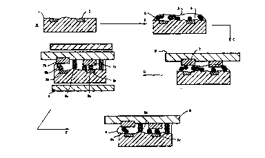
Figure 1 is a diagram showing one example of the bonding
method in the first aspect of the invention through stages A to E.
Dimensions are exaggerated in the diagram for clarity. The
electrically-conductive particles are spherical and have a
substantially uniform diameter.
(A) A circuit board 1 has metallised tracks or pads 2 thereon.
(B) A layer of composition 3 is applied thereto, the composition
comprising curable ferrofluid adhesive composition 4 and
conductive particles 5 distributed randomly therein.
WO 95/20820 PCT/IE95/00009
22 -
(C) An electronic component 6 having conductor pins 7 thereon is
laid against the composition 3. Pressure may be applied to
urge the component 6 towards the circuit board 1. The
conductor pins 7 as shown are at different levels relative to
one another and to the surface of the component 3.
(D) A magnetic field is then applied to the assembly perpendicular
to the circuit board 1 and component 6, by magnet means 8. As
a result of interaction between the ferrofluid and the
conductive particles 5, the latter lose their random
disposition and move to form a regular pattern of of aligned
particles 9, as individual particles in a monolayer 9a or in
columns 9b and 9c, the individual particles and columns being
generally regularly spaced in both X- and Y- directions so
that they form an array in a plane perpendicular to the
magnetic field. Irregularities in separation between the
tracks 2 and pins 7 are filled by aligned particles in contact
with one another, forming a column 9b. Particles in the
monolayer 9a or at each end of columns 9b are in contact with
tracks 2a, 2b and pins 7a, 7b respectively. Other columns 9c,
which do not make contact at both ends, do not provide
conductive pathways between the tracks 2 and pins 7. There is
no pathway for conduction in the X- or Y- direction.
If the circuit board 1 and electronic component 6 both had
level surfaces and were brought to a separation substantially
equal to the diameter of a conductive particle 5, all of the
pathways could be provided by single-bridging particles 9a as
individual particles in a monolayer or in chains parallel to
the tracks 2, each chain consisting of particles contacting
one another in the X direction.
(E) After curing of the adhesive composition the magnetic field is
removed leaving the array of particles 9a, 9b to form the
conductive pathways.
Figure 2 is a similar diagram showing the bonding method in
the second aspect of the invention. Reference numerals in Figure 2
WO 9S/20820 PCT/IE95/00009
2~5~
- 23 -
correspond to those in Figure 1 except that the matrix 4a is a
ferrofluid which does not incorporate adhesive and particles 5 have
a latent-adhesive property. At stage E, the latent adhesive
property of the particles 5 is activated (e.g. by heating solder
particles to melting point) either before or after the magnetic
field is removed. The ferrofluid 4a may also be removed. The
individual particles 9a and columns 9b, 9c of particles bond the
assembly together while the particles 9a and columns 9b form the
conductive pathways.
Stage F illustrates that after removal of the ferrofluid 4a, a
conventional adhesive, sealant or potting composition 10 may
optionally be added into and/or over the bond between the
components in order to enhance the bond and/or to protect the
electrical connection from adverse environmental factors.
EXAMPLE 1 Ferrofluid with non-maqnetic particles
The ordering of non-magnetic particles in a ferrofluid was
first examined in accordance with the following experiment. A
kerosene-based ferrofluid known as APG 511A was purchased from
Advanced Products and Technologies Ltd., (Oxford, U.K.) which is a
subsidiary of Ferrofluidics Corp., Nashua, NH, USA. The
characteristics of the fluid are indicated in Table 1.
Tablel
Ch7-.~ct~ icsoffe~ofluid APG 511A
Saturation Magnetisation (Gauss) 200
Magnetic field required to achieve
90% of saturation magnetisation (Oe) 2500
Initial magnetic permeability (30 Oe) 1.9
Magnetic permeability at 8000 Oe 1.02
the above values measured at 25C
Viscosity at 27C (mPa s) 40
Pour point (C) -70
Density at 25C (gm/ml) 1.12
Thermal Conductivity at 38C (mW/m K) 146
WO 95/20820 PCT/IE95/00009
24 -
Evaporation rate at 175C
(X10~7gm/cm2-sec) 7.6
To this fluid was added a qualitative concentration of
monodisperse polymer beads (<0.5% w/w). The polymer beads were
composed of polystyrene crosslinked to an extent of 55% with divinyl
benzene (PS-DVB 55%). The béads coded Q496 were purchased from Dyno
Particles AS, Lillestrom, Norway and had a mean diameter of 9.8
micrometres as measured with a Coulter (Trade Mark) LS Particles
Size Analysis apparatus operating in the Fraunhofer optical mode.
A few drops of the dispersion of Q496 in APG 511A were placed
on a microscope slide and subsequently covered with a coverslip.
The continuous liquid film thus produced was examined in
transmission in an optical microscope and the beads were seen to be
randomly or isotropically distributed in the sample as shown in
Figure 3a.
A small laboratory permanent magnet was placed parallel to the
sample and the non magnetic beads were seen to align parallel to the
field lines of the permanent magnet thereby displaying anisotropic
ordering in the so-called X-Y plane as shown in Figure 3b (i.e. the
reference plane of the sample itself). The field induced ordering
was lost shortly after the magnetic field was removed from the
sample. When the same magnet was placed directly beneath the plane
of the sample, the Q496 beads aligned vertically with respect to the
reference sample plane. From above, the sample appeared to have a
regular lattice array of beads and it was possible to conceal one
bead with another by placing the former directly beneath the latter
for example. This arrangement describes so-called Z-axis
anisotropy, i.e. wherein the structure formed by the included
particles resides at right angles to the substrate. When the same
magnet was oriented at intermediate angles between 0 and 90 degrees
to the horizontal sample, and was brought into close proximity with
the sample, the Q496 beads oriented at a tilted angle to the
horizontal plane - the tilt angle of the bead chains being governed
by the relative position of the applied magnetic field. A tilted
structure of beads demonstrating components of ordering in both the
WO 95/20820 PCT/IE95/00009
- 25 _ 21 S 8 ~ 4 1
X-Y plane and the Z-plane is depicted in Figure 3c. The
transparent beads clearly overlap in this Figure and the uppermost
bead resides in a different focal plane from the lowermost. As
before all of these anisotropic structures were lost when the
stimulating magnetic field was removed from the sample.
EXAMPLE 2 Ferrofluid with non-maqnetic particles
In order to demonstrate that anisotropic structures could be
locked in, albeit on a temporary basis, the following experiment was
conducted. A sample was prepared in accordance with Example 1
except the distance between the coverslip and the microscope slide
was set such that it corresponded to a dimension less than the
diameter of two Q496 beads, i.e. <20 micrometres. In this
arrangement it was not possible to align one bead directly on top of
another as expected. Instead a tilted arrangement of spheres
resulted such that two spheres became jammed between the substrate
and the coverslip. When the magnetic field was removed this
anisotropic tilted arrangement persisted indefinitely. The
log-jammed structure indicates intimate bead-to-bead and
substrate-to-bead contact, thus a connection between the upper
substrate (coverslip) and the lower substrate has been realised by
way of the included polymer beads. No such connection previously
existed because the sample thickness was chosen to be greater than
the diameter of an individual bead.
In spite of the fact that the abovementioned structure was
retained after removal of the magnetic field, it could nonetheless
be broken down by restimulating the sample with a magnetic field,
for example applied from a different direction. As such the
generated structures were only semipermanent.
EXAMPLE 3 Ferrofluid with non-maqnetic fibre particles
A composition such as described in Example 1 was made up except
that chopped optical fiber was used in place of the Q496 beads. The
fibers were nominally of 7.5 micrometre diameter and nominally 100
micrometres in length. The fibers were obtained from Sumita Optical
WO 95/20820 PCT/IE95/OnO09
~5~9- - 26 -
Glass Inc., Tokyo, Japan and are of the type used in the control of
cell thickness in liquid crystal display manufacture. Alignment of
these rod-shaped non-magnetic inclusions by the means described in
Examples 1 and 2 produced chains with increased contact areas
between each chain element (individual fibers) as compared to the
spherical beads of Examples 1 and 2.
Because there was a distribution of fiber lengths in the pure
fiber sample there was a corresponding distribution of lengths in
the fluid composition that contained said fibers. When such a
sample was stimulated with a magnetic field normal to the substrate
some fibers jammed between the upper and lower substrates whilst
some of the shorter lengths could be made 'tumble' by moving a
magnet across the sample.
EXAMPLES 4-6 Ferrofluid with inclusion of non-maqnetic
conductive particles
In the foregoing, alignment in various planes relative to the
horizontal substrate plane was demonstrated with a variety of
non-magnetic inclusions. Long range chain-like ordering extending
over hundreds of micrometres was apparent as was the ability to jam
structures in a direction inclined or vertical to the substrate
plane.
However the inclusions described thus far have no additional
funtionality. In the present Example alignment of a variety of
non-magnetic inclusions in APG 51lA is described. These included
particles differing from the those of Examples 1-3 in that they
possess additional functionality by virtue of the fact that they are
either inherently electrically conductive or else are electrically
insulating particles coated with a highly conductive topcoat. Thus
continuous chains of anisotropic structures could be formed as in
Example 1 but this time (Example 4) with beads (solder particles) of
an electroconductive metal alloy (63 Sn/37 Pb). The said beads are
available from Advanced Metal Technology Inc., Bradford, CT, USA and
were a 400 mesh size which corresponds to 37 micrometre diameter.
Figures 4a and 4b illustrate intimate bead-to-bead contact of
w 095/20820 2 I ~ ~ ~ A 1 PCT~E95/OOOog
- 27 -
electroconductive but non magnetic particles and long range order
(e.g. ten beads - approx. 370 micrometres) respectively.
In Example 5 a similar alignment into chains was obtained with
silver coated 'microballons' sold under the trademark Metalite
available from The PQ Corporation, Valley Forge, PA, USA. of mean
diameter 48.87 micrometres as measured with the Coulter (Trade Mark)
LS Particle Size Analysis apparatus (Fraunhofer optical mode).
These, being hollow glass beads coated with pure silver metal, have
the advantage over pure metal particles in that they have much lower
density and hence are less prone to settlement in a liquid
formulation.
In Example 6, the included material was an electroconductive
grade (known as E/HM-S) of chopped carbon fiber with a nominal 7
micrometre diameter and a nominal 250 micrometres length. This
material was purchased from Grafil Inc., Coventry, UK and is the
type used in conventional electromagnetic shielding applications and
in so called through-cell electrical connections in the liquid
crystal display industry. As before the fibers could be aligned at
will with a magnetic field in the magnetic fluid matrix.
EXAMPLES 7-15 Ferrofluid with inclusion of non-maqnetic or
maqnetic conductive Particles
A variety of further electroconductive components was included
in APG 511A as described in Examples 4-6. These formed continuous
chains of intimately contacting particles as before. The particles
in these Examples differ however from those in Examples 4-6 in that
they all contain a proportion of nickel metal. Polymer beads known
as Q504 of regular 10 micrometre diameter available from Dyno
Particles AS, Lillestrom, Norway, bearing a continuous
electroconductive nickel coating (thickness 50 nanometres), were
aligned in a magnetic field when dispersed in APG 511A as described
in previous Examples. The same particles, but coated with an
additional layer of electroconductive gold (thickness 50 nanometres)
were similarly aligned in continuous chains with intimate
bead-to-bead contact [Examples 7 - 8.] As with Example 5, the
WO 9~5/20820 PCT/IE95/00009
- 28 -
specialised Q504 particles offer the advantage of low density over
solid metal alternatives. Similarly the range of electroconductive
particles listed below which comprise nickel in bulk or coated form,
were aligned in continuous chains with contact between conducting
particles when included in the ferrofluid APF 511A and stimulated
with a magnetic field:
F~MrLE 9 Conductive Nickel Grade HCA-1
EXAMPLE10 Conductive Nickel Spheres (37 micrometres)
EXAMPLE11 Conductive Nickel Spheres (60 micrometres~
Fxr~LE 12 Nickel Powder Type 4SP (37 micrometres)
EXAMPLE13 75% Nickel - Coated Graphite
F~r~r~LE 14 15% Silver - Coated Nickel Spheres
EXAMPLE1s 15% Silver - Coated Nickel Flake
The above mentioned materials (Examples 9 - 15) are available
under the Trade Mark NOVAMET from Novamet Speciality Products Corp.,
NJ, USA and are more conventionally used as electroconductive
fillers in resin systems employed in electromagnetic shielding
applications.
EXAMPLE 16 Curable ferrofluid adhesive composition with
inclusion of non-maqnetic particles
Previous Examples have highlighted direct contact between
electroconductive particles as well as the relatively long range
order in aligned chains. This chain order extends over and above
the modest requirements of one or a few particle diameters necessary
to span typical thickness gaps between two substrates which are to
be bonded.
In the present Example APG 511A has been formulated with a
photocurable adhesive composition so that the utility of the
magnetic fluid component of the formulation can be exploited to form
useful anisotropic structures, for example with functional
particles, between substrates in the ways described in previous
Examples, and these structures can subsequently be locked in whilst
simultaneously bonding the said substrates together.
WO 95/20820 ~ ~. Ci ~ PCT/IE95/00009
- 29 -
By way of example only, a formulation comprising 95%
weight/weight triethylene glycol dimethacrylate, 5% weight/weight
acrylic acid together with 0.5 - 1.0% weight/weight of the radical
photoinitiator 2,2-dimethoxy-2-phenyl acetophenone was admixed in
approximately equal volume proportions with ferrofluid APG 511A. To
this photosensitive curable ferrofluid mixture was added a
qualitative concentration of the Q496 beads described in Example 1.
The liquid was aligned in a magnetic field as before (cf Example 1),
and whilst it was not as responsive as the pure magnetic fluid
because of the dilution with non-ferrofluid monomers, anisotropic
ordering of the included non-magnetic particles was evident. The
composition was then exposed to UV radiation (primarily 366nm) for a
few seconds which caused the sample to photopolymerise and cure.
Following this exposure the coverslip and the microscope slide were
found to be bonded together and could no longer move relative to
each other when shear forces were applied. Furthermore the
anisotropic structures generated before the irradiation process were
permanently locked in after the irradiation process. The structures
generated in the fluid state and subsequently locked into the solid
state could neither relax nor be perturbed by external magnetic
fields irrespective of their field strength. An indication of
ordering could also be perceived macroscopically with this sample.
Thus for example when the curable ferrofluid mixture containing Q496
inclusions was placed on top of a cylindrical permanent bar magnet,
then photocured, a circular image of the magnet's end piece could be
seen by unaided visual inspection. This image was permanently set
in the sample. This can be explained by consideration of the field
induced vertical ordering of the coloured composition relative to
the substrate plane which gives rise to a dichroic effect between
the aligned area over the pole piece and the unaligned areas distant
from the pole piece.
EXAMPLE 17 Curable ferrofluid adhesive composition with
inclusion of non-maqnetic particles
A curable formulation was prepared based on a so-called 'air
activated' free-radically polymerisable acrylic monomer composition
as described in Example 20 of Loctite Patent Application EP 0 502
WO 95/20820 PCT/IE95100009
~ 5 ~ 30 -
733A , the contents of which are incorporated herein by reference.
The composition comprises hydroxypropyl methacrylate (8.5g),
methacrylate acid (0.59), N-phenyl-2-propyl-3,5-diethyl
-1,2-dihydropyridine (0.59) and 0.1% iron (III) acetylacetonate in
hydroxypropyl methacrylate. The formulation based on this monomer
composition, ferrofluid APG 511A and particles Q496 was prepared by
admixing the monomer composition with the particle loaded ferrofluid
in approximately equal volumes. The mixing was performed in an
ambient air atmosphere which is known to activate the curing
mechanism in the adhesive component of the formulation. The thus
formulated mixture was placed on a substrate which rested on the end
of a circular permanent magnet and the liquid was subsequently
covered by a coverslip. The mixing time dictated the period during
which the layer remained exposed to the air before being closed off
from the atmosphere by the coverslip and essentially allowing an
anaerobic cure to ensue. As in Example 16, anisotropic structures
generated and sustained in the liquid state were permanently set in
the cured solid state and could not subsequently relax or be
perturbed by an external magnetic field irrespective of their
strength. Again a macroscopic dichroic effect could be discerned by
unaided visual inspection and again the coverslip and microscope
slide were permanently bonded together. It was noted that
structural anisotropic ordering of the particles was not retained in
a thin boundary zone around the perimeter of the otherwise cured
sample. This phenonemon was attributed to lack of cure in this
boundary sample/air interfacial region due to a measure of air
inhibition and diffusion into the sample from the edges. This
effect further emphasises the importance of cure for the permanent
locking of aligned anisotropic structures in the samples.
EXAMPLES 18-19 Curable ferrofluid adhesive composition with
inclusion of non-maqnetic electrically-conductive
particles
The present Example describes a composition similar to Example
16 but with inclusion of electroconductive particles in place of
Q496 particles. The particles known as Q504 and previously
described (in Examples 7 and 8) are crosslinked polystyrene beads of
WO 95/20820 PCT/IE95/00009
- 31 ~ S~
a nominal 10 micrometre diameter and bear a nickel coat or a gold
coat deposited on top of a nickel subcoat. Both variants are
electroconductive. It is important to note that even though
elemental nickel is ferromagnetic, neither the pure coated nickel
version nor the gold on nickel-coated version of Q504 could align in
response to strong magnetic fields when suspended in non-magnetic
liquids, e.g. monomers such as acrylic acid, in contrast to the
extensive alignment noted when the same particles were suspended in
a ferrofluid (cf. Examples 7-8).
A formulation employing acrylic acid with approximately 1%
radical photoinitiator 2,2-dimethoxy-2-phenyl acetophenone and
approximately 50% by weight of ferrofluid APG511A was prepared. To
this formulation was added a qualitative concentration of Q504 in
either the pure nickel-coated or gold on nickel-coated forms
[Example 18]. The formulation showed no signs of incompatibility in
the liquid form and was quite responsive to magnetic fields.
Application of magnetic fields parallel to the substrate caused
alignment of the nonmagnetic electroconductive particles. Figure 5
shows the scale of alignment capable in this polymerisable system
using nickel-coated polystyrene particles. The figure shows
alignment over some forty particle diameters (>400 micrometres) with
intimate contact between the electroconductive beads. A
photopolymerised version of this system is shown in Figure 6. The
formulation required 8 seconds to cure (1W/cm2, 365nm). After
polymerisation the interparticle tracks showed striations indicating
phase separation of the now polymerised monomer (acrylic acid) from
the ferrofluid. Figure 7 depicts a "before and after" photocure
situation for a similar formulation containing gold on nickel which
indicates retention of alignment after photocure and highlights the
slight shifting of the particles which accompanies shrinkage during
cure in thi 5 S i mple monomer mixture.
Example 19 differs only from Example 18 in that Q504 was
replaced with the Silver particles sold under the Trade Mark
METALITE as described previously in Example 5. These represent
examples of particles which have low density, are electroconductive
and are nonmagnetic. Particle size analysis indicates a mean
WO 9S/20820 PCT/IE95/00009
~ ,S~ t~ _ 32-
diameter of 49 micrometres for the said particles. Figure 8
indicates aligned tracks of METALITE beads, again extending over
some 400 micrometres (same magnification as Figure 5) after
photopolymerisation. Striations can again be discerned proving
polymerisation has occurred.
As with Examples 16 and 17, once polymerisation had been
induced in the foregoing Examples (18 and 19), the aligned particles
could no longer be perturbed with external magnetic fields and the
alignment was permanently set in.
The nickel-coated particles such as Q504 appeared to be much
more readily aligned than particles which were not coated with a
ferromagnetic material, for example Q496, tested when in a
ferrofluid environment (note that they do not align in any other
liquid). There thus appears to be a synergism between these
particles and the ferrofluids or their mixtures with monomers which
can be used to advantage. Nevertheless the nickel-coated particles
are regarded as "non-magnetic" within the definition above.
EXAMPLE 20 Anisotropically-conductive ferrofluid adhesive
composition
Commercially available ferrofluid (APG 511A) was formulated
with acrylic acid in a 1 : 1 mixing ratio. The mixture was checked
under a microscope to ensure that a uniform magnetic fluid was
intact. The mixture was both uniform and responsive to magnetic
field gradients. To the mixture was added 6% w/w (weight/weight) of
radical photoinitiator, 2, 2-dimethoxy-2-phenyl acetophenone and 20%
w/w of spherical gold-coated polymer beads of 12 micrometre diameter
available from Sekisui Fine Chemical Co., Osaka, Japan. One sample
of the mixture was spread on a glass plate, covered with a
transparent slip and aligned in a uniform magnetic field of 300 Oe
applied normally to the sample. Gentle pressure was applied to the
top plate after ordering of the beads. The sample was photo cured
on exposure to UV light from below (20 seconds, 100mW/cm2). Order
was seen to be preserved after cure.
WO 95/20820 PCT/IE95/00009
_ 33 2 ~ 5 ~
To a second sample of the above mixture was added 2% w/w of
radical thermal initiator AIBN (2, 2'-azobis isobutyronitrile).
This sample could be thermally cured in an oven at 110C for 30
minutes. The liquid sample was applied to a test circuit comprising
a patternwise delineated array of parallel copper tracks of 100
micrometre width and separated by a maximum of 150 micrometres and a
minimum of 35 micrometres. This sample was aligned in a uniform
magnetic field of 300 Oe strength applied in a normal direction.
Conductor beads adopted an ordered disposition with no two beads
touching when the sample was further confined with a top plate.
Transparent electrically insulating top plates were used to check
ordering and electrical continuity in the XY plane whereas copper
top plates were used to test electrical continuity in the Z-axis,
5 i.e. in the direction normal to the bondline. The ordered sample
was clamped in a specially designed rig and placed in an oven to
induce thermal cure. Order was preserved after clamping and curing
verified by independent checks. Z-axis contact resistance, measured
by the four point probe method with a Gen Rad 1689 Precision RLC
Digibridge, for the cured sample averaged 0.9 ohm whereas XY contact
resistance measured between nearest neighbour conductive tracks on
the test circuit was in the megaohm range.
EXAMPLE 21 Anisotropically-conductive adhesive comPosition in
which monomer forms the ferrofluid matrix
Examples 16 and 17 describe the locking in of ordered
structures of non-magnetic beads which were previously aligned in
admixtures of standard polymerisable monomers and commercially
available ferrofluids using uniform magnetic fields.
The present example describes the preparation and testing of
polymerisable monomers which are inherently ferromagnetic liquids
and which also contain non-magnetic conductive microparticles.
Magnetite particles of average particle diameter 9.7
nanometres, (Liquids Research Limited, Unit 3, Mentech, Deiniol
Road, Bangor, Gwynedd, U.K.) were coated with oleic acid and
dispersed in heptane at an appropriate content (3.5% and 8.4%) by
WO 95/20820 PCT/IE95/00009
S~ 34 -
volume magnetite to produce fluids with magnetisation saturation of
100G and 250G as described below. Five mililitres of the above
mentioned heptane-based material was added to 5ml of
triethyleneoxide dimethacrylate (triegma) and a further 2ml of a
secondary surfactant was added which was an acid form of an aromatic
phosphate ester sold under the Trade Mark GAFAC RE610 by GAF (Great
Britain) Limited and now available as RHODAFAC RE610 = GAFAC RE610
from Rhone Poulenc Chimie, France. This is described as
nonoxynol-9-phosphate.
Removal of the heptane left a good uniform ferrofluid on
visual inspection which responded to a magnetic field gradient.
After standing for 72 hours in a glass bottle, however, the
unstabilized colloid polymerised to a brittle solid.
In a second experiment the polymerisable material was now
butane diol dimethacrylate which is less sensitive to atmospheric
oxidation than triegma. Using the same proportions as above, a good
quality ferrofluid resulted with good stability. Fluids with
magnetisation saturation of 100 G and 250 G were thus prepared. The
saturation magnetisation curve was steep and typical of
superparamagnetic systems in that it exhibited no hysteresis. These
fluids, even when formulated with radical initiators, were stable
for periods of one year at room temperature when stored in air
permeable polyethylene bottles such as those used for the storage of
traditional anaerobic adhesives by those skilled in the art.
The butane diol dimethacrylate ferrofluids could be
polymerised in the bulk with standard radical photo and thermal
initiator systems. It is likely that the triegma system polymerised
through a redox-initiated polymerisation given the easily oxidised
nature of the dimer backbone and the fact that iron is present in
the system. It is believed that appropriate selection of
stabilizers would avoid this problem.
To the butane diol dimethacrylate based ferrofluid of 100G was
added approximately 5% weight/weight spherical gold-plated
cross-linked polystyrene microparticles of 7 micrometre diameter.
WO 95/20820 PCT/IE95/00009
_ 35 ~158~
The said particles are essentially monodisperse (i.e. of
substantially uniform shape and diameter) and are an article of
commerce from Sekisui Fine Chemical Co Ltd, Osaka, Japan.
The particle loaded polymerisable ferrofluids were aligned in
a permanent magnet capable of generating a uniform magnetic field
which was continuously variable up to 300 Oe. The said magnetic
field could be applied in directions either parallel or
perpendicular to the ferrofluid adhesive sample. The permanent
magnet was designed to be mountable on an optical microscope so that
the aligning process could be monitored in real time. To the
underside of the magnetic microscope stage was fitted a parabolic
mirror with an optical waveguide fitted in its centre. The
waveguide was linked to a remote UV source (EFOS Ultracure 100 SS,
available from Jenton International, Andover, Hants. UK).
The conductive microparticles were aligned in the ferrofluid
adhesive matrix (formulated with the photoinitiator from Example 20
at 6% w/w) confined between two optically transparent substrates.
Alignment was judged to be sufficient after some 60 seconds with the
field perpendicular to the sample plane. The samples were examined
in reflection with the parabolic mirror acting as reflector and
means for concentrating light onto the sample for the purposes of
photocure. The sample was irradiated from below (20-60 second
bursts). The matrix polymerised and took on a fine grain structure
not present in the liquid state. The two substrates were bonded
together and the regular conductor array could no longer be
disturbed when stimulated with a magnetic field.
The quality of the particle ordering was high and was assessed
with the aid of an Optical Image Analyser (Buehler Omnimet 3 Image
Analyser, Illinois, USA). Optical field images of ordered conductor
particles (7 micrometres) in polymerised ferrofluid acrylic matrices
are shown in Figure 9. Figure 9a at 40X magnification shows the
macroscopic nature of the effect while Figure 9b at ZOOX
magnification shows the ordering of the particles in a detail of the
sample. It can be seen that no aggregation of particles is
evident. The high quality ordering was achieved on a macroscopic
WO 9S/20820 PCT/IE95/00009
5~
scale on a sample of some 600 mm2 with the current system.
Ordering quality was assessed over 60 representative optical
fields taken at random from the same sample. The conditions and
data for the test were as follows:
Magnetic field : Uniform 300 Oe applied perpendicular to the
sample plane.
. Conductors : gold-coated cross-linked polystyrene 7 micrometre
beads at approximately 5% wt/wt.
Matrix : ferromagnetic dimethacrylate 100G with photoinitiator
as per Example 16.
. lX Optical field area : 105 micrometres2
. Total Area Examined : 6 X 10⁶ micrometres2
Field Count : 60
Magnification/Geometry : X 200 in Transmission (for Image
Analysis)
. Area covered by particles per field : mean = 5173.3
micrometres2, std.dev = 605 micrometres2.
Area % covered by particles per field : mean =5.136%; std.
dev. = 0.601%.
Particle count per field : mean = 159; std. dev. = 18.
. Sample Area occupied by single particles: 5.071%.
. Sample Area occupied by two particles touching: 0.057%.
Of the 9566 particle objects detected in the 60 fields, only
46 appeared as two particle aggregates (mean length = 13.8
micrometres; std. dev. - 0.72 micrometres; some may be slightly
tilted). Only one single object in the 9566 objects (which
corresponds to 104 ppm) appeared as an aggregate 18.3 micrometres in
length. These data suggest that this system is capable of resolving
electrical contacts separated by approximately 18 micrometres with a
high degree of confidence.5
Samples were electrically tested on test circuits with a
minimum of 35 micrometres track separation. The test circuit
comprised 60 interdigitated metal tracks each 100 micrometres wide
deposited on a float glass substrate. The metalisation pattern
WO 95/20820 PCT/IE95/00009
~ 1 r~ (~3 9 ~7 ~,
~ 37 ~
comprised a thin layer of copper sputtered onto a titanium tungsten
seed layer. A 1 9 sample of the ferrofluid acrylic adhesive
containing 0.159 of 5 micrometre gold-coated polystyrene beads and
0.01 9 of the radical photoinitiator cited in Example 16 together
with 0.02 9 of radical thermal initiator AIBN was smeared onto the
electrode array and an IT0 (indium tin oxide) coated glass top
electrode (60 X 12 X 1 or 2mm) was placed on the liquid sample. The
sample was stimulated with a uniform magnetic field and the ordering
was checked with a microscope. Pressure was applied to the sample
in a controlled fashion in a press fitted with a pressure
transducer. Pressures of up to 3 MPa were applied to samples to
achieve bondline thicknesses not more than the diameter of the
conductive particle. The sample was thermally cured under
pressure. The contact resistance was 1 ohm in the Z direction, i.e.
through the bondline. When the measurement was made with a copper
top plate in place of the IT0 plate, the Z axis contact resistance
was in the order of 0.5 ohm. When an insulating glass plate was
used as top electrode and contact resistance was measured in the
bondline XY plane between nearest neighbour tracks, values of 5
megaohms were typical. Electrical measurements were made using the
four point probe method with Gen Rad 1689 Precision RLC Digibridge.
EXAMPLE 22 EpoxY resin adhesive composition in which the
monomer forms the ferrofluid matrix
Example 21 described the preparation, characterisation and
testing of acrylic based adhesives. The present example describes
the preparation of epoxy-based ferromagnetic adhesives.
A ferromagmetic epoxy resin adhesive was prepared as follows:
1. Surfactant coated magnetite particles, similar in size to
those cited in the above mentioned example, were dispersed in
heptane to produce a regular ferrofluid.
2. The particles were next flocculated in acetone, mixed with a
standard bisphenol A diglycidyl ether epoxy resin (10 mls of
ferrofluid to 10 9 of epoxy) and 0.8 9 of the secondary surfactant
WO 95/20820 PCT/IE95/00009
2 ~ ~ ~J 3 ~ 38
GAFAC RE610 (cf. Example 21) was added which was compatible with
the resin.
5 3. Temperature was raised to 115C to ensure thorough mixing
and the solvent was subsequently removed. Care was taken not to
heat much beyond 1 30C to avoid thermal polymerisation.
The above procedure produced a 240 G ferromagnetic epoxy
composition which was subsequently formulated with either a
photocationic initiator such as GE1014 (General Electric) at 1-2%
v/v or a latent amine hardener such as that described in Example 1
of GB 1121196 which is an article of commerce from Ciba-Geigy sold
as product HT9506. The latter was formulated at close to
stiochiometric equivalents. The alternative formulations thus
produced either photosensitive epoxies curable with UV irradiation,
or thermally sensitive epoxies curable by heating up to 150C for
up to 30 minutes. The original bulk viscosity of the epoxy filled
with magnetite was 1.4 X 10⁶ mPa s at 250C measured with a
shear rate of 10~1 on a Haake rheometer (Karlsruhe, Germany). In
order to achieve particle ordering in these ferrofluid epoxies when
microparticles were subsequently admixed, it was necessary to dilute
the formulations with reactive epoxy diluents (1:1 and 1:2, epoxy :
diluent for photo and thermal curing adhesives respectively) such as
the short chain diepoxies available from Dow Chemical Company (eg.
DER 736 Epoxy resin). Light sensitive samples were photocured for
60 seconds with a lOOW UVALOC lamp whereas thermally sensitive
samples cured at 100C after 15 minutes heating. Particle loaded
samples were subjected to similar conditions for aligning,
characterising and testing as those described in the previous
example and similar results were achieved, the contact resistance
being Ohms in Z axis and MOhms in XY axis for samples with a nominal
loading of 5% w/w of gold-coated particles having an average
diameter of 12 micrometres.
EXAMPLE 23 Anisotropically-conductive ferrofluid solder
composition
A commercially available solder powder (in the form of uniform
WO 95/20820 PCT/IE9S/00009
2 1
beads of a diameter of about 40 micrometres) [Advanced Metal
Technology Inc., Bradford, CT, USA] is added to the commercially
available ferrofluid APG 511A (Advanced Products and Technologies
Ltd., Oxford UK which is a subsidiary of Ferrofluidics Corp.
Nashaua, NH, USA). Each component is present to the extent of 50
weight percent. The viscosity of the ferrofluid is 40 mPa s at
27C. The solder particles behave as magnetic holes in the
ferrofluid and can be aligned by a magnetic field as disclosed in
Example 4. After the composition has been applied to a substrate
the solder particles are fused together by heat and this action
causes adhesion of the conductive solder to the substrate. The
experiment is repeated so that the ferrofluid-solder mixture is
confined between two substrates which are conductive and which can
normally be easily wetted by solders e.g. tinned substrates or
cleaned copper substrates which may or may not have pattern
delineation. The solder particles are aligned as before in the
ferrofluid and are fused together by heat and this action serves to
electrically connect the upper and lower substrates together. For
patternwise delineated substrates the resolution technique i-s
determined by the solder bead diameter (in this case approximately
40 micrometres), the solder particle concentration and the strength
of the aligning field.
The ferrofluid, which has served its function of aligning the
solder particles, is now redundant but may be left in place,
encapsulated subsequently with a conventional adhesive, sealant or
potting composition, or recovered with a magnet from the assembly,
after which the ferrofluid may be recycled for subsequent use and
the vacated space may if desired be filled with a conventional
curable insulating material. This added material may have adhesive
properties to reinforce the conductive bridge and will help to hold
the particles in place while also preventing any electrical jumping
from one bridge to another or entry of contaminants which may short
out or cross one conductive bridge with another.
WO 95/20820 PCT/IE95/00009
~ ~5 ~ 40 -
EXAMPLE 24 Ferrofluid compositions containinq particles with
heat-activated adhesive layer
Adhesive coated polymer beads of uniform 7.25 micrometre
diameter available from Sekisui Fine Chemical Co, Osaka, Japan (Type
CB) were added to the commercially available ferrofluid APG 511A
(Advanced Product and Technologies Ltd, Oxford, UK) as before , ie,
50% w/w. The particles behave as magnetic holes in the ferrofluid
matrix and therefore may be ordered in structural arrays by means of
a uniform magnetic field. The ferrofluid mixture comprising said
beads was confined between two glass substrates and the assembly was
subjected to a magnetic field which ordered the beads. The
substrates were clamped together and heated to 140C for 30
minutes which activated the adhesive coating on the beads. Due to
the relatively small contact area the bond made by the coated beads
was not strong. The bond can be supplemented by removing the
ferrofluid matrix from between the substrates and replacing it with
conventional adhesive.
Gold-coated 7 micrometre polymer beads are available from the
same supplier as the aforementioned particles but adhesive-coated,
gold-coated particles were not immediately available. The latter
particles are viewed as being useful with regard to bonding and
electrical conduction especially when the space between the
substrates is filled with adhesive as previously described.
EXAMPLE 25 Anisotropically-conductive composition in which
solder flux forms the ferrofluid matrix
A ferromagnetic solder flux was prepared from a solid rosin
which has abietic acid as its chief constituent. The flux was
prepared by the redistribution of special grade magnetite particles
of 9.7 nanometers average particle diameter into solutions of rosin
followed by removal of the solvent. A high quality ferrofluid
resulted which solidified on cooling from the melt. The ferrofluid
solder flux was used as a matrix for solder particles (63Sn/37Pb)
which were nominally 20 - 25 micrometre diameter. The solder
particle loading was approximately 20% w/w. The ferrofluid
WO 95/20820 PCTIIE95/00009
2 ~ t~
- 41 -
rosin-solder particle mixture was tested on a custom designed test
circuit. The circuit consisted of 60 interdigitated copper
electrodes grouped in sets of ten tracks. Each track was 100
micrometres wide and the inter track separation decreased in steps
of 25 micrometres from an initial 150 micrometres. The metalisation
pattern was deposited on a float glass substrate. The ferromagnetic
rosin with solder particles was melted at about 135C which was an
insufficiently high temperature to melt the solder itself. The
molten sample was covered with a transparent, insulating top plate
and inserted into a specially designed permanent magnet which
provided a uniform field of 300 Oe over areas of 1 cm2 or slightly
greater. The sample was stimulated in this case with a field set
normal to the plane of the test sample. The magnetic system was
designed for mounting onto a laboratory microscope and the ordering
of the solder particles in the molten ferromagnetic flux could be
observed. The ordered solder particles retained their positions
relative to one another (none touching) when the sample cooled in
the magnetic field. The system could be reworked by remelting.
A similar sample was prepared on the test circuit except that
in this case, a copper conductive top plate (60 X 12 X 1 or 2mm) was
used in place of the insulating glass plate. Ordering was checked by
microscopic inspection from the underside of the sample which
indicated particle separation and ordering of the beads in the
intertrack spaces. Contact resistance measurements made normal to
the bondline formed by the flux/solder paste indicated were
approximately 1 Ohm in magnitude and no inter track connectivity
could be observed above 25 micrometres separation.
When samples similar to those described in the preceding
paragraphs were clamped and heated to greater than the melting point
of the solder particles (approximately 180C) and re-examined
optically and electrically, the following results were obtained:
Electrical contact resistance in the Z-axis, i.e. normal to
the bondline averaged 0.2 ohm and no bridging of neighbouring tracks
in the XY plane was observed above the 25 micrometre track
separation.
WO 95/20820 PCT/IE95/00009
~ r ~ 42
Even in the case of the 25 micrometre track separation, the
vast majority of these tracks were not bridged. Figure 10 shows
solder plating of 100 micrometre tracks after melting of ordered
particles; melted particles in intertrack spaces are also seen,
these do not contribute to contact resistance. The sample is viewed
in reflection (X40 magnification in Figure 10a and X200
magnification in Figure 1Ob) from above through a clear glass
plate. The bright areas are the tracks coated with solder. The
inter-track areas are mainly grey with black zones of
magnetite-filled rosin and light circles of solder.
This example may be varied by carrying out the heating step to
melt the solder while the magnetic field is applied.
EXAMPLE 26 PreParation of a Ferrofluid/Gold Co-colloid
A gold sol was prepared as follows: 1 cm3 of a 1% solution
of Hydrogen Tetrachloro Aurate (HAuCL43H20) available from the
Aldrich Chemical Co. UK, Gillingham, Dorset was added to 100 cm3
of distilled water. At this point 2.5 cm3 of a 1% sodium citrate
solution was added and the mixture was kept just at the boil. After
a few minutes a blue colour became apparent followed shortly after
by a ruby red colour.
The ruby red gold sol, which was stable at room temperature,
was added in an approximately 1:1 volume/volume ratio to the
commercially available aqueous based ferrofluid known as EMG 708 (a
Ferrofluidics Corp., Nashau, NH, USA, product) available from
Advanced Products and Technologies Ltd., Oxford, UK. The mixed sol
and ferrofluid showed no signs of incompatibility even after several
weeks storage at room temperature. Some chopped glass fibres
nominally of 7.5 micrometre diameter (cf. Example 3) were added as
internal standards to aid visual examination under the optical
microscope.
A drop of the mixture was placed on a microscope slide and
covered with a cover slip. Examination by microscope showed a
uniform heterogeneous viewing field with an orange-brown colouration
W 095/20820 21 5 8 ~9 ~ :~ PCT~E95/00009
- 43 -
(colour dominated by the ferrofluid) and no discernible features
whatsoever except for the few deliberately added focusing aids in
the form of chopped glass fibre.
On the application of a magnetic field from a small laboratory
permanment magnet, the optical field was seen to develop features in
the form of aggregates of the non magnetic component (gold) which
formed lines parallel to the direction of the applied magnetic
field. The lines of what is effectively destabilized gold colloid
or aggregates of gold generated in situ, could be oriented at will
by movement of the stimulating magnetic field. In this Example the
gold aggregates are behaving as magnetic holes in the ferrofluid
matrix.
Figure 11a shows a photomicrograph at 50X magnification after
the application of a magnetic field to the co-colloidal system. The
object in the lower left hand corner of the photograph is a glass
fiber of approximately 7.5 micrometre diameter and is useful as an
internal size standard, thus the lines of gold aggregates are of
less than a few micrometres in width and thousands of micrometres in
length. Figure 11 b shows further detail of these fine parallel gold
lines. It should be noted also that the lines of aggregated gold
can be oriented normal to the substrate.
A gold sol may be prepared in a polymerisable matrix such as
methyl methacrylate according to the procedure of Nakao (J. Chem
Soc., Chem Commun., 826, 1993); more elaborate methods for the
preparation of gold colloids in polymerisable systems have been
described by Cardenas et al. (loc. cit.). The gold sol in monomer
is mixed with a polymerisable ferrofluid composition such as those
described in Examples 17-20. The magnetic field is applied to
effect alignment of magnetic holes comprised of aggregated gold
according to the procedure detailed above. The composition is cured
to lock the structure in place.
Although Examples 1-15 and 26 do not describe curable
compositions, and Examples 1-3, 16 and 17 do not describe the
inclusion of electrically-conductive particles, inferences may be
w 095/20820 ~ PcTnEss/oooos
2 L S ~ - 44 -
drawn from these Examples concerning the behaviour of the
respective components when combined in a composition according to
the invention. Therefore the components used in Examples 18 - 22
may be varied by substitution of equivalent components from earlier
Examples.
Industrial Applicabilitv
The invention is capable of exploitation in the electronics
industry for the assembly of components having respective sets of
conductors.