Language selection

Search

Patent 2159040 Summary

Third-party information liability

Some of the information on this Web page has been provided by external sources. The Government of Canada is not responsible for the accuracy, reliability or currency of the information supplied by external sources. Users wishing to rely upon this information should consult directly with the source of the information. Content provided by external sources is not subject to official languages, privacy and accessibility requirements.

Claims and Abstract availability

Any discrepancies in the text and image of the Claims and Abstract are due to differing posting times. Text of the Claims and Abstract are posted:

  • At the time the application is open to public inspection;
  • At the time of issue of the patent (grant).
(12) Patent: (11) CA 2159040
(54) English Title: AMMONIA ABSORPTION REFRIGERATION CYCLE FOR COMBINED CYCLE POWER PLANT
(54) French Title: CYCLE DE REFRIGERATION PAR ABSORPTION DE L'AMMONIAC POUR LES CENTRALE ELECTRIQUES A CYCLE COMBINE
Status: Expired and beyond the Period of Reversal
Bibliographic Data
(51) International Patent Classification (IPC):
  • F02C 7/12 (2006.01)
  • F01K 23/10 (2006.01)
  • F02C 7/143 (2006.01)
  • F02G 3/00 (2006.01)
  • F25B 15/04 (2006.01)
  • F25B 27/02 (2006.01)
(72) Inventors :
  • DEVAULT, DOUGLAS J. (United States of America)
(73) Owners :
  • THE BABCOCK & WILCOX COMPANY
(71) Applicants :
  • THE BABCOCK & WILCOX COMPANY (United States of America)
(74) Agent: SMART & BIGGAR LP
(74) Associate agent:
(45) Issued: 1999-11-23
(22) Filed Date: 1995-09-25
(41) Open to Public Inspection: 1996-03-28
Examination requested: 1995-12-22
Availability of licence: N/A
Dedicated to the Public: N/A
(25) Language of filing: English

Patent Cooperation Treaty (PCT): No

(30) Application Priority Data:
Application No. Country/Territory Date
08/313,699 (United States of America) 1994-09-27

Abstracts

English Abstract


A power plant utilizing combined mode steam and gas
turbines runs a refrigeration cycle powered by the energy
in the rejected heat from the steam turbines and/or other
waste heat source to cool the ambient inlet air to the
gas turbines to have them operate more efficiently.


Claims

Note: Claims are shown in the official language in which they were submitted.

CLAIMS:
1. A system for utilizing the rejected heat from a
waste heat source to operate a refrigeration cycle for
cooling ambient air for a gas turbine comprising:
a heat exchanger containing a strong solution of
ammonia and water connected to said waste heat source to
exhaust the rejected heat therein to vaporize the ammonia
from the solution to form a high pressure ammonia vapor;
means for converting the vaporized ammonia from said
heat exchanger to liquid ammonia;
means for throttling the liquid ammonia from said
converting means to lower a pressure and temperature
thereof;
evaporator means for cooling ambient air below an
outside ambient air temperature by converting the liquid
ammonia from said evaporator cooling means into a low
pressure ammonia vapor and passing the cooled ambient air
to a gas turbine compressor; and
means for supplying the low pressure ammonia vapor to
an absorber for producing the strong solution of ammonia
and water for said heat exchanger.
2. A system as set forth in claim 1 wherein said
converting means includes a water cooled condenser
connected to said waste heat source.
3. A system as set forth in claim 2 wherein said
throttling means includes an expansion valve connected
between said water cooled condenser and said evaporator
cooling means.
9

4. A system as set forth in claim 3 wherein said
evaporator cooling means contains an evaporator coil
therein for cooling ambient air prior to supplying same to
the compressor of said gas turbine.
5. A combined cycle electric power generating plant
having a steam generator, comprising:
a steam turbine driven by steam from a steam
generator and providing rejected heat to a steam
condenser;
a heat exchanger containing a strong solution of
ammonia and water connected to said steam condenser to
exhaust the rejected heat therein to vaporize the ammonia
from the solution to form a high pressure ammonia vapor;
means for converting the vaporized ammonia from said
heat exchanger to liquid ammonia;
means for throttling the liquid ammonia from said
converting means to lower a pressure and temperature
thereof;
evaporator means for cooling ambient air below an
ambient temperature by converting the liquid ammonia from
said evaporator cooling means into a low pressure ammonia
vapor;
means for supplying the low pressure ammonia vapor to
an absorber for producing the strong solution of ammonia
and water for said heat exchanger; and
a gas turbine having a compressor which receives and
utilizes the cooled ambient air to increase an amount of
net generated power in the combined cycle electric power
10

generating plant.
6. A combined cycle electric power generating plant
as set forth in claim 5, wherein said converting means
includes a water cooled condenser connected to said steam
turbine condenser.
7. A combined cycle electric power generating plant
as set forth in claim 6, wherein said throttling means
includes an expansion valve connected between said water
cooled condenser and said evaporator cooling means.
8. A combined cycle electric power generating plant
as set forth in claim 6, wherein said evaporator cooling
means contains an evaporator coil therein for cooling
ambient air prior to supplying same to the compressor of
said gas turbine.
11

Description

Note: Descriptions are shown in the official language in which they were submitted.


21~904~
-
CASE 5559
Al\1MONIA ABSORPTION REFRIGERAlION CYCLE
FOR COMBIN~D CYCLE POWER PLANT
BACKGROUND OF THE ~NVENTION
1 . Field of the Invention
The present invention relates to steam power plants
for generating electricity in general and more
particularly to such plants utilizing combined cycle
steam and gas turbines to provide more efficient and
increased capacity power generation.
2 . Desc~ption of the Related Art
~ Conventional power plants generate steam to drive
steam turbines which generate electricity. The condenser
of these steam turbines produces a significant amount of
waste heat which is rejected. This heat rejection
greatly reduces the cycle efficiency of the steam cycle.
Many power plants are adding gas turbines operating
in a combined cycle with the steam turbines to boost
plant cycle efficiency and to increase the power capacity
of the power generating plant. These turbines can also
generate waste heat fro~ such devices as a compressor
intercooler.

`-- 21~90~0
CASE 5559
Problems surface with the use of the gas turbines in
the combined cycle mode. When outside ambient
temperatures are high, these ambient temperatures affect
the capacity of the gas turbine whose output is inversely
proportional to the ambient air intake temperature.
Thus the prior art needed a power plant where gas
turbines running in a combined mode with steam turbines
could operate at a decreased inlet air temperature.
0 S~RY OF T~IE INVENT~ON
The present invention solves the problem associated
with prior art power plants utilizing combined steam and
- gas turbines as well as others by providing a power plant
where the gas turbines operate at a decreased inlet air
temperature cooled by the energy in the rejected heat
from the condenser of the steam turbine and/or other
waste heat sources.
To accomplish this the energy from the steam turbine
condenser and/or other waste heat sources along with the
favorable thermodynamic properties of ammonia are
utilized to operate a refrigeration cycle cooling the
ambient air entering the gas turbine compressor in a
combined cycle power plant.

~1 5904~
In view of the foregoing it will be seen that one
aspect of the present invention is to provide a more
efficient combined cycle power plant utilizing steam and
gas turbines.
Another aspect of the present invention is to
provide cooled gas turbine inlet air for a combined cycle
power plant. Yet another aspect of the present invention
is to utilize the rejected heat energy from the condenser
of the steam turbine and/or other waste heat sources to
operate a refrigeration cycle for cooling the gas turbine
compressor inlet air of a combined cycle power plant.
These and other aspects of the present invention
will be more fully understood upon a consideration of the
following description of the preferred embodiment when
considered in conjunction with the drawing.
BRIEF DESCRIPTION OF THE DRAWINGS
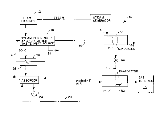
The drawing depicts a schematic of the present
invention utilizing the heat from a steam turbine
condenser to run a refrigeration cycle cooling the gas
turbine inlet air of a combined mode power plant.

-- 2159U4~
CASE 5559
DESCRIPTION OF THE PR~ RED EMBODIMENTS
With reference to the drawing, it will be understood
that the depiction is of a preferred embodiment of the
present invention but that the invention is not limited
thereto but includes all equivalents covered by the
claims. In particular the drawing illustrates the use of
a steam turbine condenser but other waste heat sources
may be used in addition to or instead of.
An electric power generating plant 10 is operated in
a combined cycle mode utilizing steam turbines combined
with gas turbines 14 to generate electricity therefrom in
a more efficient manner to produce increased plant 10
- capacity. This is accomplished by utilizing rejected
waste heat energy, such as from the steam turbines 12
captured in the steam turbine condensers 16, to power an
ammonia absorption refrigeration cycle to cool the
ambient air used by the gas turbine 14.
As is well known, high ambient air temperatures
decrease the capacity of the gas turbine air compressor
and thus reduce the output of the gas turbine 14. The
present invention thus cools the ambient air by utilizing
waste heat energy to increase the amount of net generated
power.

-
-' 21590~0
CASE 5559
The ammonia absorption refrigeration cycle begins
with an absorber 18 containing a weak ammonia-water
solution. Ammonia vapor is inputted to the absorber 18
along low pressure line 20 from an evaporator 22. The
ammonia vapor is absorbed into the weak ammonia-water
solution in absorber 18 to produce a strong ammonia-water
solution which is pumped by a pump 24 through a heat
exchanger core 26 to the waste heat source 16.
The heat exchanger core 26 is encased in a housing
28 supplied along line 30 by a weak solution of
water/ammonia remaining from cooling the rejected steam
from steam turbine 12. Stream 36 is the ammonia vapor
created from the heat rejection in condenser 16. The
heated solution in housing 28 causes the strong ammonia-
water solution in the core 26 to be heated prior toentering the condensers 16 along line 32. The heated
strong ammonia-water solution recovers heat from the
condensing steam in the condensers 16 to vaporize most of
the ammonia out of the solution to again form a weak
ammonia-water solution which is passed to the housing 28
along line 30. Condensate is drained from the condensers
16 along line 34 to be returned to the steam cycle.
The vaporized ammonia in condensers 16 is outputted
along line 36 as a high pressure ammonia vapor to a

-- 21~90~0
CASE 5559
condenser 38 where it is condensed to liquid ammonia by a
heat exchanger coil 40 located therein which is supplied
with cooling water flowing through the coil 40 from inlet
42 to outlet 44.
The liquid ammonia from the condenser 38 is then
passed through an expansion valve 46 which lowers the
pressure of the ammonia while also lowering the
temperature thereof. Some of the ammonia will flash to
vapor during this pressure reduction but most will remain
as depressurized liquid ammonia.
This liquid-vapor ammonia is then supplied along
line 48 to an evaporation coil 50 in evaporator 22 over
which coils ambient air is passed on its way to the gas
turbine 14 compressor. The heat drawn from evaporating
the liquid ammonia to vapor will cool the air below the
outside ambient temperature and the low pressure vapor
from coils 50 which is supplied along line 20 will return
to the absorber 18 to start the cycle over again.
The described invention will thus improve the
efficiency of the Rankine and Brayton cycles in a
combined cycle Power Plant. The net result will be the
ability to have the plant generate more power using less
fuel. Not only will fuel savings be realized, but also a
reduction in emitted pollutants from the burning of

~1 5~040
fossil fuel. The gas turbine will be able to maintain a
consistent power output even when ambient temperatures
are elevated.
As an example of the Ammonia Absorption
Refrigeration Cycle (AARC), the following illustrates one
application. This example is based on a heat balance of
a 346 MW net, Pressurized Fluidized Bed Combustion (PFBC)
power plant. This type of plant uses a steam turbine and
a gas turbine operating in a combined cycle mode.
A strong solution of ammonia-water at an ammonia
concentration of 25% on a weight percent basis is pumped
from the absorber (18) to the heat exchanger core (26) at
a pressure of 180 PSIA. The strong solution is heated
from 60F to 70F by the returning weak solution along
line 30. The strong solution then flows to the steam
turbine condenser along path 32. The solution is heated
in steam condenser 16 to approximately 90F at which
point about 90~ of the ammonia is vaporized out of the
solution. Only about 2~ of the rejected waste heat is
used from the steam condenser in this case. The
remaining weak ammonia-water solution then returns to
heat exchanger shell 28 along path 30 to transfer heat to
the strong solution in heat exchanger core 26. The high
pressure ammonia vapor is then sent along path 36 to a

21~9040
CASE 5559
vapor condenser 38 where the vapor is recondensed to
liquid ammonia by cooling water. The ammonia liquid is
then throttled to 73 PSIA across throttling valve 46.
The ammonia contains about 10~ vapor quality after
throttling. The ammonia continues along path 48 to an
evaporator core 50, where the liquid ammonia is vaporized
from the heat given up by the ambient air in evaporator
casing 22. This heat exchange cools the air entering the
gas turbine compressor 14 from 90F to 60F thus
increasing the amount of air used for the combustion of
fuel which in turn increases the amount of fuel to be
burned. The vaporized ammonia then returns along path 20
to the absorber where it goes back into solution to start
the cycle again. The net power ouput from the power
plant is over 2~ greater from the use of this cycle.
Certain modifications and additions will occur to
those skilled in the art upon reading this description of
the preferred embodiment. It will be understood that
this type of material has been deleted herein for the
sake of conciseness and readability but is fully intended
to be within the scope of the following claims.

Representative Drawing
A single figure which represents the drawing illustrating the invention.
Administrative Status

2024-08-01:As part of the Next Generation Patents (NGP) transition, the Canadian Patents Database (CPD) now contains a more detailed Event History, which replicates the Event Log of our new back-office solution.

Please note that "Inactive:" events refers to events no longer in use in our new back-office solution.

For a clearer understanding of the status of the application/patent presented on this page, the site Disclaimer , as well as the definitions for Patent , Event History , Maintenance Fee  and Payment History  should be consulted.

Event History

Description Date
Inactive: IPC from MCD 2006-03-12
Time Limit for Reversal Expired 2005-09-26
Letter Sent 2004-09-27
Grant by Issuance 1999-11-23
Inactive: Cover page published 1999-11-22
Inactive: Final fee received 1999-08-20
Pre-grant 1999-08-20
Notice of Allowance is Issued 1999-03-08
Letter Sent 1999-03-08
Notice of Allowance is Issued 1999-03-08
Inactive: Application prosecuted on TS as of Log entry date 1999-03-03
Inactive: Status info is complete as of Log entry date 1999-03-03
Inactive: Approved for allowance (AFA) 1999-01-08
Application Published (Open to Public Inspection) 1996-03-28
All Requirements for Examination Determined Compliant 1995-12-22
Request for Examination Requirements Determined Compliant 1995-12-22

Abandonment History

There is no abandonment history.

Maintenance Fee

The last payment was received on 1999-09-07

Note : If the full payment has not been received on or before the date indicated, a further fee may be required which may be one of the following

  • the reinstatement fee;
  • the late payment fee; or
  • additional fee to reverse deemed expiry.

Please refer to the CIPO Patent Fees web page to see all current fee amounts.

Fee History

Fee Type Anniversary Year Due Date Paid Date
MF (application, 2nd anniv.) - standard 02 1997-09-25 1997-09-05
MF (application, 3rd anniv.) - standard 03 1998-09-25 1998-09-03
Final fee - standard 1999-08-20
MF (application, 4th anniv.) - standard 04 1999-09-27 1999-09-07
MF (patent, 5th anniv.) - standard 2000-09-25 2000-09-05
MF (patent, 6th anniv.) - standard 2001-09-25 2001-08-31
MF (patent, 7th anniv.) - standard 2002-09-25 2002-09-03
MF (patent, 8th anniv.) - standard 2003-09-25 2003-09-03
Owners on Record

Note: Records showing the ownership history in alphabetical order.

Current Owners on Record
THE BABCOCK & WILCOX COMPANY
Past Owners on Record
DOUGLAS J. DEVAULT
Past Owners that do not appear in the "Owners on Record" listing will appear in other documentation within the application.
Documents

To view selected files, please enter reCAPTCHA code :


To view images, click a link in the Document Description column. To download the documents, select one or more checkboxes in the first column and then click the "Download Selected in PDF format (Zip Archive)" or the "Download Selected as Single PDF" button.

List of published and non-published patent-specific documents on the CPD .

If you have any difficulty accessing content, you can call the Client Service Centre at 1-866-997-1936 or send them an e-mail at CIPO Client Service Centre.


Document
Description 
Date
(yyyy-mm-dd) 
Number of pages   Size of Image (KB) 
Representative drawing 1999-11-16 1 10
Cover Page 1999-11-16 1 31
Abstract 1996-03-28 1 11
Cover Page 1996-10-08 1 18
Description 1996-03-28 8 256
Claims 1996-03-28 3 81
Drawings 1996-03-28 1 17
Claims 1998-12-30 3 94
Commissioner's Notice - Application Found Allowable 1999-03-08 1 164
Maintenance Fee Notice 2004-11-22 1 173
Correspondence 1999-08-20 1 31
Fees 1997-09-05 1 32
Fees 1998-09-03 1 35
Fees 1999-09-07 1 28
Correspondence 1995-11-17 4 156
Correspondence 1995-12-08 1 39