Note: Descriptions are shown in the official language in which they were submitted.
~ W094/~343 215 3 10 0 PCT/GB94/00720
METHOD AND APPARATUS FOR
PROCESS CONTROL
FIELD OF THE INVENTION
BACKGROUND OF THE INVENTION
The present invention relates to the
investigation of proc~-ss~c carried out on optical
master disks, being master disks for producing e.g.
ComrAct Discs or Laserdiscs. It relates both to an
apparatus for investigation of optical master disks
and to a method of investigation of optical master
disks.
SUMMARY OF THE PRIOR ART
Optical disks, for example Compact Discs or
Laserdiscs, are commonly manufactured by carrying out
a number of mastering and replication processes which
are broadly as follows.
Firstly, a flat, polished glass master disk
(typically 240 mm in diameter and 5-6 mm thick) is
coated with a thin, uniform layer (typically 130 nm
thick) of positive photoresist.
Next, a beam of blue laser light is focused to a
small spot on the coated glass surface by passing it
through a microscope objective-type lens of high
numerical aperture. The laser light is modulated in
accordance with an electrical signal which is derived
from and representative of the video, audio, or other
data signal which is to be recorded. By rotating the
W094/~343 ~ ~ PCT/GB94/00720 ~
2 ~ 0
glass disk while at the same time imparting a radial
motion between the point of focus of the laser light
and the axis of rotation of the disk, the modulated
light spot is made to trace out a spiral track on the
coated glass surface, starting at a small radius and
working outwards. A latent image is thus formed in
the pho~-esist layer, consisting of a series of
expos~A and unexposed portions of the spiral track.
The pitch o~f the spiral is typically 1.6 ~m. The edges
of the eYpocG~ areas are not sharply defined; because
the fonlls~ light spot is substantially diffraction-
limited, it has a rounded intensity profile.
The next step is to develop the latent image.
This is done by bringing the coated surface into
contact with a developing fluid (e.g. an aqueous
developing solution), usually by rotating the glass in
a horizontal plane (coated surface uppermost) while a
stream of developing fluid is disp~ns~ onto it, so
that the fluid spreads out over the surface and is
eventually flung off the edge of the disk. The
developing fluid dissolves the exposed areas of the
photoresist coating while having much less effect on
the unexposed areas, so that the exposed areas become
pits in the coating. As the developing fluid
progressively attacks the photoresist the pits are
initially rounded in cross-section until the whole
thickness of the photoresist layer has been dissolved
in the most highly-exposed area (the centre) of each
~W094/~343 2 i ~ 91~ ~ PCT/GB94/00720
pit. From then onwards, the flat central part of the
pit bottom (defined by the glass surface) expands
while the pit walls recede and become steeper.
The development process does not continue
~lnc~ecked, but is deliberately curtailed at a point
where the pits are of a suitable size. Control of the
pit size is important h~c~l~se it affects the
playability of the disks eventually made by the
process, in particular the magnitude and symmetry of
the reproduced signal waveform. A further ob;ect of
curtAiling development in this way is to ensure that
the pit walls are not too steep, as otherwise they are
difficult to reproduce in the subse~uent plating and
moulding processes.
Many aspects of the mastering process, including
the behaviour of the pit shape during development, are
discussed in "Principles of Optical Disc Systems",
edited by G. Bouwhuis (Adam Hilger, 1985).
The width of the pits is typically 0.5~m, while
20 the lengths of the pits and of the spaces between them
along the track are variable, the recorded information
being cont~ine~ in these varying lengths.
The last principal stage of the mastering process
is to metallise the developed surface of the master
25 disk, usually with silver or nickel. This renders the
b surface conductive, and allows a substantial (up to
0.3 mm) layer of nickel to electroplated onto it.
This nickel layer can then be separated away from the
W094/~343 215 ~ PCT/GB94/00720
glass intact, and forms a metal master or fa~her.
In subsequent electroplating and separating
stages, replicas of the metal master can be made.
These replicas (known as stampers) are then used as
one surface of the mould in an in~ection (or
in;ection/compression) moulding machine.
Alternatively, the metal master itself can be so used.
In either case, the mo~ ng m~hin~ is used to
produce disks of plastics material, the surface of
which is a replica of the pitted surface of the
developed, coated glass master disk.
Finally, the moulded disks are metallised
(usually with aluminium) on the pitted, information-
carrying side, the met~l~i c~A surface is protectively
lacquered, and label information is printed onto the
lacquer layer.
The moulded disks are played by focusing laser
light, via a lens, through the thickness of the
plastic onto the inner surface of the metal layer.
From the point of view of the light beam, this inner
metal surface carries a negative replica of the
original pits, i.e. "bumps". The playback signal is
derived from the light reflected back into the lens,
and the diffractive properties of the bumps are
crucial in determining the nature of the signals
obt~in~. The height, width and shape of the bumps
are all important.
The bump height is primarily deter~ine~ by the
~ W094/~343 2~1 5 ~ 1 0 0 PCT/GB94/00720
thickness of the original photoresist coating. The
width and shape of the bumps are less clearly defined,
and are inflll~nce~ by many parameters in the exposure
and developing prorec~Pc, including the laser light
intensity, spot size and profile, ambient temperature
and humidity, pho~o~esist sensitivity, developing
fluid constitution, and developing time.
If all relevant parameters are well controlled,
it is possible to obtain stable perfol -~ce from the
process. Fine ad~ustments may be made retrospectively
by observing the signals obt~ne~ by playing the
metAll~sed glass master disk, or even by waiting till
the moulded replica disks are available and playing
them.
It is, however, desirable to exert direct control
at an earlier stage, and this may be done during the
developing process. The progress of formation of the
pits may be monitored optically as they develop, and
the development process can be curtailed (for example,
by substituting a flow of rinse water for the flow of
developing fluid) once a suitable pit geometry has
been detected. Clearly, only one process variable
(the developing time) is controlled by this method.
It is, however, an important one, affecting the size
of the pits and conse~uently the magnitude and
symmetry of the information-carrying signal during the
eventual playback of the disks. If the pit size can
be controlled at this stage, then the process ber- ~c
W094l~343 ~ PCT/GB94/00720 ~
much less sensitive to variations in other process
parameters.
It is not found ne-c~sary to observe the pits
microscopically, or to perform an operation equivalent
to playing the recording, in order to do this.
Suficient information for practical control is
obt~ne~ by relatively gross observations. If a
collimated beam of light, say up to a few millimeters
in diameter, is directed upward through the glass onto
the coated surface in a region where pits are present
in the coating, the light is diffracted by the pits.
The effects of such diffraction are most not~e~hle in
the radial direction, because, owing to the regular
sp~cing of the recorded tracks, much of the diffracted
light emerging from the disk is ~oncentrated into
discrete beams in the radial plane, representing
different diffracted orders. (This radial diffraction
behaviour is observed even though the various ad~acent
turns of the track spiral which pass through the light
beam are not identical but have a fine, quasi-random
pit structure in the tangential direction.) The
emerging beam which would have been seen even in the
absence of pits (the ordinary transmitted beam) is
referred to as the zero-order beam.
Moreover, another set of diffracted beams can be
seen passing back through the glass, in addition to
the ordinary reflected beam (known as the zero-order
reflected beam). Such diffracted beams may be
~W094/23343 ~ PCT/GB94/00720
.
reflection", as opposed to "in tr~n~ ion".
In a known method of observing the photoresist
layer, a laser l.Lght beam is passed upwards through
the glass master disk, and a detector is placed above
the disk so as to intercept one of the transmitted
diffracted beams, typically a first-order diffracted
beam, during development. When the measured intensity
passes a preset threshold, development is
automatically terminated.
This known method does present some significant
difficulties. During development a layer of
developing fluid is streaming across the surface of
the master disk. If this layer is uniform and flat,
it does not alter the directions of the various light
beams when they eventually emerge into air. However,
in practice a fluctuating pattern of ripples is
present on the surface of the developing fluid. The
emerging light beams are refracted at the uneven
liquid surface, and so their directions fluctuate.
One co~s~uence of this is that the op~ical sensor for
detecting the first-order beam intensity needs to
embrace a larger area than would otherwise be
necessary. More im~l~ant is that the zero-order
(direct) beam is also rAn~ ly refracted, and this may
occasionally cause it to enter the first-order beam
sensor. Since the zero-order beam has many times the
strength of the diffracted beam, the consistency of
the measurement may thereby be seriously impaired.
W094/23343 ~1 5 91~ ~ PCT/GB94/00720 ~
.
There is therefore a need to improve on the
reliability of the known method.
SUMMARY OF THE PRESENT INVENTION
According to a first aspect of the present
invention, when the formation of the pits during the
development of an optical disk master is monitored by
causing a light beam to be incident on a region of a
surface of the optical master disk and sensing at
least one diffracted light beam, there is a rigid body
in contact with the layer of developing fluid, which
rigid body is spaced from the surface of the optical
master disk, and is located near at least the region
of the surface of the optical master disk where the
light beam is incident. That rigid body then
prevents ripples or other variations occurring in the
thickness of the layer of developing fluid at the
region where the light beam is incident, thereby
reducing or eliminating the risk of such variations in
the layer of developing fluid affecting the
investigation of the development of the optical master
disk.
Preferably, the rigid body is transparent
enabling it to act as a window for either or both of
the light beam to the optical master disk and the
diffracted light beam from the optical master disk.
Since at least part of the optical path from the
source of the light beam to the detector of the
diffracted light beam then must necessarily pass
W094/23343 2 ~ ~; 9 10~ PCT/GB94/00720
through the layer of developing fluid, it can be seen
that accurate control of the surfaces thereof is
important so that the intensity of ~he diffracted beam
may be measured cons~ stently.
However, the present invention may also be
applied to arrangements in which the light beams from
the source to the optical master disk, and from the
optical master disk to the detector do not pass
through the layer of developing fluid. At first
sight, control of the layer of developing fluid in the
way required by the present invention is then no
longer n~n~Cc~y, In practice, however, this is not
the case since at least some of the light beam from
the source will pass into that layer and there will be
light reflected from the surface of that layer which
is remote from the disk. In particular, there will be
a reflection of the direct or zero-order beam which,
if that surface is allowed to have ripples or other
fluctuations, will fluctuate in direction and may
enter the detector and so interfere with the
consistency of the measurement. Thus, it is important
in this case also that the surfaces of the layer of
fluid are controlled.
In the above discussion, the references to a
"diffracted" beam cover diffraction both in
transmission and reflection. Thus, the source of the
beam which is incident on the optical disk may be on
the same side of the optical disk as the detector
W094/~343 PCT/GB94/00720 ~p~
21~911~(~
which detects the diffracted beam, or may be on the
opposite side.
There are many different ways in which this
aspect of the present invention may be achieved. In
the simplest, the rigid body is a transparent window
in a housing. The housing is hollow and may then
contain the detector for detecting the diffracted beam
and/or the source of the beam which is incident on the
optical disk. Then, the surface of the window remote
from the optical disk remains dry and the space
between the window and the optical disk is filled with
fluid, thereby preventing disturbance of the light
beams. Preferably at least the diffracted beam passes
through the window, and more preferably both the
incident beam and the diffracted beam, but it is also
possible for the incident beam to pass through the
window and the diffracted beam be detected on the
opposite side of the optical disk.
It is also possible for both the incident and
diffracted beams to pass through the optical disk in
their path to and from that surface of the disk which
is in contact with the fluid. In this case it is not
ne~e~sary for the rigid body to be transparent.
In order to ensure there is sufficient developing
fluid, a suitable means for supplying that fluid is
usually provided ad;acent the optical master disk.
Therefore, it is possible within this aspect of the
present invention for the rigid body to be made
W094/23343 21~ PCT/GB94/00720
11 , , ,
integral with the means for supplying the developing
fluid. For example, the rigid body may be a wall of
that supply means. Alternatively, where the supply
means includes a nozzle through which the developing
fluid pAss~s to reach the optical master disk, a
window may be provided in a wall of that nozzle so
that the diffracted and/or incident beam passes
through the fluid in the nozzle, and through the
window in the wall of the nozzle, to the detector or
from the light source (as the case may be).
In each of thèse arrangements, the diffracted (or
incident) beam passes directly from the developing
fluid into the rigid transparent body (or vice versa),
because the rigid transparent body is in direct
contact with the developing fluid, thereby preventing
variations due to ripples on the surface of the
developing fluid. As mentioned above, it is also
possible for the incident light beam to pass through
the transparent body even if the detector is on the
other side of the optical disk from the transparent
body.
According to a se~o~ aspect of the invention,
which is independent but may be used in conjunction
with the first aspect, the formation of the pits
during the development of an optical disk master is
monitored by sensing the intensity of a diffracted
light beam, the diffracted beam being observed on the
same side of the master disk from which the incident
W094/~343 PCT/GB94/00720
2 ~
12
beam impinges on the disk, i.e. the diffracted beam is
observed in reflection.
Using a reflected rather than a transmitted beam
bring certain practical advantages. All optical parts
can be located above the disk, the measurement can be
made ins~ncitive to the condition of, for example, the
under surface of the glass, and the disk master can be
mounted on an opaque turntable or spider structure
without interfering with the optical measurement.
There is also a more fllnAA~?ntal advantage. It
is found that the strength of, for example, the first-
order diffracted beam is not greatly different whether
it is measured in transmission through the pitted
master surface on in reflection from it. The zero-
order or direct beam, however, is greatly attenuated
in reflection comr~ed with trAnsmi~ion. This means
that the strength of the first-order beam, measured as
a fraction of the zero-order beam, is greater in
reflection than it is in tr~nP~sion. Therefore, the
conseqll~ncec of stray light from the zero-order beam
entering the first-order beam detector are less
serious if the reflected beam is used.
According to a third aspect of the invention, the
light source is periodically modulated in intensity.
This enables the at least one diffracted beam to be
monitored whilst discriminating against the effects of
ambient light. Thus, by passing the output of e.g.
the first-order beam detector through a phase-
~ W094/~343 21~ 91~ O PCT/GB94/00720
13sensitive detector whose reference input is the same
signal which is used to modulate the laser light, and
thereby generating a d.c. output proportional to that
~ ent of the detected light intensity which varies
in synchronism with the said signal, the influence on
the d.c. output of de~e~e~ light other than light
originating in the said light source may be
substantially eliminated. Preferably the light source
is a laser diode, and its light output is modulated
electronically. Again, this third aspect may be
independent or may be used in con~unction with the
first and/or second aspects.
BRIEF DESCRIPTION OF THE DRAWINGS
Embodiments of the present invention will now be
described in detail, by way of example, with reference
to the ~ccsmpanying drawings, in which:
Fig. 1 shows a pattern of beams diffracted at a
surface;
Fig. 2 shows ~C~F -tically an optical S~nsi ng
arrangement illustrating the general principles of the
present invention;
Fig. 3 shows an optical sensing arrangement in
accordance with an embodiment of the present
invention;
Fig. 4 shows a general view of a developing
arrangement incorporating the optical sensor of Fig.
3;
Fig. 5 shows a detail of the optical sensor and
W094/~343 2 1 ~ 91 ~ ~ PCT/GB94100720
14
an adjacent dispensing nozzle;
Fig. 6 shows a combined optical sensor and
dispensing nozzle in accordance with a ~con~
embodiment of the invention;
5Fig. 7 shows a combined optical sensor and
dispensing nozzle in accordance with a third
embodiment of the invention;
Fig. 8 shows a block diagram of an electronic
system for controlling the developing process in
response to the output of the optical sensing
arrangement; and
Fig. 9 shows a refinement of the electronic
system of Fig. 8 for more accurately controlling the
developing process in response to the output of the
optical sensing arrangement;
DETAILED DESCRIPTION
Before describing embodiments of the present
invention, the general principles underlying the
present invention will be ~c1~ss~.
20As has previously been mentioned, the present
invention makes use of a diffracted beam generated
from a beam of light incident on an optical master
disk. In the simple case where a light beam is
incident normally (i.e. perpendicularly) on a surface
lOO, e.g. a surface of an optical master disk, the
angle between the normal and the mth. order diffracted
beam is given by
eQ = sin~l (m~ / nP) ... (Equation l)
~15~1 ~0 PCT/GB94/00720
where ~ is the wavelength of the light in vacuo, P is
the track pitch, and n is the refractive index of the
medium in which the beam is observed. The light beam
need not, however, be at normal incidence. Fig. 1
shows a pattern of beams diffracted by the pit
structure in the upper (coated) surface 100 of a disk
in a case where the incident beam 101 arrives at a
slight angle to the normal.
It should be noted that, while Fig. 1 shows the
incident beam 101 re~rhing the surface 100 through the
disk, a similar set of diffracted beams is generated
when the incident beam 101 rPAches the surface 100
from outside the disk.
The strengths of the various diffracted orders
~p~n~ on the size and shape of the developed pits.
Information about the progress of development may thus
be obt~ine~ by measuring the intensities of the
diffracted beams as a fraction of the incident beam
intensity (or alternatively as a fraction of the
intensity of the emergent zero-order beam).
The wavelength of the light should be long enough
that the light does not expose the photoresist.
Helium-neon laser light (wavelength 633 nm) is
~o~o~-y used. In this case, Equation 1 above shows
that, at normal incidence with a 1.6 ~m track pitch,
two diffracted beams will emerge into air on either
side of the zero-order beam, at angles of 23 and 52
from the normal.
W0941~343 215 ~1 ba PCT/GB94100720
16
In practice the most useful information for
process control is obt~in~A from the intensity of one
of the first-order beams, since this intensity rises
smoothly up to and beyond the optimum stage of
development, whereas the c~conA-order beam intensity
tends to reach a limit and thereafter to decrease with
further development.
It is not n~Ssary to enter into detailed theory
in order to define the necessary threshold setting;
the system may be c~l~h~ated for practical use by
establ ~h~ng an empirical relat~onch~p between the
threshold setting and the playback properties of the
final moulded disks. The required setting will be
appreciably inflllenceA by changes either of track
pitch or of photoresist coating thickness, but the
effects of these can also be established empirically
and allowed for. Changes of track pitch will alter
the direction of the diffracted beam, and the optical
sensor must be able to tolerate the range of
directions which correspond to the range of track
pitches used (nominally l.5 - l.7 ~m in the case of
Comr~ct Disc).
A theoretical treatment of the sub~ect is given
by J.H.T. Pasman, J. Audio Eng. Soc., Vol. 41, No. l/2
(January 1993).
The behaviour of diffracted beams having been
discussed, the passage of such diffracted beams
through a transparent body adjacent an optical master
W094/~343 2 ~ PCT/GB94/00720
17
disk will now be described in general terms.
Fig. 2 shows an optical master disk 3 with the
coating layer 2 thereon, the coating layer 2 being of
photoresist material. During the processing of the
5 optical master disk 3, the layer 2 is exposed to
modulated laser light, to create a series o exposed
and llnPyFoc~ portions in the layer 2, correspon~g
to the int~n~ pattern of the pits that are to be
formed on the optical master disk 3. In order to
10 develop the layer 2, and so create that pattern of
pits, the layer 2 is expo-~ed to developing fluid
(developer) 14.
The present invention is co~ce~ned with
investigating that developing process, and Fig. 2
15 shows that a housing 1 is brought ad~acent the optical
master disk 3, that housing having a window 4 therein.
The housing 1 is positioned so that the window 4 is in
contact with, and is immersed in, the developing fluid
14. ~n~, at the window 4, there are no ripples in
20 the surface of the developing fluid 14, although there
are ripples 15 in other regions.
In order to investigate the developing process,
a beam of light 6 is incident on the coating layer 2
of the optical disk 3 through the window 4. As was
25 discussed with reference to Fig. 1, the presence of
rwholly or partly developed pits in that region of the
coating layer 2 which is illuminated by the beam 6
generates diffracted beams, including a first-order
W094/23343 PCT/GB94/00720
2~9~0~ ~
18
diffracted beam 8 (diffracted in reflection) and a
zero-order reflected beam lO. Not shown in Fig. 2 are
additional diffracted beams, diffracted in
tr~nsm~ion as well as in reflection, which in
general are generated as has been ~srl~-ssed above with
reference to Fig. lo
Then, in order to determine the ~loyless of the
development of the coating layer 2 by the developing
fluid 14, at least one of the diffracted beams
(preferably the first-order diffracted beam 8) is
monitored. Since the optical paths of the beam 6 and
beam 8 are stable, accurate measu.. -nts are made.
An embo~l~?nt of the present invention will now
be described in detail with reference to Fig. 3. In
Fig. 3, comronents which correspond to the compo~nts
of Fig. 2 are indlcated by the same reference
numerals.
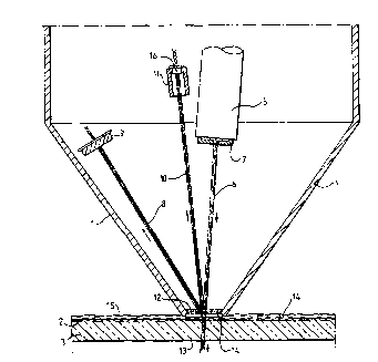
In the embodiment shown in Fig. 3, a waterproof
metal housing 1 is located during the developing
process above the coating layer 2 of a horizontal
glass master disk 3. Mounted in the bottom of the
housing 1 is a synthetic sapphire window 4. An
encapsulated solid-state laser diode forms a light
source 5, which emits a collimated light beam 6 of
wavelength 670 nm. A circular mask 7 restricts the
diameter of the light beam 6 to about 1 mm. The laser
diode source 5 is set at a small angle, about 5-10,
to the vertical, in order to avoid reflected liyht
W094/~343 ~ PCTIGB94/00720
19
passing back into it. The housing 1 is oriented
radially with respect to the master disk 3, so that
(in the presence Gf developed pits in the coating
layer 2) the first-order diffracted beam 8 lies within
~ 5 the plane of the drawing and r~ch~-~ the photodiode
sensor 9. The sensor 9 is large enough to intercept
the beam 8 for any allowable value of the track pitch
recorded on the disk 3. (A track pitch range of 1.5 -
1.7 ~m corresponds to an angular range of 3.5, or
only 3 mm at a detector distance of 50 mm.)
The reflected zero-order beam 10 is intercepted
by an internally blackened absorbing cup 11, in order
to minimise scattered light which might reach the
detector 9. Optionally a zero-order beam detector 16
may be cont~inp~ within the cup 11, so that the first-
order beam may be measured as a fraction of the zero-
order re~ing. However, it is usual for the output of
the laser diode 5 to be stab~ by a local fe~h~ck
loop, so that it will be sufficiently constant for
process control purposes without direct measul.~ -~t of
the zero-order beam lO.
Preferably an aperture 12 is positioned close to
the window 4, so as to ~l~v~l~t light scattered back
from the lower surface 13 of the master disk 3 from
re~rhing the detector 9.
The window 4 should be close enough to the
coating layer 2 to ensure that the developing fluid 14
wets the window 4 and fills the space between it and
W094/~343 PCT/GB94100720
2 1 ~
coating layer 2. A spacing of 0.5 mm is ~^~.h~n i cally
practicable. To encourage the fluid to fill the
space, the sensor should be placed close to and
"downstream" (in the direction of disk rotation) from
the developer dispensing nozzle. Preferably the
~ncor is att~-h~-A to the same arm which SU~l~S the
nozzle. In the preferred embodiment the nozzle
disp~n~c developer over a range of radii on the disk
covering at least the recorded ~loylam area of the
disk (23-58 mm in the case of Compact Disc), and the
optical sensor directs the light beam 6 to a radius on
the disk towards the bottom end of this range (perhaps
30 mm), so that valid r~A; ngs are obtA; ~A even on
those occasions when, for economy in mastering time,
the recorded area ends at a small radius.
The choice of synthetic sapphire for the window
4 is detel ;neA both by its resistance to chemical
attack and by its scratch resistance. Developing
solutions are usually alk~l~ne, and are found to
attack and cloud a glass window over a period of use.
A window with a good st~nA~rd of polish should be
selected, and its upper surface may advantageously be
given an anti-reflection coating, to reduce light
scattered back to the detector 9 from the incident
beam 6. Owing to the high refractive index of
sapphire, a simple quarter-wavelength coating of
magnesium fluoride is suitable for this purpose.
Fig. 4 shows a general view in elevation of a
W094/~343 215 ~ PCT/GB94/00720
21 \~ J; .l~-
developing arrangement incorporating the sensor of
Fig. 3. The master disk 3 rests on a tripod 30 which
rotates on a boss 31. Two arms, 32 and 33, are
retracted while 10A~ ~ ng the disk 3 but are in the
~ 5 positions shown during developing. An arm 32 can
dispense developer through a fan-chApe~ nozzle 34.
Arm 33 can dispense r~ nR~ ng water through a similar
nozzle 35. The sensor housing 1 is mounted h~h~ n~ the
nozzle 34, with its sapphire window 4 close to the
coating layer 2 on the upper surface of the disk 3.
In the arrangement shown, the sense of rotation of the
disk 3 is anti-clockwise when viewed from above, so
that the developer tends to be carried from the nozzle
34 towards the ~nC~r unit.
The process sequence may begin with rinsing water
from nozzle 35 followed by developing fluid from
nozzle 34, and then swit~h; ng back to rinsing water
from nozzle 35. The nozzle 34 is retracted during the
final rinse. After a thorough rinse, the disk 3 is
spun dry at high speed. The time at which the flow of
developing fluid is replaced by a flow of rinsing
water is determined electronically on the basis of the
output of the first-order light beam detector 9, as
described below.
Fig. 5 shows a cross-sectional view of the sensor
housing 1 next to the dispense nozzle 34. It can be
seen from Fig. 5 that the housing 1 and the nozzle 34
form an integral unit with the unit 34 being shaped so
W094/~343 PCT/GB94/00720
, 2l~gla~ S
22
that the outlet 41 thereof is adjacent the end of the
housing 1 ContA i n i ~g the window 4. The detector (not
shown in Fig. 5) and the -ource 5 are cont~ ne~ within
the housing 1, as has previously been mentioned with
reference to Fig. 3.
Fig. 6 shows a R~CO~ embodiment in which the
optical sensor unit is combined with the dispense
nozzle 34. The layout of the laser diode 5, the
aperture 7, the detector 9 and the absorber 11 are all
similar to that shown in Fig. 3, and correspnn~ ng
parts are indicated by the same reference numerals.
In the c~co~ embodiment of Fig. 6, the incident
beam 6 from the laser diode 5, the zero-order
reflected beam lO and the first-order diffracted beam
8 all pass through a transparent body 35 forming a
wall of the nozzle 34, which is made from acrylic
plastics, rather than through air. Instead of a
window 4 there is a flat, polished lower face 40 to
the nozzle 34. The lower face 40 extends equally on
either side of a slot 42 through which developing
fluid is dispensed, so that the developing fluid is
forced out between the lower face 40 and the coating
layer 2, thus forming an optically homogeneous part of
the light path to and from the coating layer 2. The
clearance between the lower face 40 and the coating
layer 2 may be about 2 mm.
The incident beam 6 enters the plastics body 35
from the laser diode 5 and the first-order beam 8
W094/~343 ~1~91 0~ PCT/GB94/00720
23
leaves it through further polished faces in the
plastics body 35. Preferably an absorber similar to
the absorber 11 in Fig. 3 is formed by cutting away
material of the body 35 to leave a stub, the rough
~ 5 outside surface of which is painted black.
Fig. 7 shows a further embodiment in which an
optical ~n-Qo~ unit is combined with a dispenser
nozzle 34. The layout of the laser diode 5, the
aperture 7, the detector 9 and the absorber 11 are
again similar to that of Fig. 3, but the light beams
6, 10 and 8 pass through developing fluid within the
nozzle 34 itself, r~Ach~ ng the disk surface 2 through
a slot 43 in the nozzle 34 through which the
developing fluid also emerges. The slot 43 is made
somewhat wider (perhaps 2 mm) than the slot 42 in the
embodiment of Fig. 6, the beam 6 being carefully
aligned so as to pass centrally through it. At least
one polished windows 50 are provided for the beam 6 to
enter and the beam 8 to leave the cavity of the nozzle
34. It is possible to provide separate windows 50 for
the beams 6 and 8, but a single window 50 may be
sufficient. There is a t~nA~n~y for bubbles to form
within the nozzle 34; so the liquid flow must be so
directed that bubbles, if any, settle at points which
do not interrupt any of the beams 6, 10 or 8.
Any of the sensor arrangements shown in Figs. 3,
5, 6 and 7 may also be employed in a tr~n~;ssive
system. In such a case the laser diode source 5 need
W094/~343 2 ~ PCT/GB94/00720
24
not be within the sensor assembly. Instead, the
incident light beam from the laser diode is directed
from underneath through the glass disk 3 into the
window 4, the face 40, or the aperture 43 as
appropriate. If a tripod 30 is used to hold the disk
3, allowance can be made in the detecting electronics
for the periodic interruption of the beam by the legs
of the tripod 30; alternatively, the tripod may be
dispensed with if the disk 3 has an att~çhe~ centre
boss, so that it can be mounted directly onto the boss
31.
Fig. 8 shows a block diagram of an electronic
system for generating from the output of detector 9 a
signal for terminating development, in accordance with
the third aspect of the invention. The laser diode
source 5 is equipped with a modulation input which
allows the light power to be switched between a high
value and a low value in response to an externally
applied signal. An oscillator llO generates a square-
wave signal 111, at a frequency in the order of 10kHz, which is applied both to the said modulation
input of the laser diode source 5 and to the reference
input of a phase-sensitive detector or multiplier 112.
Meanwhile the output of the detector 9 passes through
a preamplifier 113, an a.c. coupling 14 and a further
amplifier 115 to yield an a.c. coupled signal which is
fed to the signal input of the multiplier 112. The
output 116 of the multiplier 112 is filtered by a low-
~ W094/~343 2 ~ ~ g 1~ ~ PCT/GB94/00720
25pass filter 117 so as to remove high-frequency
components associated with the oscillator signal 111.
The filtered output 1~8 is suitably amplified by an
amplifier 119 whose output 120 is applied to one input
~ 5 of a comparator 121, the other input of which is a
reference voltage 122 derived from a potentiometer
123. The output 124 of the comparator 121 is a signal
which, when the detected first-order beam power at
detector 9 PXce~e a threshold determined by the set
voltage 122, switches so as to terminate development.
A zero-adjusting voltage 125 is also applied by
the potentiometer 126 to the amplifier 119; this
enables the output 120 to be set to zero in the
absence of developed pits in the coating layer 2, thus
compensating for any light scattered into the detector
9 within the ~eQ~ hly 1, for example from the surfaces
of the window 4.
It is not necessary for the signal 111 to switch
the laser diode output on and off completely. A
moderate depth of modulation will suffice, so long as
it is stable over time.
Fig. 9 shows a refin~ -nt of the last part of the
electronic system, in which a differentiating circuit
127 lowers the reference voltage applied to comparator
121 by an amount proportional to the rate of increase
of the voltage 120. By this means the circuit can
compensate, to a fair approximation, for delays in the
operation of the various valves which terminate
W094/23343 PCT/GB94/00720 ~
~ ~ 5 ~ 26
development in response to the signal 124. The faster
the voltage 120 is rising, the lower the threshold
voltage 128, so that the comparator 121 anticipates by
a substantially fixed time interval the time at which
voltage 120 would have reached voltage 122. The
differentiating behaviour of circuit 127 is determined
mainly by Cl and Rl; the extra components R2 and C2
serve to limit the high-frequency gain.