Note: Descriptions are shown in the official language in which they were submitted.
WO 94/23145 PCT/CA94/001~2
TITLE OF THE INVENTION
CONCRETE FORM WALLS
This application relates to a building component
of the type which is used to build up permanent concrete
form walls in building construction.
HACRGROUND OF THE INVENTION
In conventional construction in North America
concrete walls are normally produced by constructing form
walls, pouring concrete into the space between the walls
and, upon the setting of the concrete, removing the walls.
Finishing materials are then added to the concrete walls as
required.
Typically in residential construction, concrete
basement walls will be constructed in the manner discussed
above and wood framing will be constructed on top of the
basement walls. Insulation will be inserted between the
framing members and the wall finished inside and out as
desired.
Clearly both parts of this construction are
inefficient. With respect to the concrete basement walls,
it is time-consuming and wasteful of materials to have to
remove the form walls after the basement walls are poured.
Furthermore, it is now common to insulate all basement
walls, particularly in colder climates, and framing and
insulation must be installed separately inside the walls.
The piecemeal construction which is inherent in
the wood frame part of the structure is labour-intensive
and expensive.
As a result, there have been ongoing efforts for
many, many years to provide more modular types of wall
construction from which efficiencies can be gained.
1
CA 02159318 1999-09-08
One such construction type is that with which the current invention is
concerned.
For some 15 years a system has been in use particularly in Europe which
combines a number of the operations normally associated with residential and
other
building construction to provide savings in materials, energy, etc. The system
basically comprises the use of a foam insulating material to construct
permanent
concrete form walls. The form walls are constructed and the concrete poured
and the
form walls then left in place. The concrete wall so formed need not be
confined to
basement walls but may comprise all of a building's walls. No further
insulation is
necessary, and finishing materials may be applied to the interior and exterior
of the
wall as required.
Variations on this system have been proposed to achieve various
improvements. All of the systems thus far proposed, while in may cases very
useful,
suffer from some or other disadvantages.
Against this background the present invention provides a building
component for use in such a system which when integrated into a wall
construction
offers advantages over prior art such systems.
PRIOR ART
Applicant is aware of Canadian Patent No. 1,209,364, issued in 1986
to Aregger AG Bauunternehmung. The components described in that patent include
2
CA 02159318 1999-09-08
cross members, the ends of which are disadvantageously completely embedded in
the
foam blocks.
U. S. Patent 4,967,528 illustrates a system in which the foam blocks are
joined by a series of wires and rods, some of which are used to fasten wood
strips
flush with the exterior surface of the blocks, and others of which simply
protrude
through the blocks and are held in a protruding position by slide clips.
U. S. Patent 4,516,372 illustrates a system in which the foam blocks are
joined by a series of wires and metal ties which connect with elongated
horizontal
exterior metal plates.
U.S. Patent 4,730,422 illustrates a system in which the foam blocks are
joined by plastic bridging members having small end plates fitting within
slots
embedded in the foam blocks. The slots and solid web sections within the
blocks
result in significant planes of weakness.
BRIEF SUMMARY OF THE INVENTION
It has now been discovered that substantial advantages can be obtained
where the building component used to build up a concrete form wall comprises
bridging
2a
WO 94/23145 ~ _ $ PCT/CA94100172
members which extend entirely through the foam blocKs to
terminate in a plate which abuts the outside surface of the
blocks.
Thus, the invention provides a building component
comprising first and second high density foam panels each
having inner and outer surfaces, top and bottom, and first
and second ends, the panels arranged in spaced parallel
relationship with their inner surfaces facing each other,
and at least two bridging members extending between and
through and molded into the panel members, each bridging
member comprising a pair of elongated end plates oriented
in the top to bottom direction of the panels and abutting
against the outer surfaces of the panels, and at least one
web member extending between and rigidly connected to the
end plates, each web member oriented in the top to bottom
direction of the panels and having a height substantially
less than the height of the panels.
BRIEF DESCRIPTION OF THE DRAWINGS
In drawings which illustrate embodiments of the
invention:
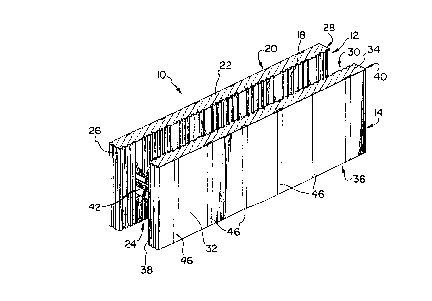
Figure 1 is a perspective view of a building
component according to the invention.
Figure 2 is a top plan view of a building
component according to the invention.
Figure 3 is a top plan view of another embodiment
of the building component according to the invention.
Figure 4 is a perspective view of a bridging
member for use in the invention.
Figure 5 is a side view of the bridging member of
Figure 4.
Figure 6 is an end view of the bridging member of
Figure 4.
Figure 7 is an end view of a building component
according to the invention incorporating the bridging
member of Figure 4.
3
WO 94/23145 ~ ~, ' ~ PCT/CA94/00172
Figure 8 is a perspective view of a series of
protrusions and interconnecting walls for use on the top of
a building component according to the invention.
Figure 9 illustrates a series of protrusions and
depressions for use on the bottom of a building component
according to the invention.
Figure 10 is a perspective view of a partially
constructed wall in accordance with the invention.
Figure 11 is a cross-section through a part of a
building site including a wall constructed utilizing the
building component of the invention.
Figure 12 is a perspective view of a building
component according to the invention illustrating the use
of rebar.
While the invention will be described in
conjunction with illustrated embodiments, it will be
understood that it is not intended to limit the invention
to such embodiments. on the contrary, it is intended to
cover all alternatives, modifications and equivalents as
may be included within the spirit and scope of the
invention as defined by the appended claims.
DETAILED DESCRIPTION OF THE PREFERRED EMBODIMENTS
The building component 10 comprises first and
second foam panels 12 and 14 secured together by at least
two bridging members 42.
Panel 12 comprises inner and outer surfaces 18
and 20 respectively, top and bottom 22 and 24 respectively,
and first and second ends 26 and 28. Panel 14 comprises
inner and outer surfaces 30 and 32, top and bottom 34 and
36, and first and second ends 38 and 40.
The panels 12 and 14 are preferably expanded
polystyrene. Subject to indentations and protrusions of
minor height to be discussed below, the panels are of
uniform rectangular cross-section. In a typical case each
4
_ 21 5 9 3 1 g --f
panel may be 122 cm. (48 inches) long, 42.5 cm. (16 % inches)
high and 7 cm. (2 5/8 inches) thick.
As indicated in Figure 3 , panels 12a and 14a may be
modified for specific purposes. The Figure 3 embodiment
illustrates a corner section.
Bridging members 42 comprise a pair of elongated end
plates 44 and 46 joined by at least one web member 48. In the
preferred configuration bridging members 42 each comprise a pair
of web members 48 and 50.
As illustrated, for example, in Figure 1, the end
plates 44 and 46 abut against the outer surfaces 20 and 32 of
panels 12 and 14 respectively. As best illustrated in Figure
7, end plates 44 and 46 are preferably recessed into surfaces
and 32 and are substantially flush with those surfaces.
15 Substantially flush inherently means that, because the end
plates are molded in place, if the end plates are recessed
slightly below the outer surfaces 20 and 32 of panels 12 and 14,
the end plates will be covered by a thin layer of foam. End
plates 44 and 46 are preferably oriented in the top to bottom
20 direction of panels 12 and 14. In the normal position of use,
this is the vertical direction.
In the preferred configuration of bridging members
42,as best illustrated in end view in Figure 6, web members 48
and 50 are offset relative to each other in the top to bottom
direction and in the first end to second end direction of panels
12 and 14. In the normal position of use those offsets are
respectively in the vertical and horizontal directions.
The web members 48 and 50 preferably include
reinforcing ribs 52 and 54 extending longitudinally of said web
members between end plates 44 and 46. As well, bridging members
42 preferably include reinforcing webs 56 and 58 between web
members 48 and 50. Further central reinforcing webs 60 and 62
are preferably provided toward the centre of web members 48 and
50.
5
2159318
In the preferred embodiment reinforcing members 64 and
66 extend from an upper edge 68 of web member 48 to end plates
44 and 46 respectively. Similarly, reinforcing members 70 and
72 extend from lower edge 74 of web member 50 to end plates 44
and 46 respectively.
5a
s0.~~1
WO 94/23145 ~~ ~ ~ ~ ~ ~_ ~ PCTICA94/00172
Finally, the bridging members 42 are preterably
provided with a series of hooked structures 76 on upper
edge 68 of web member 48 and lower edge 74 of web member
50. These members serve as illustrated in Figure 12 to
support steel reinforcing bars such as rebar 78.
Each bridging member 42 preferably comprises a
single integral unit. These members are preferably of
plastic. The preferred plastic is high density
polyethylene, although polypropylene and other suitable
polymers may be used.
The bridging members 42 are molded into the
panels 12 and 14 in the course of producing the panels. As
best seen in Figure 7, the end plates 44 and 46 are
preferably of substantially equal height to the panels 12
and 14 and are flush with the top and bottom of the panels,
subject to the vertical joining means on the panels to be
discussed below.
The reinforcing members 64 and 66, and 70 and 72
join their respective webs 48 and 50 at points 80, 82, 84
and 86 respectively, outside of the inner surfaces 18 and
respectively of panels 12 and 14.
As illustrated in Figures 10 and 11, a series of
components 10 are built up to form a wall 88. Initially a
series of components 10 are stacked to form a hollow wall
or concrete form after which concrete 90 is poured into the
hollow part of wall 88 to complete the wall.
In order to facilitate the stacking of the
components l0, the panels 12 and 14 are provided on the top
thereof with a series of plugs 92 joined by low walls 94
30 (Figure 8); and on the bottom 24 and 36 thereof with a
mating series of plugs 96 and walls 98 (Figure 9). The
plugs 92 and 96 are offset relative to each other, such
that when the bottom of one component 10 is placed on the
top of a lower component 10, the plugs 92 and walls 94 of
the upper component mate with the plugs 96 and walls 98 of
the bottom of the upper component to form a tight seal to
6
CA 02159318 1999-09-08
prevent leakage of concrete during wall formation and of energy through the
completed wall.
As best illustrated in Figures 2 and 3, the inner surfaces 18 and 30 of
panels 12 and 14 respectively are preferably provided with a series of
indentations
100. Concrete being poured into the hollow wall will flow into indentations
100 and
enhance the bond between panels 12 and 14 and concrete 90.
With reference to Figures 10 and 11, the manner of adapting the wall to
building construction is illustrated. The wall 88 in Figure 10 can be seen to
be
constructed from a series of offset components 10. The offset is clearly
preferred in
order to provide enhanced joint strength. In the typical component discussed
earlier,
of 122 cm. (48 inch) width, the bridging members 42 will preferably be spaced
on 20
cm. (8 inch) centres with the two bridging members closest to the ends of the
component located 10 cm. (4 inches) from the ends. Thus, when the panels are
overlapped to form the wall, the bridging members of the various courses can
be
aligned to form continuous strips of end plates 44 and 46 over the entire
height of the
wall. This is a very significant advantage of the present system, since
interior or
exterior wall cladding can be fixed to the exterior of the end plates 44 and
46,
preferably using screws.
The typical 42.5 cm. (16 3/4 inch) height dimension mentioned earlier can
be seen to provide a wall height of 245 cm. (8 feet '/2 inch) when six courses
of
components 30 are used and taking into account the thickness of the floor 102.
The floor joists 104 can then be laid on top of the sixth course of
components 30 and the special configuration 106 of components 30 can then be
put
in place to continue the wall.
CA 02159318 1999-09-08
In the typical wall construction of Figure 11 the wall 88 is built on footing
108. Drainage is provided and parging and damp-proofing of the exterior as is
the
case with a conventional concrete basement wall.
Using the typical dimensions noted above with a panel separation of 16
cm. (6 1/4 inches) (16 cm. of concrete) the insulating value of the wall is
R26. This is
a very high rating for wall construction and thus no additional insulation is
required.
In addition to the energy-saving value of the insulation, the walls have high
resistance
to sound transmission with a sound reduction of 48DBA.
The typical component noted above will weigh only about 2.8 kgs. and so
provides a substantial advantage to tradesman building a wall.
Thus it is apparent that there has been provided in accordance with the
invention a building component that fully satisfies the objects, aims and
advantages
set forth above. While the invention has been described in conjunction with a
specific
embodiment thereof, it is evident that many alternatives, modifications, and
variations
will be apparent to those skilled in the art in light of the foregoing
description.
Accordingly, it is intended to embrace all such alternatives, modifications
and
variations as fall within the spirit and broad scope of the invention.
8