Note: Descriptions are shown in the official language in which they were submitted.
WO 94/24410 ~ PCT/FI94/00100
1
Rod cartridge for a rock drilling equipment
The invention relates to a rod cartridge for a
rock drilling equipment, the rod cartridge comprising
a rotor with guide plates for rods; end covers having
end surfaces, the rods being placeable between the end
covers; and rotation means mounted in one end cover
for rotating the rotor.
Rod cartridges are used in rock drilling equip-
ment for storing drill rods or drill pipes used in
long-hole drilling and bolts used in rock bolting. As
used in this patent application and claims, the rod
refers to drill rods and drill pipes used in long-hole
drilling or to bolts used in rock bolting. The rock
drilling equipment in turn refers in this patent
application and claims both to a rock drilling equip-
ment and to a bolting equipment used in rock bolting.
Cartridge solutions known from the prior art
typically utilize different kinds of rotating cart-
ridges comprising end plates and usually two or three
guide plates between the end plates. A rod is posi-
tioned between the end plates into slots formed in the
guide plates. By rotating the guide plates by a
mechanism based on the so-called Maltese cross prin-
ciple, the slots can be turned successively in align-
ment with a cartridge feed opening or to a feeding
position for placing rods into the cartridge and
removing them from the cartridge. This type of cart-
ridge is well-known and of a structure self-evident to
one skilled in the art, so it will not be described
more fully herein.
A problem with the prior art cartridge solutions
is that the cartridges are of such dimensions that
they can accommodate only rods of a predetermined
length. If such a cartridge is used for rods of a
WO 94/24410 PCT/FI94/00100_
2
different length, it is necessary to change fixed
cartridge structures in order that the cartridge would
operate in a desired way. This is problematic
especially when the rods are rock bolts having widely
varying manufacturing tolerances. If the cartridge is
designed for a certain rod length, rods of a greater
length cannot be stored in it, and even a few tens of
millimetres may render a rod lot unsuitable for the
cartridge. Similarly, if it is necessary to use re-
inforcing bolts and extension rods of different
lengths e.g. in underground excavations and due to
rock structures, a single equipment provided with the
prior art cartridges cannot be used with the different
lengths, as the components that should be changed to
modify the equipment are too large. As a result, it is
necessary to use two different equipment, which often
causes extra costs. A further problem with the prior
art solutions is that a change in the rod length
requires changes in the mounting of the rod gripping
arms with respect to the equipment, which involves
extra work.
The object of the present invention is to
provide a rod cartridge which can be used for storing
rods of different lengths according to the require-
ments and which is easily and rapidly adjustable for
different rod lengths. The rod cartridge according to
the invention is characterized in that one of the end
surfaces is displaceable in the longitudinal direction
of the rotor so that the distance of the end surface
from the opposite end surface is adjustable according
to the length of the rod to be used. ,
An essential feature of the invention is that
the end surface at one end of the rod cartridge and
the guide plate close to it are displaceable in the
longitudinal direction of the rod cartridge such that
WO 94/24410
r~~ ~ PCTIFI94/00100
3
the distance between the end covers can be adjusted
for the length of a rod to be used, and the guide
plates can be positioned at suitable distances to
facilitate the handling of the rod. An essential
a
feature of a preferred embodiment of the invention is
that one of the gripping/displacing arms needed for
rod handling is similarly displaceable so that rods of
different lengths can be gripped at an optimal point
with respect to the guide plates. According to the
preferred embodiment of the invention, the displace-
able end surface of the cartridge is mounted at the
end close to the rock drill and the bolt feeding
device, respectively. This ensures that the opposite
end of the rod will always be positioned at the guide
of the feeding beam or at a drill hole to be bolted so
that any aligning problems are avoided. Further
according to the preferred embodiment of the inven-
tion, the cartridge rotation machinery and rotation
motor are mounted in close proximity to the displace-
able end cover, so that the dimensions of the cart-
ridge will be as small as possible at the front end of
the feeding beam of the rock drill and the rod will be
fed in a desired way in alignment with either the
drilling axis of the rock drill or the feeding axis of
the bolting head.
An advantage of the solution according to the
invention is that the transition from one rod length
to another takes places rapidly and simply merely by
displacing the end cover and the guide plate to a
desired position. Similarly, if the rod length varies
from a predetermined value, the cartridge may also be
adjusted to the wrong rod length without any laborious
r and expensive replacement of the parts. Moreover, the
cartridge according to the invention allows a suitable
bolt length to be used at the same working site
WO 94/24410 PCTIFI94/00100
4
according to the requirements, which involves savings
in material costs.
The invention will be described more fully with
reference to the attached drawings, in which
Figure 1 is a schematic top view of a rock bolt-
ing equipment;
Figure 2 shows the rock bolting equipment of
Figure 1 in a direction A indicated in Figure 1;
Figures 3a and 3b show a rod cartridge according
to the invention in two positions adjusted for dif-
ferent rod lengths;
Figure 4 is a schematic view of a gripping arm
as seen in the direction of the turning axis;
Figure 5 is a schematic side view of another
embodiment of the invention.
Figure 1 is a schematic top view of a rock
bolting equipment. The equipment comprises one embodi-
ment of the rod cartridge according to the invention,
i.e. a bolt cartridge 1. It further comprises a bolt-
ing head 2 movable along its own feeding beam 2a, and
a rock drill 3 similarly movable along its own feeding
beam 3a. It also comprises gripping arms 4 connected
to a mounting beam 5 turnably about a shaft 6. The
bolting head 2 and the rock drill 3 and the gripping
arms 4 with their beams are connected as a single unit
to a base 7 turnable about a vertical shaft 8. Both
the base 7 and the cartridge 1 are connected to an
equipment frame 9.
Figure 2 shows the rock bolting equipment of
Figure 1 as seen in a direction A indicated in Figure
1. It appears from Figure 2 that there are two
gripping arms 4 spaced mutually so that rods (not
shown in Figure 2) placed in the cartridge 1 can be
gripped and withdrawn from the cartridge into align
ment with a hole to be bolted. In Figure 2, the parts
a
~WO 94/24410 PCT/FL94/00100
corresponding to those shown in Figure 1 are indicated
with the same reference numerals with the exception of
the gripping arms, which are indicated with the refer-
ence numerals 4a and 4b for the sake of clarity.
v
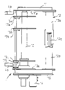
5 Figures 3a and 3b show a rod cartridge according
to the invention adjusted for a short rod and a long
rod, respectively. The rod cartridge is formed of a
central tube or Shaft 10 mounted for rotation with
respect to an upper fixed end cover 11. A tubular
support arm 12 formed of an outer tube 12a and an
inner tube 12b disposed longitudinally movably within
the outer tube is also attached to the upper end cover
11. The inner tube 12b can be secured immovable with
respect to the outer tube 12a by a squeezer 12c. The
inner tube 12b in turn is attached to another end
cover 13 within which means for rotating the cart-
ridge, i.e. a Maltese cross mechanism, is disposed and
to which a rotation motor 14 is also connected. The
other end cover 13 is positioned around the shaft 10,
and it can be displaced longitudinally of the shaft.
Guide plates 15a to 15c are also attached to the shaft
10. The guide plates are provided with slots into
which rods 16 are placed in a manner known per se. The
guide plates 15a to 15c are further provided with
retainer springs 17a to 17c which keep the rods 16 in
position in the slots. The rotation mechanism within
the other end cover 13 is attached to the shaft 10
unrotatably by means of a friction connecting sleeve
18. Similarly, the guide plate 15c closest to the end
cover 13, i.e. the bottommost guide plate in the
figure, is attached to the shaft 10 by a similar
friction connecting sleeve 19.
To adjust the length of the cartridge for a rod
to be used, the squeezer 12c and the friction connect-
ing sleeves 18 and 19 are opened. The lower end cover
WO 94124410 PCT/FI94/00100~
6
is thereafter displaced as shown in Figure 3a such
that the rod 16 will be positioned between the end
surfaces lla and 13a of the end covers 11 and 13. The
friction connecting sleeve 18 and 19, respectively, is
v
then tightened so that the Maltese cross mechanism
within the end cover 13 is connected unrotatably to
the shaft 10, and the guide plate 15c is similarly
connected unrotatably to the shaft 10. The guide
plates 15a and 15b are preferably mounted fixedly to
the shaft 10, as they need not be displaced when the
length of the rod 16 varies. Figure 3b in turn shows a
situation in which the cartridge has been adjusted for
a long rod 16'. In this case, the squeezer 12c of the
tubes 12a and 12b has correspondingly been opened
first and then the friction connecting sleeves 18 and
19, whereafter it has been possible to displace the
other end cover 13 and its motor and the guide plate
15c to the bottom end of the shaft 10. The friction
connecting sleeves 18 and 19 and the squeezer 12c
between the tubes 12a and 12b have thereafter been
tightened. In the cases of both of the figures, the
rotation of the motor 14 rotates the Maltese cross,
which rotates the shaft 10 via the friction connecting
sleeve 18. The guide plates 15a to 15c thus also
rotate, displacing the rod 16 or 16' to a position for
withdrawing the rod from the cartridge; alternatively,
in the case of long-hole drilling, for placing a
detached extension rod into an empty slot in the guide
plates 15a to 15c. Figures 3a and 3b further show how
the lower gripping arm 4b has been displaced similarly
as the cartridge end cover 13 so that it is at a suit-
able distance from the ends of the rod 16. Both of the
gripping arms 4a and 4b are connected to the shaft 6
(not shown in the figure) passing through them. The
shaft 6 is hexagonal in cross-section, but it is
~WO 94/Z4410 f~ , ' PCTIFI94I00100
7
mounted turnably to a stand 20 shown in Figure 4. The
stand 20 comprises a slot 21 for an I-shaped beam 5.
The stands 20 are attached to the beam 5 by mounting
bolts 22 so as to fix the arm with respect to the beam
5. The arms 4 are turned by turning the shaft 6 by a
power unit known per se (not shown), such as a
hydraulic motor or cylinder.
To displace the gripping arms 4, or the gripping
arms 4a and 4b shown in Figures 3a and 3b, the mount-
ing bolts 22 are opened so that the stand 20 is slid-
able along the track 5. As the gripping arms are con-
nected to the shaft 6 shown in the figure by a hexa-
gonal hole whereas they are not fixed to the shaft in
any way, they are also able to slide with respect to
the shaft 7, being thus easily and simply adjustable
to a desired position. When the gripping arm is in a
desired position, the mounting bolts 22 of the stand
20 are tightened so that the gripping arm will not
move with respect to the stand.
Figure 5 shows another embodiment of the inven-
tion in which the cartridge itself is fixed in length,
that is, the end covers 11 and 13 are interconnected
by an integral supporting arm 12. In this embodiment,
the end surfaces 11a and 13a form part of separate end
plates llb and 13b connected for rotation with the
rotor shaft 10 so that the rods 16 contained in the
cartridge will not chafe the end surfaces lla and 13a.
In this embodiment the end plate 13b is displaceable
in the longitudinal direction of the shaft 10 so as to
adjust the distance between the end surfaces 13a and
lla in accordance with the length of the rod 16. Cor-
respondingly, the guide plate 15c close to the dis-
placeable end plate 13b is displaceable in the longit-
udinal direction of the shaft 10. The end plate 13b
and the guide plate 15c may both be arranged to be
WO 94/24410 PCT/fI94/00100
8
separately attached unrotatably to the shaft either by
a friction connecting sleeve mentioned above or other
fixing means. Similarly, the guide plate 15c and the
end plate 13b may be fixed to each other, in which
case a single fixing means will suffice, such as a
friction connecting sleeve. In this embodiment, the
Maltese cross mechanism operated by the rotation motor
may be connected fixedly to rotate the shaft 10.
The invention has been described in the above
text and shown in the drawings only by way of example
and the solution is.not in any way limited to the
examples.
The rotation mechanism and the guide plate 15c
may be connected to the shaft 10 unrotatably in dif
ferent ways e. g. by a wedge provided in the shaft 10
or in some other way. Also, they may be connected in
the vertical direction of the shaft 10 by various
screw fixing means and other similar means. Corre-
spondingly, the tubes 12a and 12c may be inter-
connected in various way, depending on the applica-
tion. The outer tube 12a and the inner tube 12b may be
interlocked immovably with respect to each other by
the squeezer 12c at the free end of the outer tube
12a. In such a case, the end of the outer tube 12a
will be squeezed smaller than its diameter due to a
transverse slit 12d formed in the outer tube 12a and a
longitudinal slit starting from the transverse slit
and extending through the squeezer 12c also starting
from the transverse slit, thus fixing the inner tube
12b in position.
Furthermore, when the guide plate is provided
with a slot of an appropriate width, rods of different
diameters can be used merely by changing the springs
17a to 17c. In this way, it is possible to select the
~O 94/24410 ~ ~ PCT/FI94/00100
9
diameter as well as the length of the rods according
to the requirements in each particular case.