Note: Descriptions are shown in the official language in which they were submitted.
~ 2159678
H-190639
AIR BAG SYSTEM WITH ZINC-BASE AL10Y COMPONENTS
Field of the Invention
s The invention relates to high strength, high
temperature and high strain rate applications of a
zinc-base alloy, and more particularly to applications
of a zinc-copper-aluminum alloy in air bag system
components.
Backqround of the Invention
In a typical die casting operation, molten
metal is injected at high pressure into a fixed-volume
cavity defined by reusable water-cooled metal dies.
Within the cavity, the metal is molded into a desired
configuration and solidified to form a product
casting. The metal is injected into the cavity by a
shot apparatus comprising a sleeve for receiving a
charge of the molten metal and a plunger that advances
within the sleeve to force the metal into the cavity.
Two types of shot apparatus are known. A hot chamber
apparatus comprises a shot sleeve immersed in a bath
of a molten metal. In a cold chamber apparatus, the
molten charge is transferred, for example by ladle,
2s into the shot apparatus from a remote holding furnace.
Zinc-base alloys are commonly formed by die
casting, in large part because of a conveniently low
~ 2ls9~78
melting point. Heretofore, zinc die castings have
exhibited a microstructure characterized by soft
phases, such as the eta or alpha phases in zinc-
aluminum alloys, that lack stability even at
moderately high temperatures. As a result, such
alloys have had poor high temperature creep resistance
that has restricted their use, mainly to decorative
parts.
Rashid et al., 4,990,310 discloses a creep-
0 resistant zinc alloy including 4-11 percent copper,
and 2-4 percent aluminum. The alloy includes a
microstructure with an intimate combination of fine
epsilon and eta phases that is particularly resistant
to slip. As a result, the product die casting from
~5 the alloy exhibits improved strength and wear
resistance primarily due to the epsilon phase, but
also a dramatically improved creep resistance,
particularly in comparison to similar zinc die
castings that are substantially epsilon-free.
Commercial zinc alloys (Zamak and ZA alloys)
are used mainly for decorative applications. They are
rarely used in functional/structural applications
because their strength and/or creep properties do not
meet requirements. Instead, stronger materials like
steel are used to meet specifications. Steel parts
2~9678
are usually machined, whereas, zinc alloys can be die
cast to shape.
Furthermore, many automotive and
nonautomotive components are required to withstand
s high forces at high straln rates. At higher
temperatures (up to 150~C) the strain rate sensitivity
becomes more important since low melting metals such
as zinc alloys usually soften at this temperature.
Thus, any increase in strength to of f set this
o softening is an added value.
Some metals and alloys are strain rate
sensitive at room temperatures, but, the magnitude of
tensile strength increase is small or negligible.
Stainless steel and different aluminum alloys have
negligible strain rate sensitivity and the increase in
tensile strength was minimal. The increase in
strength is also very small with increasing strain
rate in other types of aluminum alloys. No increase
in tensile strength has been found in other nonferrous
alloys such as copper and brass.
Different hot rolled steels, increase less
than 10% in tensile strength with increased strain
rate for the same strain rate range used in our study
(105 to 10~ secl). When iron and miled steel are
2s tested at higher temperatures (up to 200~C), the
ultimate tensile strength does not increase with
2159
~78
increasing strain rate, and they lose their strain
rate sensitivity.
A variety of materials are avaiLable from
which one may attempt to successfully fashion
components from. Many automotive components are
subject to very high loads, for example during an
automobile crash. Many automotive components are
subject to high temperatures such as those components
under the hood or components which involve high
0 temperature applications under dramatic loading.
Conventional wisdom dictates that such components are
constructed from relatively expensive, heavy alloys
which often require machining.
The present invention overcomes many of the
prior art shortcomings.
SUMMARY OF THE INVENTION
The present invention includes high
strength, high temperature and strain rate
applications of a zinc-base alloy including about 83
to about 94 weight percent zinc, about 4 to about 11
percent copper and about 2 to about 4 percent
aluminum. The composition may also include minor
components such as magnesium and impurities. The
2s alloy is used to construct automotive components which
are subject to an instantaneous force between 40-500
2159678
MPa. The alloy is particularly suitable for
constructing components which are subject to such
loads under high temperatures (higher than ambient
temperature). In fact, components constructed from
the alloy have greater relative strength at higher
temperatures under sudden stress.
These and other objects, features and
advantages will become apparent from the following
brief description of the drawings, detailed
description, and appended claims and drawings.
Brief Description of the Drawinqs
Figure 1 is a cross sectional view of a cold
chamber casting zinc-aluminum-copper alloy according
to the present invention;
Figure 2 is a cross sectional view of a hot
chamber die casting machine for casting zinc-aluminum-
copper alloy according to the present invention;
Figure 3 is a graph of the ultimate tensile
strength of an alloy used to make components according
to the present invention tested at room temperature
with increasing strain rate;
Figure 4 is a graph of the ultimate tensile
strength of an alloy, used to make components
2~ according to the present invention tested at 50CC with
increasing strain rate;
CA 021~9678 1998-07-27
Figure 5 is a graph of the ultimate tensile
strength of an alloy, used to make components
according to the present invention, tested at 100~C
with increasing strain rate;
Figure 6 is a graph of the ultimate tensile
strength of an alloy, used to make components
according to the present invention, tested at 150~C
with increasing strain rate;
~ Figure 7 is a graph of the percentage
o increase in ultimate tensile strength of the alloy
with increasing temperature;
Figure 8 is an illustration of a vehicle
steering system having an air bag module according to
the present invention;
Figure 9 is a partial sectional view of an
air bag module according to the present invention; and
Figure 10 is an enlarged view with portions
removed of a wireless electric lead as shown in Figure
7.
Detailed Description
Rashid et al U.S. Patent No. 4,990,310
describes a creep resistant die casting form from a
zinc-base alloy including about 4 to about 12 percent
copper and about 2 to about 4 percent
~ 2159678
aluminum. That zinc, copper and aluminum alloy is now
known as ACuZinc~. It has recently been discovered
that the strength of a zinc-base alloy containing 4 to
about 12 weight percent copper and about 2 to about g
s percent aluminum, prepared by the die casting process
disclosed in the '310 patent has increased strength
when the strain rate is increased by dynamic and fast
loading. The strength of the component formed from
the ACuZinc~ alloy is increased about 50 percent at
l~ room temperature, about 68% at 50~C.; about 220% at
100~C.; about 2600% at 150~C when the loading rate was
increased from 10-5 to 10~ sec1
The ACuZinc~ alloys which exhibit such high
strength under dramatic loading and temperature,
15 include a duplex structure having a skin of fine
grains of epsilon-phase (copper rich) ranging between
1-2 microns embedded in a matrix of ~ (zinc rich) and
Alpha phase (aluminum rich). The inner portion of the
component contains larger grain sizes of the epsilon
phase.
The ACuZinc~ die casting is prepared as
follows. A die casting was formed of a zinc-base,
copper-aluminum alloy (ACuZinc~) using a conventional
cold cha~ber dle casting machine shown schematically
2s in Figure 1. The machine 10 may include a movable
2159678
platen 11 and a statlonary platen 13. Die halves 12
and 14 are mounted on platens 11 and 13, respectively,
and cooled by water circulated through passages (not
shown) therein. In the closed position shown in the
s figure, die halves 12 and 14 cooperate to define a
fixed-volume die cavity 16 suitably sized and shaped
for producing a casting of a desired configuration.
At appropriate times during the casting cycle, platen
11 moves relative to platen 13 to part die halves 12
and 14 along a plane indicated by line 18 for e~ection
of a product casting. Machine 10 also includes a shot
apparatus 20 comprising a generally cylindrical shot
sleeve 22 that communicates with cavity 16. Sleeve 22
includes an inlet 24 for admitting a molten metal
ls charge 26 poured, for example, from a suitable ladle
28. A hydraulically driven shot plunger 30 is
slidably received in sleeve 22 and advances toward the
die sections for forcing metal from sleeve 22 into
cavity 16.
In accordance with a preferred embodiment of
this invention, charge 26 was composed of an alloy
comprising 10.0 weight percent copper, 3.6 weight
percent aluminum, 0.03 weight percent magnesium and
the balance zirc and impurities. The charge was
2s poured at a temperature of about 532~C into shot sleeve
22 through port 24. Slot plunger 30 was advanced to
21S9678
inject the charge into casting cavity 16. The cavity
surface temperature was about 140~C. After ~illing the
die cavity, the shot plunger continued to apply a load
of 1340 kilograms for about 12 seconds. Within the
die cavity, the metal cooled and solidified,
whereafter the die sections were parted to eject a
product casting.
In a second embodiment, zinc die castings of
this invention were manufactured uslng a hot chamber
o die casting machine 50 shown schematically in Figure
4. Machine 50 comprises water-cooled die halves 52
and 54 mounted on a stationary platen 53 and a movable
platen 55, respectively, adapted for moving die halves
between a closed position shown in Figure 4 wherein
the die halves cooperate to form a casting cavity 56
and an open position wherein the die halves are parted
along a plane indicated by line 58 for e~ection of a
product casting. In accordance with common hot
chamber die casting process, die casting machine 50
comprises a shot apparatus 60 formed of a goose neck
sleeve 62 partially submerged in a molten metal bath
64 contained in melting pot 63. Shot apparatus 60
further comprises hydraulically driven plunger 68
slidably received in goose neck 62. When plunger 68
2~ is in a retracted position shown in the figure, a
charge of molten metal from bath 64 fills goose neck
~ 215~7~
62 through an inlet port 66. For casting, plunger 68
is driven downwardly to force molten metal through
sleeve 62 into die cavity 56.
In accordance with this invention, a hot
s chamber die casting was formed of an alloy containing
5.0 weight percent copper, 3.0 weight percent
aluminum, 0.035 weight percent magnesium and the
balance substantially zinc. The temperature of the
charge was about 490~C. The casting cavity surface
temperature was about 150~C. During injection, the
melt was subjected to a pressing load of 62
kiloPascals. Other materials with 3.5-12.0 weight
copper, 1-8 weight Al and 0.01-0.06 Mg of composition
will have similar effect of strain rate on loading at
the above tested composition.
Chemical composition of the test specimens
used in this investigation was as described above.
Specimens tested were 25.4 mm long x 5.33 mm diameter
in the gauge section, and were used in the as-diecast
condition, with the as-cast surface intact. Tests
were performed using an Instron universal testing
machine which has the capability of maintaining
constant cross-head speed. ~oad-elongation data were
recorded automatically during the tests. The
2s specimens were loaded to failure and ultimate tensile
strength calculated. Tests were conducted at four
' ~ 21S9678
different temperatures (room temperature, 50~C, 100~C,
and 150~C) using a temperature controlled chamber to
insure constant temperature during the test. Cross-
head speeds used were 0.02, 0.2, 2, 20, 200 and 500
s mm/min, which provided strain rates ranging from 1.3 x
10-5 to 3.2 x 10~1 sec~1.
Figure 3 shows the variation of ultimate
tensile strength (UTS) of this alloy at room
temperature (20~C) with increasing strain rate. It was
o found that when the strain ratç is increased from 105
to 10~ sec , the UTS increased from 280 to 440 MPa
(57%)-
The percentage increase in ultimate tensile
strength with increasing strain rate was found to be
much higher when the specimens were tested at higher
temperatures. At 50~C the UTS increased from 250 to
420 MPa (68%) for the same increase in strain rate
(Figure 4). The percentage increase was 220% at 100~C
(Figure 5), and 2600% at 150~C (Figure 6).
The above data is replotted in Figure 7 to
show the percentage increase in UTS with temperature
when the strain rate increases from 105 to 10~ secl.
It is clearly shown that the strain rate sensitivity
increases dramatically above 80~C.
~ 21~ 7~
12
A typical microstructure of the alloy has a
duplex structure consisting of an outer skin of fine
grains of ~-phase (copper rich) ranging between 1-2
microns embedded in a matrix of ~ (zinc rich) and a
s phases (aluminum rich). The microstructure is much
coarser inside the specimen.
In this investigation, we discovered that
ACuZinc~ alloys will strengthen when the strain rate
increases between 105 to 10~ sec1, and this increase
lo is greater at higher temperatures. This behavior is
unexpected and has not been reported before. Alloys
such as aluminum, copper, stainless steel are not
strain rate sensitive when tested at room temperature.
The strain rate sensitivity of pure iron and steel
alloys is much smaller than that found in ACuZinc~
alloys at room temperature. Iron and steels lose
their strain rate sensitivity when tested at higher
temperatures (reported up to 200~C).
With this discovery ACuZinc~ die cast alloys
can be used with confidence at higher temperatures for
components in fast loading/high temperature
applications. The unexpected increase in strength
with strain rate during high temperature testing
provides increased potential use of these parts in
2~ many applications such as for under-hood automotive
' ~ 215g678
applications use, such parts as connectors, brackets,
support, and engine mounts, which can be subjected to
a combination of high strain rates and high
temperature conditions as during an impact in a
s collision. It may also be applicable in other systems
such as the air bag system and components and
attachments used to secure the seat belt assembly.
Seat actuators, and components in the steering
columns, gears, racks, supports, and housing are other
o potential components, where increase strength at high
rate de~ormation is important.
21~9678
Data:
In Table 1 the Ultimate Tensile Strength of
the alloy tested is compared to commercial zinc base
alloys (Zamak 3 and ZA 8 alloys) tested at two
s different temperatures and strain rate of 1.312 x 10 3
secl. The results show that the ultimate tensile
strength at 50~C for ACuZinc~ was the same as that
measured at room temperature (20~C). 351 MPa at 50~C
(100~F) compared to 347 MPa at room temperature.
However, the Ultimate Tensile Strength of commercial
Zamak 3 alloy was 253 MPa at 20~C but 227 MPa when is
tested at 50~C; for ZA 8 alloy it was 336 MPa at 20~C
vs. 283 MPa when tested at 50~C.
Table 1
Temperature Alloy Tested Zamak 3 ZA 8
UTS,MPa UTS,MPa UTS,MPa
20~C 347 253 336
50~C 351 227 283
Components constructed from the ACuZinc~
alloy provide resistance to deformability and damage
when the components are under mechanical loadings at
high strain rates or when they are impacted as in a
14
' ~ 21~9678
crash or collision situation. Even though ACuZinc~ is
a zinc-base alloy, it has surprisingly been discovered
that high load bearing components manufactured from
ACuZinc~, that is, components subjected to loadings
s between 40-500 MPa, exhibited a dramatic improvement
in strength. Examples o~ high load components include
seat belt assembly components, actuators, gears, seat
actuators, seat racks, racks, motor mounts, electronic
housings, and other components which must remain
lo functional during an automotive collision.
Nonautomotive components, subject to
dramatic load increases and at high temperatures may
be made from the ACuZinc~ alloy. For example,
components for hand tools such as drills, may be
1~ constructed from ACuZinc~ alloys. Such materials are
often subject to high loads and temperatures. For
example, when a saw or drill having ACuZinc~
components hits a nail or other material, the ACuZinc~
components actually become stronger under such high
loadings and temperatures.
~ any of the components in an automobile,
such as those under the hood in the engine
compartment, are subject to high temperatures up to
150~C. In an automobile collision, it is important for
2~ these components remain functional so that the
~ ~ 215g678
automobile can continue to operate or can be driven
away from the scene of an accident. Accordingly,
components such as hose couplings, battery connectors
and extensions, engine brackets and mounts may be
s constructed from ACuZinc~. Particularly important are
housings for electronic components, such as the
automotive computer module housing which may be
constructed out of ACuZinc~. Upon impact in a
collision, an ACuZinc~ electronic housing is much more
likely to survive the impact than other materials. If
the computer module is damaged, the car will not be
driveable. Exhaust system components such as fuel
burning catalytic converter heater burner nozzles, air
swirlers and combustion chambers may be made from
ACuZinc~.
Nonautomatic electronic components may be
housed by structures formed from ACuZinc~ material
when the housings are subjected to high loads and
temperatures. For example, an electronic housing for
a cluster bomb is subject to high loadings and high
temperatures during the first explosion of the bomb,
which sends smaller bombs in a variety of directions.
The timers within the electronic components of each
of the smaller bombs must survive the initial
2s explosion in order for the smaller bombs to function
21S9678
properly. Electronic housings made from ACuZinc~
provide an improved housing with greater strength
during dramatic loads and high temperatures.
In a preferred embodiment, the lnvention
s includes a vehicle air bag system or module with
select components made from an alloy according to the
present invention, ACu~inc~. The following is a
detailed description of a suitable air bag system.
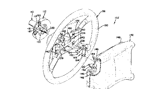
Referring to Figures 8, 9, and 10 the horn
activation and steering wheel assembly 107 of the
present invention has a steel shaft column 110. The
column 110 transmits a torsional input from the drive~
of the vehicle to a steering system (not shown). The
column 110 is also electrically connected to the
ground of the electrical system of the vehicle.
Mounted on the column 110 is a horn contact plate 112.
The horn contact plate has an electrically conducting
portion 114 typically fabricated from brass or other
highly conductive material. ~he conducting portion
2~ 114 is generally shaped as a flat annular ring and is
electrically isolated from the column 110 by an inner
mounting polymeric piece 116. Removed from the
drawing for clarity of illustration, a coil spring
captured between a shoulder (not shown) on the column
2s 110 and an internal flange portion (not shown) in a
bore 118 of the inner mounting member urges the horn
~ 21~9678
18
contact plate 114 toward a threaded end 120 of the
column 110.
Fitted over a splined portion 122 of the
column is a hub 124 of a steering wheel 126. The hub
s 124 has weldably connected thereto four spokes 128
which connect with an outer rim 130 of the steering
wheel. A nut 132 is threadably engaged onto the
column 110 to retain the hub 124 axially upon the
column 110.
Also fixably connected to the column 110 by
the nut 132 is a steering wheel mounting plate 134.
The steering wheel mounting plate 134 has two holes
136 allowing it to be fixably connected to the hub 124
by virtue of cap screws (not shown). Additionally,
the steering wheel mounting plate 134 has a larger
hole 138 for purposes to be described later and four
outer mounting holes 140 along its outer perimeter.
Lastly, the steering wheel mounting plate 134 has a
central hole 142 allowing for penetration of the
threaded end 120 of the column. The steering wheel
mounting plate 134 is electrically connected with the
column 110.
Mounted to the steering wheel mounting plate
is a module 142. The module 142 includes a module pad
2s retainer 144 which is connected by rivets 146 with a
module base plate 148. Fixably connected to the
18
. ' ~ 2159~7g
19
module base plate 148 are four pro~ecting pins 150
having surrounding annular bells 152. Each pin 150
has a ball lock 154. The module base plate 148 also
mounts an SIR canister or inflator 155, a fabric air
s bag 156 and a cover 158. The inflator 155 carries
chemicals which are selectively pyrolyzed upon impact
of the vehicle. The pyrolysis of the chemicals
rapidly form gases which flow out of holes formed in
the inflator and fill the air bag 156. The pyrolyzed
o chemicals reach temperatures of 250~C-500~C or higher
in 60 milliseconds or less. The inflator 155 and
other components of the air bag system may be heated
up to above 500~C upon pyrolysis of the chemicals on
the inflator 155 while the inflator 155 and other
S components are exposed to pressures of 40-500 MPa and
above.
The module 142 is biased to a first position
from the steering wheel mounting plate 134 by springs
160 which push up against the top portion of the bells
152. The springs 160 bottom end (as shown in Figure
2) presses against the steering wheel mounting plate
134. A top portion 162 of the pin 150 is surrounded
by an elastomeric or polymeric grommet 164. Thus, pin
150 and steering wheel mounting plate 134 are
2s electrically isolated from the module base plate 134.
The module pad retainer 144 has a central opening 166
19
' ~ 21~9678
which allows for penetration of the threaded end 120
of the column.
To electrically connect the module pad
retainer 144 with the conducting portion 114 of the
s horn contact plate, there is provided a wireless
electric lead 168. The wireless electric lead has a
first contact 170 which electrically connects with the
conducting portion 114 of the horn contact plate and a
second lead 172 which makes continual contact with the
module pad retainer 144. The ends 172 and 170 are
spring biased away from one another by a conducting
coil spring 174 fabricated from a tin-coated musical
spring steel. The coil spring will typically have a
spring rate of approximately two pounds per inch,
having 114 coils per inch with a diameter of 0.5 mm.
Each lead has a spring mounting stud 176 and stud
members 178 which are captured in longitudinal slots
180 provided in a polymeric tubular insulator 182
which surrounds the spring 174. The insulator 182 at
its opposing end has a slot 184 provided for
installing the ends 170 and 172.
Electrical lead 168 is positioned through a
slot provided in the hub 124 and penetrates through
the inner hole of an SIR exciter coil 186. To align
2s the lead 168, there is providèd a tower member 187.
As shown, tower member 187 is one piece. However, it
~ .
2159678
may be desired to comprise several different pieces.
If desired, the tower 187 may be made to be integral
with the insulating portion 116 of the horn contact
plate 112. Not shown for clarity of illustration is a
s steering lock and an associated insulator which
typically will abut an end of the horn contact plate
toward the column end 120 (with the exception of that
portion of the horn contact plate which is contacted
by the lead 168).
0 Referring to Figure 1, a void 188 is
provided to allow a wire (not shown) from the coil 187
to be connected to the inflator 155. To actuate the
horn, the module 142 will be pushed downward against
the biasing of spring 160 to cause the bell housing
152 to contact the steering wheel module plate at
least at one of its four locations. The above action
causes the module 142 to come into its second position
wherein it is electrically connected to the steering
wheel mounting plate 134.
Current then flows from a source of electric
energy 196 to a horn 198 located remotely through a
lead wire 199 shown schematically to the conducting
portion 114 of the horn contact plate to the first
lead 170. Current then flows through the conducting
2s wire 174 to the second lead 172 to the module pad
retainer 144, through rivet 146 to module base plate
21
' ~ 2159678
148 to bell housing 152 to steering wheel mounting
plate 134, to the nut 132, column llO and then to
ground, completing the current and thereby activating
the horn.
The electric lead 168 eliminates a previous
lead wire which connected the horn contact plate
conducti~g portion 114 to the module pad retainer 166.
This wire had to be sufficiently long enough to allow
it to be attached to the module pad retainer 144
o before assembly of the module 142 to the steering
wheel mounting plate 134. The length of the wire had
to be sufficiently long to be easy to assemble.
However, a sufficient length was found to be
inconvenient due to the proper placement of the lead
wire after the module 142 was assembled to the
steering wheel mounting plate 134. If not done
correctly, such a wire could cause rattling
vibrational noise which could be an irritant to an
occupant of the vehicle. Also, the prior wire could
short or get cut on a sharp edge of the steering wheel
assembly.
To assemble module 142 to the steering wheel
mounting plate, the pins 150 are aligned with the
holes 140 in the mounting plate and simply pushed
2s inwardly, allowing the ball locks 152 to then pop back
' ~ 21~9678
23
out, retaining the module plate to the steering wheel
mounting plate 134.
The improvement in the above-described
S system according to the present invention is that
components subjected to high strain rate and high
temperatures are made from an alloy of the present
invention, namely ACuZinc~. The projecting pins 150,
annular bells 152 and in~lator 155 may be made from
0 the alloy of the present invention, ACuZincTM. The
inflator 155 may be die cast to final dimensions ~rom
ACuZinc~. When the chemicals held in the inflator 155
are ignited, the inflator is subjected to a very high
rate of strain and at a very high temperature. Zinc-
based alloys would not be expected to be suitable forthis application or use. 1ikewise, the projecting
pins 150, and annular bells 152 are subjected to very
high strain rates and temperatures when the air bag
system goes of~.
23