Note: Descriptions are shown in the official language in which they were submitted.
216032S
--1--
llOOD PPOC~PING APPARATUB WITH IMPACT }L~IBR
BACKGROUND OF THE lNV~N'l'lON
The present invention relates to harvesting and
processing timber, and, more particularly, to a method
and apparatus for delimbing felled trees.
Conventional methods and apparatus have been
developed to harvest st~n~ing trees and to thereafter
delimb felled trees. Once such apparatus was disclosed
in U.S. Patent No. 3,999,582 which utilizes opposing
pivoting shear blades operated by associated hydraulic
fluid actuators. The shear blades are brought into
contact with the tree and are moved by the actuators
toward each other to shear the tree. The device also
includes encircling members which encircle the tree stem
and, upon upward movement thereof, delimb the tree stem.
Other conventional delimbing methods include sawing,
chipping, or ripping the limbs by circular motion of a
cutting device.
The aforementioned delimbing methods work well
in the soft wood, but are not as effective in hard
woods. For example, significant force is required to
shear limbs of hard wood. Further, the conventional
delimbing methods, such as the use of chain saws,
creates an extremely hazardous task.
Accordingly, need exists to provide a method
and apparatus for delimbing both soft wood and hard wood
felled trees, without requiring manual chain saw duty or
a device which requires significant force to delimb a
tree.
SUMMARY OF THE INVENTION
An object of the present invention is to
fulfill the need referred to above. In accordance with
the principles of the present invention, this objective
is obtained by providing an apparatus for delimbing tree
limbs of a felled tree. The apparatus includes housing
structure constructed and arranged to be movable to a
tree processing location. Support and feed structure is
constructed and arranged with respect to the housing
216032~
~ -2-
structure to support a stem portion of the tree while a
limb thereof is severed, and to move the stem portion
progressively through the housing structure. Blade
structure is mounted on the housing structure and is
constructed and arranged to move into engagement with a
limb. Impact hammer structure is operatively coupled to
the blade structure such that successive impacts
generated by the impact hammer structure on the blade
structure moves the blade structure progressively
through a limb. Actuating structure is operatively
associated with the blade structure and is constructed
and arranged to move the blade structure into engagement
with a limb such that when the stem portion is supported
by the support and feed structure and the blade
structure is engaging the limb, the successive impacts
generated by the impact hammer structure moves the blade
structure to sever the limb from the stem portion of the
tree.
Another object of the invention is to provide a
method for delimbing felled trees with a cutting
apparatus. The cutting apparatus includes support and
feed structure constructed and arranged to support and
feed a stem portion of the tree in an axial direction
through the cutting apparatus. The cutting apparatus
includes blade structure and impact hammer structure
associated therewith. The method includes feeding the
stem portion axially into the cutting apparatus by the
support and feed structure and operating the impact
hammer structure to progressively move the blade
structure through limbs disposed about the periphery of
the tree so as to remove the limbs at points
substantially adjacent the stem portion as the stem
portion is moved through the cutting apparatus.
Another object of the present invention is the
provision of an apparatus of the type described which is
simple in construction, effective in operation and
economical to manufacture and maintain.
2160~2~
-
--3--
These and other objects of the present
invention will become apparent during the course of the
following detailed description and appended claims.
The invention may be best understood with
reference to the accompanying drawings wherein an
illustrative emho~iment is shown.
BRIEF DESCRIPTION OF THE DRAWINGS
FIG. 1 is a front perspective view of a two-
blade impact hammer delimber apparatus provided in
accordance with the principles of the present invention,
shown without the rotating structure for clarity;
FIG.2 is a rear perspective view of the impact
hammer delimber apparatus of FIG. 1;
FIG. 3 is a schematic illustration of a side
view of the impact hammer delimber apparatus of FIG. 1,
shown in position to receive and delimb a large diameter
tree stem, shown with the rotating structure for
rotating a portion of the apparatus;
FIG. 4 is a schematic illustration similar to
FIG. 3 showing the apparatus in position to receive and
delimb a small diameter tree stem.
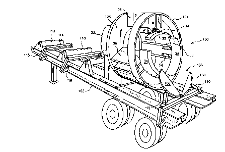
FIG. 5 is a perspective view of a trailer
mounted three-blade impact hammer delimber apparatus
provided in accordance with the principles of the
present invention; and
FIG. 6 is a schematic illustration of a
hydraulic circuit for an impact hammer delimber
apparatus of the invention.
Referring now more particularly to the
drawings, an impact hammer delimber apparatus, generally
indicated at 10, which embodies the principles of the
present invention is shown. The delimber apparatus
includes housing structure including a support assembly
having a base portion 12 which is constructed and
arranged to be trailer mounted, for example in a manner
shown in FIG. 5, or affixed to a tree harvester or
similar wheeled vehicle; and a support stand, generally
indicated at 14, mounted to the base portion 12 so as to
216032~
-
-4-
extend vertically therefrom. The support stand 14 of
the housing structure, includes opposing sidewalls 16, a
front wall 18 and a rear wall 20. The support assembly
further includes a generally cylindrical base tube 22
affixed to the support stand 14. The base tube 22
includes an axial opening 24 therethrough which is
adapted to receive stems of felled trees. A plate 26 of
the housing structure is mounted to the base tube 22 for
rotary motion with respect thereto and includes a bore
28 therethrough sized to mate generally with the opening
24 of the base tube 22. In the illustrated emhoA;ment,
the bore 28 is approximately 30 inches in diameter so as
to accept a 30 inch diameter tree stem.
Mounted to the front face of the plate 26 is
actuating structure, generally indicated at 32. In the
illustrated embodiment, the actuating structure includes
a pair of actuating assemblies 36 spaced 180 apart on
the plate 26. Each actuating assembly 36 is operatively
associated with a cutting blade or blade structure 34 to
move the cutting blade 34 into engagement with a tree.
As shown, each cutting blade 34 has a curved cutting
edge 38 preferably angled approximately 30 degrees with
respect to the horizontal, to facilitate delimbing.
With reference to FIG. 3, the apparatus 10
includes impact hammer structure comprising a plurality
of conventional impact hammers 40 such that each cutting
blade 34 is operatively coupled to an associated impact
hammer 40. The tool portion of the impact hammer 40 is
coupled to the cutting blade 34 such that successive
impacts of the impact hammer 40 on the cutting blade 34
move the cutting blade 34 progressively through a limb
of a tree, as will be apparent below. As noted above,
each impact hammer 40 may be of any conventional
construction having an impact class of approximately
3S 175/130 J/ft-lb. For example, Rammer Corporation Model
S-23, NKP Co. Model No. H-08X or INDEC0 Corp. Model No.
MES181 impact hammer could be used.
2160~2S
.
--5--
As noted above, each actuating assembly 36 is
operatively associated with an associated impact hammer
40 and cutting blade 34 so as to move the associated
cutting edge 38 into engagement with a limb. With
reference to FIGS. 1 and 3, each actuating assembly 36
includes a pair of stationary plates 42 mounted to the
plate 26. A hydraulic cylinder 44 is affixed at one end
thereof between the stationary plates 42 by pin 43. The
piston end of the hydraulic cylinder 44 is coupled to a
swing arm 46 at pin 47. One end of the swing arm 46 is
pivotally coupled between the stationary plates 42 via
pin 49 while a second end of the swing arm 46 is
pivotably coupled to a swing plated assembly 48 via pin
51. A second swing arm 50 is pivotably coupled between
the stationary plates 42 at one end thereof at pin 53
and pivotally coupled to the swing plate assembly 48 at
another end thereof via pin 55. The swing plate
assembly includes a pair of spaced swing plates 57. The
impact hammer structure 40, with cutting blade 34
attached, is fixedly mounted to the swing plate
assembly 48 between the pair of swing plates 57.
As shown in FIG. 3, the actuating assemblies 36
are disposed in position to accept a 30 inch diameter
tree within an opening 52 therebetween. In this
position, each cylinder 44 is retracted which in turn
retracts an associated swing arm assembly 48 to the
position shown. Upon actuating the cylinders 44, the
pistons extend, thereby rotating the associated swing
arm assembly 48 to a position shown in FIG. 4, whereby
the swing arm assemblies 48 are moved toward each other
thereby reducing the opening 52 to receive smaller trees
or to accommodate the reducing diameter of the tree stem
as the stem is moved through the apparatus from its
trunk portion to its distal end portion. In the
illustrated embodiment, the size of opening 52 is
adjustable between 4 and 30 inches.
As shown in FIG. 1, mounted on each swing arm
assembly 48 is support and feed structure in the form of
216032~
_
--6--
a drive wheel assembly 54. Each drive wheel assembly 54
includes two spaced toothed wheels 56, 58 mounted
between the swing plates 57. Each drive wheel assembly
54 is adjustable and moves with an associated swing arm
assembly 48 and is driven by a pair of conventional
hydraulic motors 60. The drive wheel assemblies 54
cooperate to support the tree stem during a delimbing
procedure and to move the tree stem through the
apparatus 10.
When only two cutting blades are provided, it
is preferable to rotate the plate 26 between 0 and 180
so that limbs about the entire periphery of the tree
stem may be delimbed. Thus, as shown in FIG. 2, a race
ring 62 is mounted to the peripheral portion of the base
tube 22 at a proximal portion thereof. The plate 26 is
rotatably supported on the race ring 62 via a plurality
of spaced bearings 64. The plate 26 includes a sprocket
member 66 having a plurality of sprocket segments 68.
To provide a structure for rotating the plate 26, a pair
of power cylinders 70 are provided, one disposed on each
side of the base plate 12. Each power cylinder 70
includes a chain support member 72 for supporting a
portion of a chain 74. As shown in FIG. 2, the chain 74
extends from each support member 72 and cooperates with
the sprocket segments 68 such that alternating up and
down movement of the cylinders 70 causes the plate 26 to
swing between 0 and 180. The power cylinders 70 are
coupled to the base plate via arm members 76. Note that
the power cylinders and arm members are not shown in
FIG. 1.
With reference to drawings, the operation of
the delimber apparatus 10 will be appreciated. A felled
tree is brought to the opening 52 by loader or the like
such that the large diameter trunk portion is inserted
first into the opening 52. The cylinders 44 are
actuated such that the cutting blade edges 38 are moved
into engagement with the tree stem. The tree is moved
in the direction of arrow A through the apparatus 10 by
2160325
-7-
the drive wheel assemblies 54. The impact hammer
structure 40 is in a neutral mode until resistance is
experienced. Thus, once the cutting blade 34 is in
contact with an associated limb of the tree, the
associated impact hammer 40 begins to fire into the limb
in response to pressure and resistance. To insure that
limbs are removed around the entire periphery of the
tree stem, the power cylinders 70 are actuated so as to
swing the plate 26 between 0 and 180, thereby swinging
the cutting blades 34 between 0 and 180 such that the
complete 360 periphery of the tree stem can be delimbed.
As the diameter of the tree stem becomes smaller near
the distal end thereof, the cylinders 44 operate to move
the swing plate assembly 48 toward each other (FIG. 4)
so as to maintain contact of the cutting blades 34 with
the tree stem. Positioning of the cutting blades is
therefore adjustable to accommodate 30 to 4 inch
diameter tree stems. When approximately a 4 inch
diameter portion of the tree has been reached, the waste
end of the tree is sheared-off by any conventional
method. FIG. 5 shows a conventional tree topper shear
blade assembly, generally indicated at 106, for
shearing-off the waste end of the tree which will be
explained below more fully. Since the diameter of the
tree waste portion is small, the forces required to
sever the waste portion by shearing are not significant.
FIG. 5 shows in another embodiment of the
impact hammer delimber apparatus provided in accordance
with the principles of the present invention. Common
parts are given the same numerals as in the previous
embodiment, and only the differences between the two
embodiments are discussed. As shown, the delimber
apparatus 100 is mounted on a wheeled trailer 102. The
delimber apparatus 100 includes three actuating
assemblies 36 and associated cutting blades 34 and
impact hammers 40. The cutting blades 34 are spaced
approximately 120 apart. The actuating assemblies,
cutting blades and impact hammers are identical to those
2160325
-8-
previously described. However, since the cutting blades
34 are arranged to ensure that the entire periphery of
the tree stem may be delimbed, there is no need to
rotate a rotary plate as in the apparatus 10. Thus,
plate 126 is fixed to the base tube 22. Further, the
power cylinders of FIG. 2 are not required. The
apparatus 100 includes a support ring 104 coupled to the
actuating assemblies 36 for increased support.
Mounted on the trailer 102 in front of the
apparatus 100 is a tree topper shear assembly, generally
indicated at 106. The assembly 106 includes two
opposing shear blades 108, each being controlled by an
associated hydraulic cylinder 110. Movement of the
cylinders 110 from the position shown closes the blades
108 to shear-off the wast portion of the tree. A
hydraulic positioning cylinder 112 is coupled to the
assembly 106 so as to adjust the height thereof to place
the assembly 106 a range of vertical positions.
At the rear of the trailer 102, a plurality of
tree trunk exit rails 114 are provided which receive the
delimbed stem as it exits the apparatus 100. Each exit
rail 114 is vertically adjustable via an associated
hydraulic cylinder 116 coupled thereto. A series of
rollers 118 are mounted on the trailer 102 adjacent the
exit rails 114 for ease in handling the delimbed stem.
Although not shown, it can appreciated that
four cutting blades can be mounted 45 apart so as to
cover the entire 360 periphery of a tree, without the
need to rotate a portion of the apparatus.
A hydraulic circuit for the apparatus 100
having three impact hammers 40 is shown in FIG. 6. A
control valve assembly, generally indicated at 80, is
provided to control the operation of the apparatus 100.
In the illustrated embodiment, the control valve
assembly 80 includes seven conventional control valves
82 for controlling the drive wheel assemblies 54, the
hydraulic cylinders 44 of the actuating assemblies 36,
the impact hammers 40, the tree trunk exit rails
2160325
cylinders 116, the tree topper shear cylinders 110, and
the tree topper shear assembly positioning cylinder 112.
A supply pump 90 supplies hydraulic fluid to the control
valves assembly 80. Hydraulic oil pressure is supplied
by engine 92. It can be appreciated that instead of
providing engine 92, the hydraulic oil and pressure may
be supplied by from the auxiliary hydraulics of a
vehicle (not shown).
The aforementioned impact cutting method works
well in hard wood trees and equally well in soft wood
trees. It can be appreciated that pneumatic, hydraulic
or electric, mech~n;cal inertial-type of energy may be
utilized to provide the impact force for the cutting
action.
It can be appreciated that the delimber
structure of the invention provides an easy and
effective way to delimb trees without the danger of
injury caused by manual chain sawing or the like.
Although the invention has been described with
reference to delimbing a felled tree, it is within the
contemplation of the invention to provide impact hammer
structure for debarking of logs. Conventional type
debarkers are either flail, ring, drum or rosser head
which are very costly to produce and maintain. The use
of impact hammers for debarking provides a cost
effective way of performing the debarking function.
It thus will be seen at the objects of this
invention had been fully and effectively accomplished.
It will be realized, however, that the foregoing
preferred embodiment of the present invention has been
shown and described for the purposes of illustrating the
structural and functional principles of the present
invention and are subject to change without the
departure form such principles. Therefore, this
invention includes all modifications encompassed within
the spirit of the following claims.