Language selection

Search

Patent 2160397 Summary

Third-party information liability

Some of the information on this Web page has been provided by external sources. The Government of Canada is not responsible for the accuracy, reliability or currency of the information supplied by external sources. Users wishing to rely upon this information should consult directly with the source of the information. Content provided by external sources is not subject to official languages, privacy and accessibility requirements.

Claims and Abstract availability

Any discrepancies in the text and image of the Claims and Abstract are due to differing posting times. Text of the Claims and Abstract are posted:

  • At the time the application is open to public inspection;
  • At the time of issue of the patent (grant).
(12) Patent Application: (11) CA 2160397
(54) English Title: PART HOLDING PRESS TOOL WITH NON-MAGNETIC PART HOLDING MECHANISM
(54) French Title: MACHINE-OUTIL PORTE-PIECE AVEC MECANISME PORTE-PIECE AMAGNETIQUE
Status: Deemed Abandoned and Beyond the Period of Reinstatement - Pending Response to Notice of Disregarded Communication
Bibliographic Data
(51) International Patent Classification (IPC):
  • B23Q 3/00 (2006.01)
  • B25B 5/14 (2006.01)
  • B25B 27/06 (2006.01)
(72) Inventors :
  • MEYER, HERBERT J., JR. (United States of America)
(73) Owners :
  • UNOVA IP CORP.
(71) Applicants :
  • UNOVA IP CORP. (United States of America)
(74) Agent: MARKS & CLERK
(74) Associate agent:
(45) Issued:
(22) Filed Date: 1995-10-12
(41) Open to Public Inspection: 1996-05-08
Availability of licence: N/A
Dedicated to the Public: N/A
(25) Language of filing: English

Patent Cooperation Treaty (PCT): No

(30) Application Priority Data:
Application No. Country/Territory Date
08/335,497 (United States of America) 1994-11-07

Abstracts

English Abstract


A workpiece holding press tool with an elongated body
having an annular collar extending from an end face and a plug
member secured to the collar by a fastener. The plug forms an
annular groove with the body that receives a retainer clip which
frictionally engages the inside surface of a workpiece to retain
the workpiece on the press tool. The retainer clip is a circular
spring steel wire having opposed ends with a relieved portion
formed on the outside surface thereof to prevent scratching,
marring or otherwise damaging the inside surface of the
workpiece. In another embodiment, a second plug is added to
provide a second annular groove to receive a second retainer
clip for holding elongated workpieces having a cylindrical
inside diameter.


Claims

Note: Claims are shown in the official language in which they were submitted.

CLAIMS:
1.
A workpiece holding press tool for pressing a workpiece
into a bore of a body, comprising:
a press member having an end face,
a plug having a body with an annular side wall, an
end wall and a circumferentially continuous shoulder opening
radially outwardly of said side wall and axially outwardly of
said end wall to define in cooperation with said end face of
said press member a groove for receiving a clip,
a fastener releasably securing said plug on said press
member, and
a split circular retainer clip of a resilient metal
having opposed ends with a relieved outer surface thereon and
received in said groove to frictionally hold and retain a
workpiece on said press member.
-8-

2.
A workpiece holding press tool for pressing a workpiece
into a bore of a body, comprising:
an elongated press member having an end face,
a first plug having a body with an annular side wall,
an end wall and a circumferentially continuous shoulder opening
radially outwardly of said side wall and axially outwardly of
said end wall to define in cooperation with said end face of
said press member a first groove for receiving a clip,
a second plug having a body with an annular side wall,
an end wall and a circumferentially continuous shoulder opening
radially outwardly of said side wall and axially outwardly of
said end wall to define in cooperation with said first plug a
second groove for receiving a clip,
a fastener releasably securing said first and second
plugs on said press member, and
first and second split circular retainer clips of a
resilient metal having opposed ends with a relieved outer surface
thereon and received in said first and second grooves to
frictionally hold and retain a workpiece on said press member.
-9-

3.
A workpiece holding press tool for pressing a workpiece
into a bore of a body, comprising:
an elongate press member having an end face and an
annular collar extending from said end face, said press member
having a central threaded opening and a counterbore through
said collar,
a plug having an annular body located within said
counterbore and secured to said press member, said plug having
a head portion extending outside of said counterbore and forming
a groove with said collar, and
a split circular retainer clip having opposed ends
with a relieved outer surface thereon located in said groove
to frictionally hold and retain a workpiece.
4.
The press tool of claim 3 wherein the head of said
plug has a stepped down neck that abuts said collar to form
said groove.
- 10 -

5.
The press tool of claim 3 wherein said plug has a
through opening and a counterbore, and
a threaded fastener extending through the opening and
threaded into the opening in said press member to secure said
plug to said press member.
6.
The press tool of claim 3 wherein said workpiece is
hollow and abuts the end face of said press member and wherein
the retainer clip frictionally engages the inside diameter of
the workpiece to hold it on said press member.
7.
The press tool of claim 6 wherein said workpiece has
a tapered inside diameter.
8.
The press tool of claim 3 wherein said workpiece is
hollow with a surface engaged by said retainer clip which surface
has an inside diameter less than the outside diameter of said
clip in its free state and the base of said groove has a diameter
less than the inside diameter of said clip when engaged with
said surface of said workpiece.
-11-

9.
The press tool of claim 3 wherein said relieved
surfaces of said retainer clip are substantially flat.
10.
A workpiece holding press tool for pressing a workpiece
into a bore of a body, comprising
an elongate press member having an end face and an
annular collar extending from the end face, said press member
having a central threaded opening and a counterbore through
said collar,
a spacer plug having an annular body located within
said counterbore and a head portion extending outside of said
counterbore, and forming a first groove with said press member,
said head portion having an end face, said spacer plug having
a counterbored through opening therethrough,
a plug member having an annular body located within
the counterbore in said spacer plug, a head portion extending
outside of the counterbore in said spacer plug and forming a
second groove with said spacer plug, and a counterbored opening
extending therethrough, and
first and second split circular retainer clips having
opposed ends with a relieved outer surface thereon and received
in said first and second grooves to frictionally hold and retain
a workpiece on said press member.
-12-

11.
The press tool of claim 10 wherein said spacer plug
has a stepped-down neck head portion which abuts said collar
of said press member to form said first groove, and said plug
member has a stepped-down neck on its head portion which abuts
the end face of said spacer plug to form said second groove.
12.
The press tool of claim 11 which alo comprises a
threaded fastener extending through the openings in said spacer
plug and said plug member and threaded into the threaded opening
of said press member to secure said spacer plug and said plug
member to said press member.
13.
The press tool of claim 10 wherein said workpiece is
hollow and abuts the end face of said press member and wherein
said retainer clips frictionally engage the inside diameter of
the workpiece to hold it thereon.
-13-

14.
The press tool of claim 13 wherein said workpiece has
a straight inside diameter.
15.
The press tool of claim 14 wherein both retainer clips
frictionally engage the inside diameter of said workpiece.
-14-

Description

Note: Descriptions are shown in the official language in which they were submitted.


2160397
WHG:JLW:sal t362
PART HOLDING PRESS TOOL WITH
NON-MAGNETIC PART HOLDING MECHANISM
Field of the Invention
This invention relates to workpiece holders and more
particularly to a non-magnetic holder for a hollow workpiece
on the inside diameter thereof.
Background of the Invention
Various forms of workholders have been in use for
holding hollow workpieces. For example, permanent magnets
embedded in a press tool as well as electromagnets within a
press tool have been used to hold metallic workpieces. However,
the use of magnets inherently attracts metal chips, metal
shavings and other fine metal particles to the press tool. This
affects the press tool's ability to properly and accurately
locate and press a workpiece. This can al~o adversely affect
the ability of the press tool to properly hold a workpiece to
press it into position. Other types of workpiece holders include
spring loaded fingers built into the nose of the press tool.
The main drawback to this type of workpiece holder is that it
limits the size of the workpiece to be held because space is
needed for the spring fingers, springs, pivots and other various
pieces of assembly. Split collet type tools have also been used
to hold a hollow workpiece being pressed to prevent it from

2160397
falling off the end of the tool. The main disadvantage to the
split collet type of tool is that it is fragile because the
inside diameter of the collet has to be thin enough to flex and
yet be made of hardened steel for wear.
Summary of the Invention
A workpiece holder press tool is provided for holding
a hollow workpiece having either a tapered or straight inside
diameter. The workpiece holder comprises an elongated pressing
tool which has a separable nose portion or plug that carries a
circular retainer clip for frictionally retaining the inside
of the workpiece. The separable plug provides easy assembly
withoutpermanentdistortionofthe retainer clip. Additionally,
the clip comprises a resilient split circular spring wire having
opposed ends. The ends have a flattened outer surface to
eliminate sharp corners and edges to prevent damaging the inside
surface of the workpiece and facilitate compression of the clip.
In another embodiment, a spacer plug is added to increase the
length of the entry nose for an additional clip to hold an
elongated workpiece.
Objects, features and advantages of this invention
are to provide a workpiece holding press tool that can hold a
workpiece in position without the use of magnets, can hold
workpieces of varying composition, allows for variations in
tolerance of the location that the part is being pressed into,

216~397
allows the retainer clip to be installed or changed without
distortion or stretching, is simple, stable, rugged, durable,
reliable, quick and easy to use and assemble and of relatively
simple design and economical manufacture.
Brief De~cription of the Drawing~
These and other objects, features and advantages of
this invention will be apparent from the following detailed
description, appended claims and accompanying drawings inwhich:
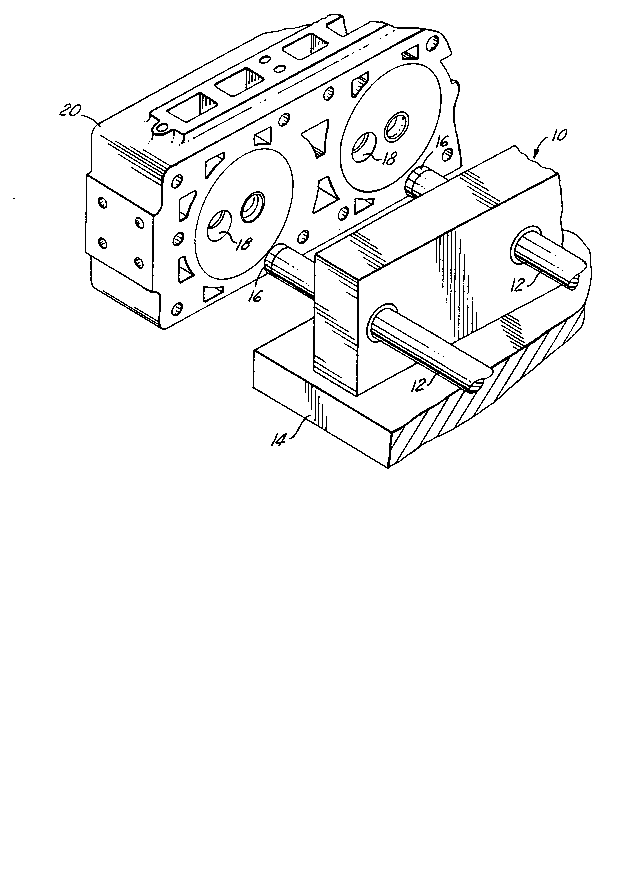
FIG. 1 is a perspective view of a workpiece holding
press tool and an engine cylinder head;
FIG. 2 is an enlarged sectional view of the press
tool for holding a workpiece with an inclined internal diameter;
FIG. 3 is an enlarged end view of the circular clip;
FIG. 4 is an enlarged side view of the opposed ends
of the clip; and
FIG. 5 is an enlarged sectional view of a modified
press tool for holding a straight internal diameter workpiece.

21 6D397
Detailed Description
Referring in more detail to the drawings, FIG. 1
illustrates a press 10 with a plurality of press tools 12
reciprocally mounted in a base support 14. Each press tool 12
holds a hollow workpiece 16, such as a valve seat, cup plug or
bushing. The press tools 12 are reciprocated by a drive (not
shown) to press with an interference fit each workpiece 16 into
a bore 18 of a body 20 such as a cylinder head for an internal
combustion engine.
The press tool 12 (FIG. 2) is designed to hold a
workpiece having a tapered or frusto-conical inside surface 24.
The press tool 12 has an elongated body made preferably from
hardened steel with an end face 26 from which a collar 28 axially
extends. The body of the press tool has a threaded bore 30 with
a counterbore 32 that receives an annular plug 34. The plug
is secured to the press tool by a threaded fastener or cap screw
36 extending through a counterbored opening 38 in the plug and
threaded into the bore 30 in the press tool. The plug has a
head portion 40 with a necked-down shoulder 41 which abuts the
collar 28 to form an annular groove 42.
A retainer clip 44 is received in the groove 42. The
clip 44 comprises a resilient metal split ring (FIG. 3) with
opposed ends 46 and preferably is made from wire such as spring
steel wire or tempered music wire. The outer surface of the
opposed ends 46 are ground or otherwise relieved preferably by

21603g7
flats48 todecrease their thickness and eliminate sharp corners.
This prevents the inside surface 24 of the workpiece 22 from
being scraped, scratched or otherwise marred by the clip 44 and
permits the ring to be smoothly compressed radially inwardly
to frictionally retain the workpiece. In its unstressed state,
the maximum outside diameter of the clip 44 is greater than the
diameter of the surface 24 of the workpiece 16 which it engages.
Once the clip 44 is installed on the tool 12, the
workpiece 16 is slipped over the plug 34 so that it engages the
end face 26. The clip 44 engages the inside surface 24 of the
workpiece 16 which tapers inwardly away from the axis of the
press tool 12. The frictional forces between the workpiece 16
and the clip 44 increase as the workpiece 16 is advanced onto
the press tool 12 (due to radially inward compression of the
clip) so that the workpiece 16 is frictionally held onto the
press tool 12 by the clip 44. To permit the clip 44 to be
radially compressed, the shoulder 41 has a sufficiently smaller
diameter than the inside diameter of the clip in its free or
uncompressed state.
FIG. 5 illustrates another embodiment for holding a
workpiece 50, such as an elongated bushing, having a straight
cylindrical inside surface 52. To increase the length of the
press tool and thus its ability to hold the workpiece 50, a
spacer plug 54 is provided between the press tool 12 and the
plug 34. The spacer plug 54 has an annular portion 56 that is

2160397
received in the counterbore 32 in the press tool 12. The spacer
plug 54 extends outside of the counterbore 32 and has a through
opening 58 with a counterbore 60. The plug 34 is received in
the counterbore 60 and both the plug 34 and spacer plug 54 are
secured to the press tool by a threaded fastener or cap screw
62 received in and extending through the openings 38 and 58 in
the plugs, and threaded into the opening 30 in the press tool.
The spacer plug 54 has a necked-down shoulder 64 that
abuts the collar 28 of the press tool to form a groove 66 in which
a clip 44 is received. The plug 34is received in the counterbore
60 of the spacer plug 54 and bears on its end face 68 so that
the necked-down shoulder 41 forms a second groove 70 that
receives a second clip 44.
When the clips 44 are received in the first and second
grooves 66 and 70, the workpiece 50 is inserted over the end of
the press tool 12 to abut the end face 26 and so that the clips
44 are compressed radially inward and frictionally engage the
inside surface 52 of the workpiece 50. The frictional forces
between the surface 52 and the clips 44 are great enough to
securely retain the workpiece 50 on the press tool 12.
The removable feature of the plugs 34 and 54 allow
the clips 44 to be installed without stretching, bending or
permanent deformation because the necked-down shoulders 41 and
64 have a smaller inside diameter than the clips 44 in their
freeoruncompressed state. The clips 44 are simply inserted over

21S0397
the necked-down shoulders 41 and 64 of the plugs 34 and 54 and
then the plugs are assembled on and secured to the tools 12 by
the cap screws 36 or 62.
In use, the workpiece 16 or 50 is inserted onto the
end of the press tool 12 so that the clips 44 are compressed
radially inward and frictionally grip the inside surface 24 or
52 thereof. The press tools 12 are then reciprocated by the
drive mechanism of the press 10 so that the workpiece 16 or 50
is pressed into the bore 18 of the body 20. As the press tool 12
is withdrawn, the frictional forces between the bore 18 and the
workpiece 16 or 50 are sufficiently greater than the friction
forces between the workpiece 16 & 50 and the clips 44 so that
the clips 44 become disengaged or released from the workpiece
16 or 50.

Representative Drawing
A single figure which represents the drawing illustrating the invention.
Administrative Status

2024-08-01:As part of the Next Generation Patents (NGP) transition, the Canadian Patents Database (CPD) now contains a more detailed Event History, which replicates the Event Log of our new back-office solution.

Please note that "Inactive:" events refers to events no longer in use in our new back-office solution.

For a clearer understanding of the status of the application/patent presented on this page, the site Disclaimer , as well as the definitions for Patent , Event History , Maintenance Fee  and Payment History  should be consulted.

Event History

Description Date
Inactive: IPC from MCD 2006-03-12
Application Not Reinstated by Deadline 2003-10-14
Time Limit for Reversal Expired 2003-10-14
Inactive: Status info is complete as of Log entry date 2002-12-30
Inactive: Abandon-RFE+Late fee unpaid-Correspondence sent 2002-10-15
Deemed Abandoned - Failure to Respond to Maintenance Fee Notice 2002-10-15
Inactive: Multiple transfers 2000-03-02
Letter Sent 1999-10-06
Inactive: Multiple transfers 1999-08-27
Application Published (Open to Public Inspection) 1996-05-08

Abandonment History

Abandonment Date Reason Reinstatement Date
2002-10-15

Maintenance Fee

The last payment was received on 2001-09-28

Note : If the full payment has not been received on or before the date indicated, a further fee may be required which may be one of the following

  • the reinstatement fee;
  • the late payment fee; or
  • additional fee to reverse deemed expiry.

Please refer to the CIPO Patent Fees web page to see all current fee amounts.

Fee History

Fee Type Anniversary Year Due Date Paid Date
MF (application, 2nd anniv.) - standard 02 1997-10-14 1997-10-01
MF (application, 3rd anniv.) - standard 03 1998-10-13 1998-10-05
Registration of a document 1999-08-27
MF (application, 4th anniv.) - standard 04 1999-10-12 1999-10-05
MF (application, 5th anniv.) - standard 05 2000-10-12 2000-10-03
MF (application, 6th anniv.) - standard 06 2001-10-12 2001-09-28
Owners on Record

Note: Records showing the ownership history in alphabetical order.

Current Owners on Record
UNOVA IP CORP.
Past Owners on Record
HERBERT J., JR. MEYER
Past Owners that do not appear in the "Owners on Record" listing will appear in other documentation within the application.
Documents

To view selected files, please enter reCAPTCHA code :


To view images, click a link in the Document Description column. To download the documents, select one or more checkboxes in the first column and then click the "Download Selected in PDF format (Zip Archive)" or the "Download Selected as Single PDF" button.

List of published and non-published patent-specific documents on the CPD .

If you have any difficulty accessing content, you can call the Client Service Centre at 1-866-997-1936 or send them an e-mail at CIPO Client Service Centre.


Document
Description 
Date
(yyyy-mm-dd) 
Number of pages   Size of Image (KB) 
Representative drawing 1998-03-11 1 29
Cover Page 1996-07-02 1 16
Abstract 1996-05-08 1 22
Description 1996-05-08 7 221
Drawings 1996-05-08 2 71
Claims 1996-05-08 7 146
Reminder of maintenance fee due 1997-06-12 1 109
Reminder - Request for Examination 2002-06-13 1 118
Courtesy - Abandonment Letter (Maintenance Fee) 2002-11-12 1 179
Courtesy - Abandonment Letter (Request for Examination) 2002-12-24 1 167