Language selection

Search

Patent 2160405 Summary

Third-party information liability

Some of the information on this Web page has been provided by external sources. The Government of Canada is not responsible for the accuracy, reliability or currency of the information supplied by external sources. Users wishing to rely upon this information should consult directly with the source of the information. Content provided by external sources is not subject to official languages, privacy and accessibility requirements.

Claims and Abstract availability

Any discrepancies in the text and image of the Claims and Abstract are due to differing posting times. Text of the Claims and Abstract are posted:

  • At the time the application is open to public inspection;
  • At the time of issue of the patent (grant).
(12) Patent: (11) CA 2160405
(54) English Title: A WALL SUPPORT ASSEMBLY
(54) French Title: SUPPORT MURAL
Status: Expired and beyond the Period of Reversal
Bibliographic Data
(51) International Patent Classification (IPC):
  • A47B 96/06 (2006.01)
  • A47B 57/30 (2006.01)
  • A47B 96/00 (2006.01)
  • B01L 9/02 (2006.01)
(72) Inventors :
  • BASTIAN, JOHN M. (United States of America)
(73) Owners :
  • FISHER HAMILTON SCIENTIFIC INC.
(71) Applicants :
  • FISHER HAMILTON SCIENTIFIC INC. (United States of America)
(74) Agent: BORDEN LADNER GERVAIS LLP
(74) Associate agent:
(45) Issued: 2005-05-10
(22) Filed Date: 1995-10-12
(41) Open to Public Inspection: 1996-04-14
Examination requested: 2001-10-24
Availability of licence: N/A
Dedicated to the Public: N/A
(25) Language of filing: English

Patent Cooperation Treaty (PCT): No

(30) Application Priority Data:
Application No. Country/Territory Date
324,002 (United States of America) 1994-10-13

Abstracts

English Abstract


A wall support assembly includes a pair of horizontal
members and one or more vertical members. One may secure the
horizontal members to a wall member a predetermined distance
apart. Each of the horizontal members defines a recess or pocket
which lies longitudinally of the member for releasably receiving
a distal end portion of a vertical member. The vertical members
define openings from which one may hang storage members or
similar components.


Claims

Note: Claims are shown in the official language in which they were submitted.

CLAIMS:
1. A wall support assembly, comprising:
a first, elongate member securable to a wall member;
a second, elongate member securable to the wall member
a predetermined distance away from said first member;
a third, elongate member for extending between said
first and second members;
each of said first and second members defining a
recess disposed longitudinally of the member for releasably
receiving a distal end portion of said third member;
each of the first and second members defining at least
one transverse slot and one transverse end portion;
the third member defining a pocket and at least one
leg portion;
the slots of the first and second members receiving
the leg portion of the third member;
the pocket of the third member receiving the end
portions of the first and second members; and
distal ends of the third member extending into the
recess of the first and second members in loose, sliding
engagement.
2. The assembly of claim 1, further comprising means for
securing the first and second members to the wall member.
3. The assembly of claim 1 or 2, wherein the recess
defined by each of the first and second members extends
along the entire length of the first or second member.
4. The assembly of claim 1, 2 or 3, wherein the first and
second members are adapted to lie in spaced, parallel
relation to each other.
5. The assembly of claim 4, wherein the third member is
adapted to lie perpendicularly to the first and second
members.
6

6. The assembly of any one of claims 1 to 5, wherein the
first and second members have a generally channel-like
cross-section.
7. The assembly of claim 6, wherein the third member has
a generally channel-like cross-section.
8. The assembly of any one of claims 1 to 7, further
comprising a fourth member, the recess defined by the first
and second members receiving a distal end portion of the
fourth member.
9. The assembly of any one of claims 1 to 8, wherein the
first, second and third members are one-piece integrally
formed components.
10. A wall support assembly, comprising:
first and second elongate, horizontal members, said
first and second horizontal members being secured to a wall
member generally parallel to each other and a predetermined
distance apart;
a plurality of elongate, vertical members disposed
generally perpendicularly to the horizontal members between
the horizontal members;
each of said horizontal members defining a recess
disposed longitudinally of the horizontal member for
releasably receiving a distal end portion of each of the
vertical members;
the distal ends of vertical members extending into the
recesses or the first and second members in loose, sliding
engagement;
each of the first and second members defining at least
one transverse slot and one transverse end portion;
the vertical members defining a pocket and at least
one leg portion;
the slots of the first and second members receiving
the leg portion of the vertical members; and
7

the pocket of the vertical members receiving the end
portions of the first and second members.
11. The assembly of claim 10, wherein each vertical member
defines a plurality of openings for receiving a hook of a
storage member or the like, said openings being spaced from
each other and disposed longitudinally of the vertical
member.
12. The assembly of claim 10 or 11, wherein the first,
second and vertical members are one-piece integrally formed
components.
8

Description

Note: Descriptions are shown in the official language in which they were submitted.


_2160405
A WALL SUPPORT ASSEMBLY
BACKGROUND OF THE INVENTION
Field Of The Invention
The present invention relates to a support assembly
used to mount various components to a wall, and more particularly
to a support assembly with horizontal and vertical rails that
provide a low profile structure for mounting storage enclosures
and similar structures to a wall. The present invention finds
particular utility for mounting laboratory components, but it may
serve as a wall mount in a wide variety of other applications.
Description Of The Prior Art
The prior art includes a wide variety of wall mounting
structures. Some of these structures do not provide the load
capacity required for applications such as mounting laboratory
enclosures or furniture to the walls of the laboratory. Those
that do provide adequate load capacity are massive structures or
complex devices which do not allow quick and easy installation.
The wall support assembly of the present invention
avoids the disadvantages of the prior art wall mounting
structures. It provides a low profile rail system which mounts
directly to a wall. It allows quick and easy assembly and
installation. It is a simple structure which minimizes the cost
of fabrication and installation.
SUMMARY OF THE INVENTION
In accordance with one embodiment of the present
invention, a wall support assembly includes a first and second
elongate member which are securable to a wall member a
predetermined distance apart from each other. At least one other
elongate member lies disposed between the first and second
1

21so4o
members. Each of the first and second members defines a recess
or pocket for releasably receiving a distal end portion of the
other member.
BRIEF DESCRIPTION OF THE DRAWINGS
For a more complete understanding of this invention one
should now refer to the embodiment illustrated in greater detail
in the accompanying drawings and described below by way of an
example of the invention. In the drawings:
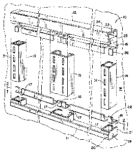
FIG. 1 is a perspective view of the wall support
assembly of the present invention;
FIG. 2 is a sectional view taken along line 2-2 in FIG.
1;
FIGS. 3 and 4 are side elevational view which
illustrate the method of securing a vertical member between two
horizontal members;
FIG. 5 is a perspective view of a wall support assembly
of the present invention mounted above a cabinet which lies
disposed against a wall which supports the assembly: and
FIG. 6 is a perspective view of the wall support
assembly of the present invention mounted to a wall and
supporting a shelf assembly.
While the following disclosure describes the invention
in connection with one embodiment one should understand that the
invention is not limited to this embodiment. Furthermore, one
should understand that the drawings are not to scale and that
graphic symbols, diagrammatic representatives, and fragmentary
views, in part, illustrate tie embodiment. In certain instances,
the disclosure may not include details which are not necessary
for an understanding of the present invention such as
conventional details of fabrication and assembly.
DETAILED DESCRIPTION OF
THE DRAWINGS AND AN EMBODIMENT
Turning now to the drawings, FIG. 1 shows the wall
2

~16040~
support system of the present invention at 10. The system
generally includes a first horizontal member il, a second
horizontal member 12, a first vertical end member 13, a second
vertical end member 14, and at least one member 15 which lies
between the vertical end members 13 and 14. The horizontal
members lie fixedly secured to a wall W; and they receive distal
end portions of the vertical members as described below.
The assembly 10 shown in FIG. 1 includes one
intermediate member 15. However, the assembly may include two or
more intermediate members 15, or it may not include any
intermediate members at all. Furthermore, the assembly 10 may
include only one or more end members or only one or more
intermediate members depending on the loading requirements of the
application of the present invention.
The members ll-15 are elongate members made out of
metal, plastic or any other material of high strength and
rigidity. The horizontal members 11 and 12 have a channel-like
cross-sectional configuration (See FIGS. 1, 2 and 4). Each one
defines a recess or pocket 16 which extends along its entire
length and receives distal ends of the vertical members 13-15.
Each of the members 11 and 12 also defines slots 17 and 18
disposed at predetermined spacing along the length of the member.
Those slots receive edge portions of the vertical members as
shown in FIG. 2.
The bottom horizontal member 11 includes a bottom
portion 19 and two leg portions 20 and 21. The leg portion 21
extends outwardly of the bottom portion 19, a greater distance
than does the leg portion 20. This leg portion 21 includes a
generally S-shaped end portion 22 which defines the slots 17 and
18.
Similarly, the top horizontal member 12 includes a top
portion 23 and two leg portions 24 and 25. The leg portion 25
extends outwardly of the top portion 23, a greater distance than
does the leg portion 24. This leg portion 24 includes a
generally S-shaped end portion 26 which defines slots 17 and 18.
3

216040
The cross-sectional configuration of the members 11 and 12 and
the position of one of the members 11 and 12 with respect to the
other allow the insertion of the distal ends of the vertical
members 13-15 as shown in FIGS. 3 and 4.
The vertical members 13-15 also have generally channel-
like cross-sectional configurations. Each one of the end members
13 and 14 includes a bottom portion 27, a straight leg portion
28, and an L-shaped leg portion 29. (The leg portions 28 and 29
may be straight or L-shaped. The L-shape provides additional
strength.) The leg portion 28 extends into a recess 30 in the
members 11 and 12: and the leg portion 29 extends into a slot 17.
In addition, each of the end members 13 and 14 defines a
plurality of openings 31 disposed in end to end relation a
predetermined distance apart along the entire length of the
member. Hook members (not shown) extend into these openings 31
to hang the various components from the system.
The vertical member 15 includes a bottom portion 32 and
two L-shaped leg portions 33 and 34 which extend into the slots
17 (See FIG. 2). (The slot 18 disposed between the slots 17,
which receive the leg portions 33, allows the insertion of an end
member in the position occupied by the intermediate member 15.)
This member is wider than the end members 13 and 14 to
accommodate two columns of openings 35 and 36. The two columns
of openings 35 and 36 allow a user to hang components in side by
side relation. In other words, the intermediate member 15
typically support the ends of two adjacent components.
Conventional screws or other similar devices (not
shown) secure the horizontal members 11 and 12 to the wall member
W. Similarly, one may use such securing means to secure the
vertical members 13-15 to the wall after placing the distal ends
of the vertical members in the pockets defined by the horizontal
members 11 and 12. Securing the vertical members 13-15 in this
manner provides a more secure installation.
FIGS. 3 and 4 show the method of installing the
vertical members 13-15 to the horizontal members 11 and 12. As
4

2160405
shown, the first step comprises inserting a distal end of a
vertical member into the pocket of the first horizontal member 11
or the second horizontal member 12. The next step comprises
inserting the opposite distal end in the pocket of the opposite
horizontal member.
The assembly 10 mounts various components, such as
storage units, shelves S or similar components to a wall (See
FIGS. 5 and 6). These components hang from hooks which extend
into the openings defined by the vertical members 13-15. In
addition, the vertical members 13-14 may support panels (era.,
steel, fabric, etc.) inserted between the vertical members to
provide decorative or sound absorbing wall covering or tackable
surfaces. The assembly provides a low profile rail system which
mounts directly to the wall. This assembly allows quick and easy
installation to the wall.
While the above description and the drawings disclose
and illustrate one embodiment, one should understand, of course,
that the invention is not limited to this embodiment. Those
skilled in the art to which the invention pertains may make
modifications and other embodiments employing the principles of
this invention, particularly upon considering the foregoing
teachings. Therefore, by the appended claims, the applicant
intends to cover any modifications and other embodiments as
incorporate those features which constitute the essential
features of this invention.

Representative Drawing
A single figure which represents the drawing illustrating the invention.
Administrative Status

2024-08-01:As part of the Next Generation Patents (NGP) transition, the Canadian Patents Database (CPD) now contains a more detailed Event History, which replicates the Event Log of our new back-office solution.

Please note that "Inactive:" events refers to events no longer in use in our new back-office solution.

For a clearer understanding of the status of the application/patent presented on this page, the site Disclaimer , as well as the definitions for Patent , Event History , Maintenance Fee  and Payment History  should be consulted.

Event History

Description Date
Time Limit for Reversal Expired 2009-10-13
Letter Sent 2008-10-14
Inactive: IPC from MCD 2006-03-12
Inactive: Late MF processed 2006-01-26
Letter Sent 2005-10-12
Grant by Issuance 2005-05-10
Inactive: Cover page published 2005-05-09
Pre-grant 2005-02-28
Inactive: Final fee received 2005-02-28
Letter Sent 2004-09-28
Notice of Allowance is Issued 2004-09-28
Inactive: Approved for allowance (AFA) 2004-09-17
Amendment Received - Voluntary Amendment 2002-02-13
Letter Sent 2001-11-21
Inactive: Status info is complete as of Log entry date 2001-11-21
Inactive: Application prosecuted on TS as of Log entry date 2001-11-21
Amendment Received - Voluntary Amendment 2001-11-06
All Requirements for Examination Determined Compliant 2001-10-24
Request for Examination Requirements Determined Compliant 2001-10-24
Application Published (Open to Public Inspection) 1996-04-14

Abandonment History

There is no abandonment history.

Maintenance Fee

The last payment was received on 2004-10-07

Note : If the full payment has not been received on or before the date indicated, a further fee may be required which may be one of the following

  • the reinstatement fee;
  • the late payment fee; or
  • additional fee to reverse deemed expiry.

Please refer to the CIPO Patent Fees web page to see all current fee amounts.

Fee History

Fee Type Anniversary Year Due Date Paid Date
MF (application, 2nd anniv.) - standard 02 1997-10-14 1997-09-04
MF (application, 3rd anniv.) - standard 03 1998-10-13 1998-09-02
MF (application, 4th anniv.) - standard 04 1999-10-12 1999-09-16
MF (application, 5th anniv.) - standard 05 2000-10-12 2000-09-20
MF (application, 6th anniv.) - standard 06 2001-10-12 2001-10-12
Request for examination - standard 2001-10-24
MF (application, 7th anniv.) - standard 07 2002-10-14 2002-09-25
MF (application, 8th anniv.) - standard 08 2003-10-13 2003-09-04
MF (application, 9th anniv.) - standard 09 2004-10-12 2004-10-07
Final fee - standard 2005-02-28
Reversal of deemed expiry 2005-10-12 2006-01-26
MF (patent, 10th anniv.) - standard 2005-10-12 2006-01-26
MF (patent, 11th anniv.) - standard 2006-10-12 2006-09-18
MF (patent, 12th anniv.) - standard 2007-10-12 2007-09-20
Owners on Record

Note: Records showing the ownership history in alphabetical order.

Current Owners on Record
FISHER HAMILTON SCIENTIFIC INC.
Past Owners on Record
JOHN M. BASTIAN
Past Owners that do not appear in the "Owners on Record" listing will appear in other documentation within the application.
Documents

To view selected files, please enter reCAPTCHA code :


To view images, click a link in the Document Description column. To download the documents, select one or more checkboxes in the first column and then click the "Download Selected in PDF format (Zip Archive)" or the "Download Selected as Single PDF" button.

List of published and non-published patent-specific documents on the CPD .

If you have any difficulty accessing content, you can call the Client Service Centre at 1-866-997-1936 or send them an e-mail at CIPO Client Service Centre.


Document
Description 
Date
(yyyy-mm-dd) 
Number of pages   Size of Image (KB) 
Representative drawing 1997-12-19 1 40
Cover Page 1996-07-29 1 15
Description 1996-04-14 5 225
Claims 1996-04-14 2 84
Drawings 1996-04-14 3 102
Claims 2002-02-13 3 94
Representative drawing 2004-09-24 1 22
Abstract 1996-04-14 1 14
Cover Page 2005-04-12 1 46
Reminder of maintenance fee due 1997-06-12 1 109
Acknowledgement of Request for Examination 2001-11-21 1 179
Commissioner's Notice - Application Found Allowable 2004-09-28 1 160
Maintenance Fee Notice 2005-12-07 1 172
Late Payment Acknowledgement 2006-02-09 1 165
Maintenance Fee Notice 2008-11-25 1 172
Fees 2004-10-07 1 17
Correspondence 2005-02-28 1 24