Language selection

Search

Patent 2160407 Summary

Third-party information liability

Some of the information on this Web page has been provided by external sources. The Government of Canada is not responsible for the accuracy, reliability or currency of the information supplied by external sources. Users wishing to rely upon this information should consult directly with the source of the information. Content provided by external sources is not subject to official languages, privacy and accessibility requirements.

Claims and Abstract availability

Any discrepancies in the text and image of the Claims and Abstract are due to differing posting times. Text of the Claims and Abstract are posted:

  • At the time the application is open to public inspection;
  • At the time of issue of the patent (grant).
(12) Patent Application: (11) CA 2160407
(54) English Title: STENT WHICH CAN BE IMPLANTED INTO A BODY VESSEL
(54) French Title: DRAIN POUVANT ETRE IMPLANTE DANS UN VAISSEAU
Status: Deemed Abandoned and Beyond the Period of Reinstatement - Pending Response to Notice of Disregarded Communication
Bibliographic Data
(51) International Patent Classification (IPC):
  • A61F 2/82 (2013.01)
  • A61B 5/026 (2006.01)
(72) Inventors :
  • GLASTRA, HENDRIK
(73) Owners :
  • CORDIS EUROPA N.V.
(71) Applicants :
  • CORDIS EUROPA N.V.
(74) Agent: MARKS & CLERK
(74) Associate agent:
(45) Issued:
(22) Filed Date: 1995-10-12
(41) Open to Public Inspection: 1996-04-14
Availability of licence: N/A
Dedicated to the Public: N/A
(25) Language of filing: English

Patent Cooperation Treaty (PCT): No

(30) Application Priority Data:
Application No. Country/Territory Date
9401690 (Netherlands (Kingdom of the)) 1994-10-13

Abstracts

English Abstract


The invention relates to a stent which can be
implanted into a body vessel characterised in that it
carries a detector for one or more body or environmental
parameters. The stent comprises a storage or registration
element for data provided by the detector as well as a
transmission circuit for emitting electromagnetic
radiation carrying information as regards the detected
parameter.


Claims

Note: Claims are shown in the official language in which they were submitted.

CLAIMS
1. Stent which can be implanted into a body
vessel characterised in that it carries a detector for
one or more body or environmental parameters.
2. Stent as claimed in claim 1, characterised
in that it comprises a storage or registration element
for data provided by the detector.
3. Stent as claimed in claim 1, characterised
in that the detector is a radiation detector.
4. Stent as claimed in claim 1, characterised
in that the detector is a liquid flow detector.
5. Stent as claimed in claim 1, characterised
in that the detector has been designed to detect the
concentration of one of the blood components.
6. Stent as claimed in claim 1, characterised
in that it comprises a radiation dosimeter.
7. Stent as claimed in claim 1, characterised
in that the stent comprises a transmission circuit for
emitting electromagnetic radiation carrying information
as regards the detected parameter.

Description

Note: Descriptions are shown in the official language in which they were submitted.


CA2 1 60407
Stent which can be implanted into a body vessel
The invention relates to a stent which can be
implanted into a body vessel.
Many embodiments of such a stent are known,
including those that are the subject-matter of EP-A-0 521
5 573 and EP-A-0 617 930, both in the name of the
applicant.
Special possibilities will become available
when according to the invention the active element
comprises a detector for one or more body or
10 environmental parameters as it will be possible to make
observations or take measurements respectively, directly
at a required location in the body of a patient.
According to the present invention the stent
has been provided with a storage or registration element
15 for data provided by the detector. Thus it will be
possible to make observations over a certain period of
time - during which the data are recorded - and to
evaluate these after removal of the stent. Removal can
for instance be effected in the manner described in the -
20 not pre-published - Dutch patent application 9401571 in
the name of the applicant.
The detector may be a radiation detector or a
liquid flow detector, or may have been designed to detect
the concentration of one of the blood components.
When the stent according to the invention
comprises a radiation dosimeter it will be possible to
record both the radiation emitted by an external source
at the location of the stent and the radiation emitted by
the stent itself when, as suggested by the invention, it
30 has been provided with a source of radiation.
According to the invention the stent may have
been provided with a transmission circuit for the purpose
of emitting electromagnetic radiation, carrying

CA21 60407
information as regards the parameter detected. With the
aid of modern microelectronics such a circuit can be made
to have very small dimensions and the advantage of this
embodiment is that from one moment to the next
5 information as regards the detected parameters will be
available.
The power supply of the required electronic
circuits can be effected in the manner known from other
applications by providing the stent with the combination
10 of an excitation coil and a rectifier, excited by an
external source of radiation.
The invention will be explained in greater
detail with reference to the attached drawings.
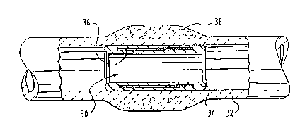
Figure 1 shows a longitudinal cross-section of
15 a stent provided with a radiation dosimeter.
Figure 2 shows a longitudinal cross-section of
a stent provided with a detector for the purpose of
detecting a parameter of the body fluids flowing past.
Figure 3 illustrates a schematic diagram of the
20 components used in the embodiment according to figure 2.
Figure 1 shows a longitudinal cross-section of
a stent 30 received in a body vessel 32, in which a film-
shaped radiation dosimeter 36 has been received in the
body of the stent 34. Such a stent may for instance be
25 placed inside a body vessel at the site of a tumour 38
surrounding this vessel and to be irradiated by means of
an external source and will make it possible, on removal
of the stent, to accurately establish the radiation dose
to which the tumour has been exposed.
It is also possible to use the stent according
to the invention in order to determine a parameter of the
body fluids flowing past. Figure 2 and 3 relate to a
stent suitable for such a purpose, of which a
longitudinal cross-section is illustrated in figure 2.
The stent 42 received in the body vessel 40 is
provided with a detection element 44, for instance a
measuring device for the purpose of measuring the flow
rate of body fluids flowing past the stent, such as for

CA21 60407
instance blood. As can be seen in figure 3, this
measuring device 44 is connected to a signal processing
circuit 46 of which the signal at the exit 48 is a
measure of the flow rate.
This signal is fed to a coding and transmission
circuit 50 which excites a transmission coil 52 received
inside the stent. The electromagnetic radiation emitted
carries - by means of modulation for instance -
information as regards the measuring signal of the
10 detector 44.
The power supply of the device may consist of a
miniature battery not shown here, or it is possible to
use a excitation coil 54 arranged inside the stent which
is excited from the outside by means of electromagnetic
15 radiation so that an alternating voltage is generated in
the coil 54 which is rectified by means of a diode 56.
It may be clear that in addition to the
examples described above, a great many other embodiments
and applications are possible.

Representative Drawing
A single figure which represents the drawing illustrating the invention.
Administrative Status

2024-08-01:As part of the Next Generation Patents (NGP) transition, the Canadian Patents Database (CPD) now contains a more detailed Event History, which replicates the Event Log of our new back-office solution.

Please note that "Inactive:" events refers to events no longer in use in our new back-office solution.

For a clearer understanding of the status of the application/patent presented on this page, the site Disclaimer , as well as the definitions for Patent , Event History , Maintenance Fee  and Payment History  should be consulted.

Event History

Description Date
Inactive: IPC removed 2021-09-23
Inactive: IPC removed 2021-09-22
Inactive: IPC assigned 2021-09-22
Inactive: IPC removed 2021-09-22
Inactive: First IPC assigned 2021-09-22
Inactive: IPC expired 2013-01-01
Inactive: IPC removed 2012-12-31
Inactive: IPC from MCD 2006-03-12
Inactive: Status info is complete as of Log entry date 2003-01-15
Application Not Reinstated by Deadline 1999-10-12
Time Limit for Reversal Expired 1999-10-12
Deemed Abandoned - Failure to Respond to Maintenance Fee Notice 1998-10-13
Application Published (Open to Public Inspection) 1996-04-14

Abandonment History

Abandonment Date Reason Reinstatement Date
1998-10-13

Maintenance Fee

The last payment was received on 1997-10-01

Note : If the full payment has not been received on or before the date indicated, a further fee may be required which may be one of the following

  • the reinstatement fee;
  • the late payment fee; or
  • additional fee to reverse deemed expiry.

Please refer to the CIPO Patent Fees web page to see all current fee amounts.

Fee History

Fee Type Anniversary Year Due Date Paid Date
MF (application, 2nd anniv.) - standard 02 1997-10-14 1997-10-01
Owners on Record

Note: Records showing the ownership history in alphabetical order.

Current Owners on Record
CORDIS EUROPA N.V.
Past Owners on Record
HENDRIK GLASTRA
Past Owners that do not appear in the "Owners on Record" listing will appear in other documentation within the application.
Documents

To view selected files, please enter reCAPTCHA code :


To view images, click a link in the Document Description column. To download the documents, select one or more checkboxes in the first column and then click the "Download Selected in PDF format (Zip Archive)" or the "Download Selected as Single PDF" button.

List of published and non-published patent-specific documents on the CPD .

If you have any difficulty accessing content, you can call the Client Service Centre at 1-866-997-1936 or send them an e-mail at CIPO Client Service Centre.


Document
Description 
Date
(yyyy-mm-dd) 
Number of pages   Size of Image (KB) 
Abstract 1996-04-14 1 11
Cover Page 1996-06-12 1 17
Description 1996-04-14 3 117
Drawings 1996-04-14 1 26
Claims 1996-04-14 1 24
Representative drawing 1997-12-19 1 10
Reminder of maintenance fee due 1997-06-12 1 109
Courtesy - Abandonment Letter (Maintenance Fee) 1998-11-10 1 184
Courtesy - Office Letter 1995-11-20 1 13