Note: Descriptions are shown in the official language in which they were submitted.
W094l257~ PCT/SE94/00372
21~0790
Drill tube element
The present invention relates to a drill tube element
for percussive top hammer drilling, said element having
a longitudinal extension, said element further having a
male thread at one end and a female thread at the other
end, said threads being used to connect tube elements
with each other to form a drill string that transfers
impact energy from the top hammer to a drill bit
connected to the end of the drill string opposite from
the top hammer, said drill tube element having
internal, longitudinally through-going, passage means
for flushing medium.
From EP-B-0 126 740 is previously known a method
employed in long-hole drilling and a drill rod system.
Said prior art technique uses drill tube elements
having a considerably larger diameter than conventional
drill rods also used for percussive top hammer
drilling. This is illustrated in Figs.4-9 of
EP-B-0 126 740. EP-B-0 126 740 is incorporated in the
present application by way of reference.
When drilling with drill tube elements according to
EP-B-0 126 740 the direction of the drilling can either
be downwards, horisontal or upwards. The drilling fluid
when drilling underground is normally water with some
additive e.g. for lubrication purposes. Since the drill
tube elements have a relative large inner diameter each
drill tube element holds a considerable amount of
water.
AS the length of the drilled hole increases the drill
string is extended by new drill tube elements that are
wog4/2~7~21~ ~ 7 9 0 PCT/SE94/00372
.
connected to the drill tube elements of the drill
string by thread couplings, see Figs.10-14 of
EP-B-0 126 740. When drilling upwards with an equipment
according to EP-s-o 126 740 it is necessary to arrange
for the water to stay in the drill tube elements of the
drill strlng when a new drill tube element is connected
to the drill string. This can be arranged with some
type of a non-return valve. However, since it is often
necessary also to drill downwards with the same
equipment, said nGn-return valve arrangement must only
work in one direction, i.e. the water is not allowed to
flow downwards when drilling upwards but the water must
be allowed to flow downwards when drilling downwards.
From SE-B-456 269 is previously known a non-return
valve arrangement at a connection between two tubes,
said connection being effected by friction welding. The
non-return valve arrangement includes a ball and a
holder device, said holder device being mounted in
connection with the friction welding and axially locked
by an upset from the welding cooperating with a groove
in the holder. However, this non-return valve
arrangement is especially adapted to be used in
connection with friction welding of tubes and therefore 25 not suitable for elements being connected to each other
by thread couplings.
The aim of the present invention is to present a non-
return valve means that allows a drill tube element as
specified above to be used for drilling in all
directions. This is achieved with a non-return valve
that has been given the characteristics of the
accompanying claims.
W094/257~ ~1~ 0~ 3 ~ PCT/SE94/00372
Below embodiments of the non-return valve according to
the present invention will be described with reference
to the accompanying drawings, where Fig.1 shows a
preferred embodiment of a drill tube element according
to the present invention, said element being in
position for drilling upwards; Fig.la shows a section
along Ia-Ia in Fig.1; Fig.2 shows an exploded view of
the upper part of the drill tube element according to
Fig.1; Fig.3 shows the drill tube element according to
lG Fig.1 in position for drilling downwards; Fig.4 shows
an alternative embodiment of a drill tube element
according to the present invention, said element being
in position for drilling upwards; Fig.4a shows a
section along IVa-IVa in Fig.4; Fig.5 shows an exploded
view of the upper part of the drill tube element
according to Fig.4; Fig.6 shows the drill tube element
according to Fig.4 in position for drilling downwards
and Figs.7a-7d show different embodiments of a tube
that constitutes an essential detail of the present
invention.
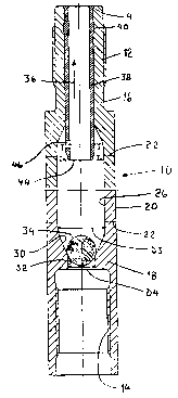
The drill tube element 10 in Fig.1 is provided with a
male thread 12 at one end and a female thread 14 at the
other end. The portions 16, 18 holding the threads 12,
14 are separate portions that are connected to the
central portion 20 of the drill tube element 10, e.g.
by a friction weld 22. This technique is known from
EP B-0 126 740.
As is most clearly shown in Fig.2 the male thread
portion 16 is provided with a first restriction 24
having a largest diameter D1 equal to the diameter of a
first flushing bore 26 of the central portion 20 and a
smallest diameter D2 equal to the diameter of a second
w094l25723 51~ a 7 ~ O PCT/SE94/00372
flushing bore 28 of the male thread portion 16.
The female thread portion 18, see Fig.1, is also
provided with a second restriction 30 having a largest
diameter D3 equal to the diameter of the first flushing
bore 26, i . e. the diameters D1 and D3 are equal. The
smallest diameter of the restriction 30 is equal to the
diameter D4 of a third flushing bore 32 extending
between the second restriction 30 and the internal
lû thread 14.
A ball 34 of a suitable material, preferably metal, is
located inside the central portion 20 of the drill tube
element 10. The diameter D5 of the ball 34 is smaller
than the diameter D2 of the second flushing bore 28 and
larger than the diameter D4 of the third flushing bore
32. Having the diameter D5 of the ball 34 smaller than
the diameter D2 of the second flushing bore 28 makes it
possible to insert the ball 34 through the second
flushing bore 28. Since the diameter D5 of the ball 34
is larger than the diameter D4 of the third flushing
bore 32 the ball 34 will cooperate with the restriction
30 to provide a non-return valve for the flushing
medium, i.e. normally water.
In order to maintain the ball 34 within the central
portion 20 but still allowing the flushing medium to
flow in direction of the arrow 36 a barrier means in
the shape of a tube 38 is mounted in the second
3û flushing bore 28, said tube 38 having an internal
diameter D6, see Fig. 2, that is smaller than the
diameter D5 of the ball 34. The tube 38 is made of a
suitable material, preferably plastic or soft metal,
e.g. alumina. It is important that the material of the
W094l257~ 21~ 0 PCT/SE94100372
_
tube 38 is essentially lighter than the material of the
drill tube element 10, i.e. the tube 38 should have a
substantially lower density than the drill tube element
10. In order to lock the tube 38 in the second flushing
bore 28 against axial displacement the tube 38 is
provided with protrusion means, preferably an annular
protrusion 40, that cooperates with groove means,
preferably an annular groove 42, in the second flushing
bore 28. As a further means to prevent the tube 38 from
lû being displaced downwardly in Fig.1 the tube 38 is
provided with a shoulder 41. The dimension of the tube
38 is such that when the inner end 44 of the tube 38
cooperates with the ball 34 a barrier for the flushing
medium to enter through said inner end 44 in direction
of the arrow 36 is provided. However, in order to allow
flushing medium to flow in direction of the arrow 36
although the ball 34 is cooperating with the inner end
44 of the tube 38, said tube 38 is provided with a
number of openings 46 in its wall area between the
inner end 44 and the transition between the first
restriction 24 and the second flushing bore 28. The
total area of said openings 46 should at least be equal
to the internal cross sectional area of the tube 38 in
order to avoid a flow restriction.
The valve arrangement described above functions in the
following way. The flushing medium always flows in
direction of the arrow 36.
When upward-drilling is effected the male thread 12 is
at the upper end of the drill tube element 10. When
drilling fluid travels in direction of the arrow 36 the
ball 34 will be lifted from the position shown in
Fig.1. However, when drilling is interrupted, e.g. for
W094/25723 21~ Oi~ PCT/SE94/00372
connecting a new drill tube element 10 to the drill
string, then the pumping of the drilling fluid in
direction of the arrow 36 is also interrupted. This
means that the ball 34, due to gravity and pressure
from the drilling fluid inside the drill tube element
10, will engage the restriction 30 to create a non-
return valve. The flushing medium above the ball 34 in
each drill tube element 10 will thus be maintained in
the drill tube element 10.
1~)
In Fig.3 downward-drilling is disclosed. In such a
drilling mode the ball 34 will due to gravity and
influence from the drilling fluid engage the inner end
44 of the tube 38. Although flushing medium will not
enter via the inner end 44 of the tube 38, due to the
cooperation between the ball 34 and said inner end 44,
it is possible for the flushing medium to flow, via the
openings 46, in the direction of the arrow 36 through
the tube 38.
It is also possible within the scope of the present
invention to locate the non-return valve means in the
area of the male thread. In Figs.4-6 such an embodiment
is disclosed. The drill tube element 10' in Fig.4 is
provided with a male thread 12' at one end and a female
thread 14' at the other end. The portions 16', 18'
holding the threads 12', 14' are separate portions that
are connected to the central portion 20' of the drill
tube element 10', e.g. by a friction weld 22'. This
technique is known from EP-B-0 126 740.
As shown most clearly in Fig.4 the male thread portion
16' is provided with a first restriction 24' having a
largest diameter Dl' equal to the diameter of a first
W094/257~ PCT/SE94100372
21~'~79~
flushing bore 26' of the central portion 20' and a
smallest diameter D2' equal to the diameter of a second
flushing bore 28' of the male thread portion 16'.
As is most clearly shown in Fig.5 the female thread
portion 18' is also provided with a second restriction
30' having a largest diameter D3' equal to the diameter
of the first flushing bore 26', i.e. the diameters D1'
and D3' are equal. The smallest diameter of the
restriction 30~ is equal to the diameter D4' of a third
flushing bore 32' extending between the second
restriction 30' and the internal thread 14'.
A ball 34' of a suitable material, preferably metal, is
located inside the central portion 20' of the drill
tube element 10'. The diameter D5~ of the ball 34' is
smaller than the diameter D4' of the third flushing
bore 32' and larger than the diameter D2' of the second
flushing bore 28'. Having the diameter of the ball 34'
smaller than the diameter D4' of the third flushing
bore 32' makes it possible to insert the ball 34'
through the third flushing bore 32'. Since the diameter
D5' of the ball 34' is larger than the diameter D2' of
the second flushing bore 28' the ball 34' will
cooperate with the restriction 24' to provide a non-
return valve for the flushing medium, i.e. normallywater.
In order to maintain the ball 34~ within the central
portion 20' but still allowing the flushing medium to
flow in direction of the arrow 36' a barrier means in
the shape of a tube 38' is mounted in the third
flushing bore 32'. Said tube 38' is made of a suitable
material, preferably plastic or soft metal, e.g.
alumina. In order to lock the tube 38' in the third
W094t257~ 21~ 0 7 ~ ~ PCT/SE94/00372
flushing bore 32' against axial displacement upwards in
Fig.4 the tube 38 ! iS provided with a protrusion 40'
that cooperates with the transition edge between the
restriction 30' and the third flushing bore 32~. In
order to prevent axial displacement downwards in Fig.4
the tube 38' is provided with an annular shoulder 41'
that cooperates with the transition edge between a
thread clearance 42' in the internal female thread 14
and the third flushing bore 32'. The dimension of the
tube 38' is such that when the inner end 44' of the
tube 38' cooperates with the ball 34' a barrier for the
flushing medium to enter through said inner end 44' in
direction of the arrow 36' is provided. However, in
order to allow flushing medium to flow in direction of
the arrow 36' although the ball 34' is cooperating with
the inner end 44' of the tube 38', said tube 38' is
provided with a number of openings 46' in the area
between the inner end 44' and the transition between
the first restriction 24' and the second flushing bore
28'. The total area of said openings 46' should at
least be equal to the internal cross sectional area of
the tube 38' in order to avoid a flow restriction.
The embodiment according to Figs.4-6 functions in
prlncipally the same way as the embodiment according to
Figs.1-3 described above. Thus reference to the
description above is made in that respect. In this
connection it should, however, be mentioned that when
upward-drilling is effected, see Fig.4, the female
thread 14' is at the upper end of the drill tube
element 10' and when downward-drilling is effected, see
Fig.6, the male thread 12' is at the upper end of the
drill tube element 10'.
W094/257~ PCT/SE94/00372
21~0~ 0
Common for the two described embodiments is that all of
the restrictions 24,30j24',30' for the flushing medium,
some of said restrictions cooperating with a ball, are
integral with the drill tube elements lOjlO'. This is
necessary since the drill tube elements lOjlO' are used
for percussive drilling. If the restrictions were in
the shape of separate elements connected to the drill
tube elements e.g. by a thread coupling, said coupling
would in a short time be destroyed by the percussive
energy.
For both embodiments described above the arrangements
with the openings 46; 46' can be varied within the
scope of the present invention. In Figs.7a-7d further
possible embodiments of the tube 38 are shown.
In Fig.7a the tube 38 has the same arrangement of
openings 46 as the tube 38 of Figs.1-3, i.e. the
openings 46 are circular and located on the same level.
However, the tube 38 according to Fig.7a has no annular
protrusion 40 or shoulder 41 but the tube 38 has a
slightly conical outer shape, i.e. the diameter of the
tube 38 increases towards the end of the tube 38 remote
from the openings 46. The conical shape ensures that a
proper press fit is established when mounting the tube
38 to assure that a locking against axial displacement
is provided.
In Fig.7b the tube 38 has openings 46 that are circular
but located on different levels.
In Fig.7c the tube 38 has openings 46 that are extended
in the longitudinal direction of the tube 38.
W094/25723 ~ 5 ~ ~ PCT/SE94/00372
In Fig. 7d the tube 38 is provided with openings 46 in
the shape of slots that are open at the end of the tube
38 that cooperates with the ball 34.
The arrangements of openings 46 shown in Figs.7a-7d are
only exemplifying and can of course also be applicable
to the tube 38' disclosed in Figs.4-6.
One major advantage of the present invention is that
10 the non-return valve means can easily be mounted in or
dismounted from the drill tube elements 10;10'. This
means that one can use the same drill tube element
10jl0' regardless if a non-return valve means is
necessary or not. If there is no need for a non-return
valve means the drill tube element 10jl0' is used
without mounting the ball 34;34' and the barrier means
38j38'. On the other hand if a non-return valve means
is necessary the ball 34;34' and the barrier means
38j38' are readily mounted.