Language selection

Search

Patent 2160831 Summary

Third-party information liability

Some of the information on this Web page has been provided by external sources. The Government of Canada is not responsible for the accuracy, reliability or currency of the information supplied by external sources. Users wishing to rely upon this information should consult directly with the source of the information. Content provided by external sources is not subject to official languages, privacy and accessibility requirements.

Claims and Abstract availability

Any discrepancies in the text and image of the Claims and Abstract are due to differing posting times. Text of the Claims and Abstract are posted:

  • At the time the application is open to public inspection;
  • At the time of issue of the patent (grant).
(12) Patent Application: (11) CA 2160831
(54) English Title: METHOD FOR PROTECTING OBJECTS, ESPECIALLY SHIPS, THAT EMIT A RADIATION, PARTICULARLY INFRARED RADIATION, AGAINST MISSILES
(54) French Title: METHODE POUR PROTEGER DES OBJETS RAYONNANTS, LES NAVIRES PAR EXEMPLE, QUI EMETTENT PLUSIEURS RAYONNEMENTS, NOTAMMENT INFRAROUGE, CONTRE LES ATTAQUES DE MISSILES
Status: Deemed Abandoned and Beyond the Period of Reinstatement - Pending Response to Notice of Disregarded Communication
Bibliographic Data
(51) International Patent Classification (IPC):
  • F41H 11/02 (2006.01)
  • F42B 12/70 (2006.01)
(72) Inventors :
  • WARDECKI, NORBERT (Germany)
(73) Owners :
  • BUCK WERKE GMBH & CO.
(71) Applicants :
  • BUCK WERKE GMBH & CO. (Germany)
(74) Agent: G. RONALD BELL & ASSOCIATES
(74) Associate agent:
(45) Issued:
(22) Filed Date: 1995-10-18
(41) Open to Public Inspection: 1996-04-22
Availability of licence: N/A
Dedicated to the Public: N/A
(25) Language of filing: English

Patent Cooperation Treaty (PCT): No

(30) Application Priority Data:
Application No. Country/Territory Date
P 44 37 729.0-15 (Germany) 1994-10-21

Abstracts

English Abstract


A method for protecting an object such as a ship emitting radiation
against a missile equipped with an intelligent homing head for sensing the radiation
has the steps of launching a diversionary projectile body away from the object and
of dispersing the projectile body at a removed location to form a dummy target
cloud. It has the further interposed step of activating a radiation means on theprojectile body immediately after launching that body. The radiation means radiates
an energy form corresponding to the energy form from the later dummy target cloud,
and continues to radiate that energy form until the dummy target cloud has formed
and built to a sufficient level. A series of projectile bodies may be launched with a
temporal and/or spatial offset, creating a continuous diversionary radiation path.


Claims

Note: Claims are shown in the official language in which they were submitted.

THE EMBODIMENTS OF THE INVENTION IN WHICH AN EXCLUSIVE
PROPERTY OR PRIVILEGE IS CLAIMED ARE DEFINED AS FOLLOWS:
1. A method for protecting an object emitting radiation against
a missile that is equipped with an intelligent homing head for sensing the
radiation, comprising the steps of:
launching a projectile body loaded with a combustible projectile
means from a launcher means installed on the object or in the proximity thereof;and,
dispersing the projectile body and simultaneously igniting and
distributing the projectile means next to a target in a region of homing optics of
the homing head, a dummy target cloud thereby being formed having a higher
radiation capacity than the object;
wherein, between the steps of launching the projectile body and dispersing the
projectile body, there is interposed the further step of:
activating a radiation means on the projectile body immediately
after launching that body, the radiation means radiating an energy form
corresponding to the energy form from the later dummy target cloud in an
intensity relevant for the homing head, the radiation means continuing to
operate until radiation from the dummy target cloud has built to an intensity
relevant for the homing head.
2. A method as in claim 1, wherein the target is a ship.
3. A method as in claim 1, wherein the radiation is infrared
radiation.
4. A method as in claim 1, wherein the target is a ship and the
radiation is infrared radiation.

5. A method as in claim 1, wherein the homing head is capable
of performing at least one of the processes of scanning, imaging, correlating
and spectrally-filtering.
6. A method as in claim 1, wherein the target is a ship, the
radiation is infrared radiation, and the homing head is capable of performing atleast one of the processes of scanning, imaging, correlating and spectrally-
filtering.
7. A method as in claim 1, 2, 3, 4, 5 or 6, wherein the radiation
means radiates continuously.
8. A method as in claim 1, 2, 3, 4, 5 or 6, wherein the radiation
means radiates in clocked fashion.
9. A method as in claim 1, 2, 3, 4, 5 or 6, wherein the steps
of the respective claim are repeated for the launching of further projectile bodies
at a temporal and/or spatial offset, the radiation means on the further projectile
bodies being activated and the projectile bodies being subsequently dispersed
such that a chain of further, successive dummy target clouds arises, each
propagating from the respectively-preceding dummy target cloud, the dummy
target clouds being connected by energy emission trails relevant for the homing
head and caused by the respective radiation means.
10. A method as in claim 1, 2, 3, 4, 5 or 6, wherein the steps
of the respective claim are repeated for the launching of further projectile bodies
at a temporal and/or spatial offset, the radiation means on the further projectile
bodies being activated and the projectile bodies being subsequently dispersed
such that a chain of further, successive dummy target clouds arises, each
propagating from the respectively-preceding dummy target cloud, the dummy
target clouds being connected by energy emission trails relevant for the homing

head and caused by the respective radiation means, and wherein the respective
radiation means radiate continuously.
11. A method as in claim 1, 2, 3, 4, 5 or 6, wherein the steps
of the respective claim are repeated for the launching of further projectile bodies
at a temporal and/or spatial offset, the radiation means on the further projectile
bodies being activated and the projectile bodies being subsequently dispersed
such that a chain of further, successive dummy target clouds arises, each
propagating from the respectively-preceding dummy target cloud, the dummy
target clouds being connected by energy emission trails relevant for the homing
head and caused by the respective radiation means, and wherein the respective
radiation means radiate in clocked fashion.

Description

Note: Descriptions are shown in the official language in which they were submitted.


2160831
METHOD FOR PROTECTING OBJECTS, ESPECIALLY SHIPS,
THAT EMIT A RADIATION, PARTICULARLY INFRARED
RADIATION, AGAINST MISSILES
The invention relates to a method for protecting an object that
emits radiation against missiles that are equipped with intelligent homing heads.
More particularly, it relates to a method in which a dummy target cloud of higher
radiation capacity than the object is created from a dispersal of a projectile body
5 that has been fired from the object or from the object's proximity.
This method has been particularly applied to protect ships that emit
infrared radiation against missiles equipped with a variety of scanning, imaging,
correlating and/or spectrally-filtering intelligent homing heads.
Such a method, for example protecting S-boats from missiles
10 armed with infrared homing heads, forms the basis of the invention disclosed
in German Published Application 34 21 734 A1 and European Letters Patent 0
240 819 B1. It exploits the functioning of the homing heads on missiles in the
following way: the homing heads have optics that have a comparatively large
aperture angle at the beginning of what is referred to as the 'seek phase', which
15 usually begins at a range of approximately 10 to 15 kilometres from an object.
For example, the homing heads can cover a seek region having an azimuth of
approximately 3000 to 5000 metres and an elevation of approximately 300 to
-- 500 metres. After recognizing the object, the homing head locks onto the object
during the course of the continued flight of the missile, this being referred to as
20 'lock-on'. After lock-on, the angle of view of the optics of the homing head
diminishes greatly both in azimuth and in elevation. At a range of approximately5 to 8 kilometres, at which the lock-on to the object usually commences, the
area covered by the seek window of the homing head only amounts to about
100 metres in azimuth and about 50 metres in elevation. Until impact this area
25 continually reduces in size. An infrared diversionary dummy target cloud can
therefore only be a distance of about 40 metres to 50 metres to the side of the
radiation centre of the object, and only about 25 metres to 30 metres above the
object, if it is to be acquired by the already-diminished angle of view of the

21~8~1
optics of the homing head. Additionally, the dummy target cloud must comprise
a significantly higher infrared radiation capacity than the actual object.
The traditional method, however, has the disadvantage that a
diverting effect, and thus protection, does not exist during the time between the
- 5 firing of a projectile that is to become the dummy target cloud and the actual
formation of that target cloud. Over and above this, a spatial distance is
established between the firing location and the effective location (dispersal
point) that is accompanied by more stringent demands for the positioning of the
dummy target in the field of view of the homing head -- particularly, in the
seduction case following lock-on --; otherwise, the desired diverting effect is not
realized.
German Patent 33 26 884 C2 discloses a method wherein a
shielding effect is created in the infrared region by a projectile body that
develops a hot aerosol a short time after being fired. This is a shielding or
smokescreen method that provides no possibility of leading a homing head
already locked-in to the object away from the object.
German AS 10 96 805, German Letters Patent 258 538 and
German Patent 34 21 734 A1 disclose shells that emit energy effective in the
infrared range during flight; however, no teachings of the diverting or homing
heads can be found therein.
~- The invention has an object of improving the - dummy target
effectiveness of the of the previous methods in that a homing head locked onto
an object to be protected can be reliably diverted away from the object.
This object is achieved by including a radiation means in the
projectile body, and activating that radiation means upon launch of the projectile
body. The radiation means radiates an energy form corresponding to that of the
later dummy target in an intensity relevant for the homing head, beginning
immediately after the launch and lasting until the energy form of the dummy
target has been built up to an intensity relevant for the homing head.
It can be provided that the radiation means radiates continuously,
or in a clocked fashion. Further ones of the projectile bodies may be launched

2160821
at a temporal and/or spatial offset, with the radiation means on the further
projectile bodies being activated and the projectile bodies being subsequently
dispersed such that a chain of further, successive dummy target clouds arises.
Each cloud propagates from the respectively-preceding cloud. The clouds are
connected by energy emission trails relevant for the homing head and caused
by the respective radiation means.
The radiation means in the invention can comprise a pyrotechnical
assembly, for example a gas generator, a flare assembly or a rocket engine.
The invention is based on a surprising perception that a provisional
dummy target irradiates the rest of the object to be protected, and is identified
by the homing head upon launch of the projectile body as being generated in
the silhouette of the object to be protected itself. The provisional dummy target,
which is generated with the radiation means that is immediately activated,
decisively improves the defence efficiency of the known methods. After
generation of the provisional dummy target, the homing head no longer "sees"
the rest of the object to be protected, but only sees the provisional dummy
target. As the projectile body moves away from the object to be protected, the
homing head follows the provisional dummy target -- formed like tracer
ammunition by the radiation means -- which then moves out of the silhouette of
the object to be protected and is reliably diverted into the later, ultimate dummy
target. A diversion of the homing head can thus also ensue when the dummy
target blooms outside of the field of view of the homing head, for example due
to faulty positioning. A simplification of the self-defence system thereby derives,
whereby the protective effect takes effect immediately after the launch.
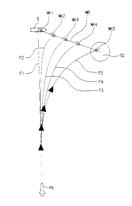
The inventive method is set forth in greater detail below with
reference to the accompanying Figure 1, which shows the sequence of steps
of the inventive method with reference to a homing head approaching an object.
As Figure 1 shows, a guided missile FK armed with an infrared
homing has located a ship S and first approaches the ship S on a flight path F1.At a time when the missile FK has already locked onto the ship S, a projectile
body is launched from a position WK1 in a direction toward the position of a

216083~
dummy target SZ; the projectile body is launched along a launch path WB
proceeding from the ship S to be protected. A rocket engine, radiating
continuous heat similar to tracer ammunition, has already been fired in the
position WK1 with the launch of the projectile body; as a result thereof, the ship
5 S is already irradiated for the infrared homing head of the missile FK upon
launch of the projectile body in the position WK1. Consequently, the missile FK
already draws a bead thereon in the projectile body position WK1, and then
continuously alters its flight path from F1 to F2, F3, F4 and F5 as the projectile
body continuously moves through the positions WK2, WK3 and WK4 along the
10 flight path WB in the direction toward the dummy target position SZ (projectile
body position WK5). The projectile body then forms the dummy target SZ,
where the missile FK strikes the dummy target.
Both individually as well as in arbitrary combination, the features
of the invention disclosed in the above specification, in the drawing as well as15 in the claims, can be critical for the realization of the various embodiments of
the invention.

Representative Drawing
A single figure which represents the drawing illustrating the invention.
Administrative Status

2024-08-01:As part of the Next Generation Patents (NGP) transition, the Canadian Patents Database (CPD) now contains a more detailed Event History, which replicates the Event Log of our new back-office solution.

Please note that "Inactive:" events refers to events no longer in use in our new back-office solution.

For a clearer understanding of the status of the application/patent presented on this page, the site Disclaimer , as well as the definitions for Patent , Event History , Maintenance Fee  and Payment History  should be consulted.

Event History

Description Date
Time Limit for Reversal Expired 1999-10-18
Application Not Reinstated by Deadline 1999-10-18
Deemed Abandoned - Failure to Respond to Maintenance Fee Notice 1998-10-19
Application Published (Open to Public Inspection) 1996-04-22

Abandonment History

Abandonment Date Reason Reinstatement Date
1998-10-19

Maintenance Fee

The last payment was received on 1997-10-02

Note : If the full payment has not been received on or before the date indicated, a further fee may be required which may be one of the following

  • the reinstatement fee;
  • the late payment fee; or
  • additional fee to reverse deemed expiry.

Please refer to the CIPO Patent Fees web page to see all current fee amounts.

Fee History

Fee Type Anniversary Year Due Date Paid Date
MF (application, 2nd anniv.) - standard 02 1997-10-20 1997-10-02
Owners on Record

Note: Records showing the ownership history in alphabetical order.

Current Owners on Record
BUCK WERKE GMBH & CO.
Past Owners on Record
NORBERT WARDECKI
Past Owners that do not appear in the "Owners on Record" listing will appear in other documentation within the application.
Documents

To view selected files, please enter reCAPTCHA code :


To view images, click a link in the Document Description column. To download the documents, select one or more checkboxes in the first column and then click the "Download Selected in PDF format (Zip Archive)" or the "Download Selected as Single PDF" button.

List of published and non-published patent-specific documents on the CPD .

If you have any difficulty accessing content, you can call the Client Service Centre at 1-866-997-1936 or send them an e-mail at CIPO Client Service Centre.


Document
Description 
Date
(yyyy-mm-dd) 
Number of pages   Size of Image (KB) 
Cover Page 1996-03-11 1 19
Abstract 1996-03-11 1 21
Description 1996-03-11 4 195
Drawings 1996-03-11 1 10
Claims 1996-03-11 3 98
Representative drawing 1999-08-05 1 9
Reminder of maintenance fee due 1997-06-19 1 109
Courtesy - Abandonment Letter (Maintenance Fee) 1998-11-16 1 184
Fees 1997-10-02 1 49