Note: Descriptions are shown in the official language in which they were submitted.
~160846
NATURAL GAS ENRICHMENT PROCESS
Field of the Invention
This invention relates to a process for increasing the content of
10 hydrocarbon gases in a hydrocarbon gas stream containing other gases.
More particularly this invention relates to a process for the purification
of a natural gas stream by the selective adsorption of hydrocarbon gases,
the rejection of non-hydrocarbon gases, and the subsequent desorption of
hydrocarbon gases to produce an enriched natural gas stream. In a
15 particular embodiment this invention relates to the separation of nitrogen
from a natural gas stream.
Background of the Invention
The problem that exists is to provide a way to use natural gas
20 supplies that have a content of natural gas of from about 50 percent to 95
percent by volume hydrocarbons with the remainder primarily being
nitrogen. A natural gas product, which consists primarily of methane, but
which can contain small quantities of higher hydrocarbons and significant
amounts of nitrogen cannot be sold as a natural gas fuel unless it contains
25 at least 1000 Btu per standard cubic foot(scf) of natural gas. This is a
standard in the industry. A consequence of this standard is that there are
supplies of natural gas in the ground that cannot be used. These are wells
that have been capped for lack of a market for this quality of gas. The
natural gas content of these supplies range down to 50 percent by volume
30 and lower. These supplies must be upgraded for use. The various other
contaminating gases must be removed.
21608~
A classical way to remove contaminating gases from a natural gas
stream is through liquefaction. In these processes the contaminating
gases, which primarily is nitrogen, are separated from the hydrocarbon
gases and vented to the atmosphere. If the natural gas contains
5 quantities of sulfurous gases such as hydrogen sulfide, and water and
carbon dioxide these can be removed in a prior step by scrubbing with
monoethanolamine to remove hydrogen sulfide followed by drying with
diethylene glycol, triethylene glycol, alumina, silica gel or zeolites.
Optionally, a pressure swing adsorption technique such as disclosed in
10 European Patent 394,947A can be used to remove carbon dioxide. In
liquefaction processes the gas stream containing primarily methane but
also amounts of higher hydrocarbons and nitrogen is cooled to recover the
higher hydrocarbons as liquids and the stream then further cooled to
liquify methane which is recovered in pipeline purity and used. The
15 remaining gas, nitrogen, can be collected as a product or vented. As an
option the methane/nitrogen stream can be processed to recover helium if
helium is present in a sufficient amount.
It also is known to enrich natural gas using pressure swing
adsorption techniques. In U.S. Patent 5,171,333 there is disclosed a
20 technique using four adsorbent beds, each of which contains a faujasite
adsorbent. Each bed in sequence goes through an adsorption step, a
desorption step by lowering the pressure and then a repressurization step
to bring a bed back up to adsorption pressure. The adsorption step is
conducted at about 100 to 500 psia and consists of passing a feed gas into
25 an adsorbent bed. The desorption step consists of cocurrently
depressurizing an adsorbent bed and passing the gas to a bed undergoing
repressurization, further cocurrently depressurizing the adsorbent bed
and passing the gas as a purge gas to a bed undergoing purging,
21~0~4~
countercurrently depressurizing and collecting a methane/ethane stream
and countercurrently purging the adsorption zone with a purge gas from
another adsorbent bed and recovering ethane. The repressurization step
consists of repressurizing the adsorbent bed by cocurrently passing a
5 depressurization gas into the adsorbent bed and further repressurizing the
adsorbent bed by passing a portion of the adsorption effluent from another
adsorbent bed to this adsorbent bed.
In U.S. Patent 5,174,796 there is disclosed a pressure swing
adsorption process for enriching a natural gas stream which contains
10 nitrogen. A carbon adsorbent is used and the natural gas is preferentially
adsorbed. The process steps consist of cocurrent adsorption, a first
cocurrent depressurization and the use of a part of this gas to
repressurize another adsorbent bed, cocurrently depressurizing the
adsorbent bed to a yet lower pressure and withdrawing a fuel gas stream,
15 countercurrently depressurizing the adsorbent bed and recovering a
product gas, countercurrently purging the adsorbent bed and recovering
additional product gas, then countercurrently repressurizing the
adsorbent bed in two repressurization steps with nitrogen gas from
another adsorbent bed. This repressurization brings the adsorbent bed up
20 to about the feed gas pressure.
These are interesting processes but they are not highly efficient in
the enrichment of natural gas. The various liquefaction processes have a
high capital cost and are expensive to operate. The pressure swing
adsorption processes to date have not optimized the recovery of the
25 methane product gas. The objective in increasing efficiency is to desorb
essentially all of the adsorbed gas in as high a purity as possible as
quickly as possible, utilizing the value of any off gases, and then put the
adsorbent bed back into production as quickly as possible. This is what is
4 ~
accomplished in the processes of the present invention. In addition, there
should be a clean separation of the nitrogen and methane. That is, there
should be essentially no methane in the nitrogen gas stream which usually
will be vented since methane is the primary product.
Brief Summary of the Invention
The present invention in a preferred embodiment is directed to the
10 enrichment of a natural gas stream to bring the natural gas stream up to
pipeline quality. Typically a pipeline quality gas must contain about 98
percent by volume hydrocarbons with essentially all of the hydrocarbons
being methane. This usually will provide a natural gas having a fuel
content of at least 1000 Btu per scf. As natural gas is recovered at the
15 wellhead it can contain from about 3 to 60 percent by volume nitrogen.
This nitrogen content must be reduced in order to bring the natural gas up
to pipeline quality.
The present technique for bringing a natural gas stream up to
pipeline quality is to utilize a pressure swing adsorption process using an
20 activated carbon adsorbent. The carbon adsorbent preferentially adsorbs
the hydrocarbons and allows the non-hydrocarbons to pass through. The
non-hydrocarbon stream can be collected or vented.
The pressure swing adsorption process comprises the use of a
plurality of adsorbent beds, preferably three to five and usually about
25 four, each sequentially going through the phases of (a) adsorption; (b)
recycle; (c) depressurization; (d) evacuation; (e) nitrogen gas
pressurization; and (f) feed recycle pressurization.
2160~4~
The adsorption phase consists of flowing the natural gas stream
cocurrently through an adsorbent bed until the adsorbed hydrocarbon front
in the adsorbent bed approaches the exit of the adsorbent bed. At this
point the feed of natural gas is stopped and the adsorbent bed is put onto
5 the recycle phase.
The recycle phase consists of compressing and cocurrently passing a
depressurization gas from another adsorbent bed that also is undergoing
regeneration into the present adsorbent bed in order to remove the natural
gas in the void space between the adsorbent particles and to desorb
10 adsorbed nitrogen. As a recycle feed gas exits the adsorbent bed in a
recycle phase it is optionally repressurized and is fed to an adsorbent bed
that now is on a natural gas adsorption phase. At the completion of the
recycle phase the void space and the adsorbent will contain more than 90
percent hydrocarbons, and preferably more than 95 percent hydrocarbons.
15 At this point the adsorbent bed undergoes a depressurization phase.
The depressurization phase comprises reducing the pressure of the
adsorbent bed and countercurrently flowing the released gas from the
adsorbent bed to a compressor which increases the pressure to about the
feed gas adsorption pressure or higher, with this gas being fed as a
20 depressurization gas to a bed which has just completed an adsorption
phase. This is a gas stream which contains more than 90 percent
hydrocarbons, and preferably more than 95 percent hydrocarbons. This
adsorbent bed then undergoes an evacuation phase.
The evacuation phase consists of reducing the pressure on the
25 adsorbent bed and flowing the gas countercurrently from the adsorbent
bed. The evacuation is conducted at a much reduced pressure, and
preferably under a vacuum of at least 20 inches of mercury and preferably
28 inches of mercury or more. The evacuation gas is a product which is
2160846
compressed to pipeline pressure. The adsorbent bed then undergoes a
nitrogen pressurization phase.
The nitrogen pressurization phase consists of countercurrently
flowing a nitrogen off gas from a bed on an adsorption phase into this
5 adsorbent bed. The absolute pressure of this adsorbent bed will rise to
about half of the operating adsorption phase pressure. The adsorbent bed
then enters a recycle feed pressurization phase which consists of flowing
the gas from the adsorbent bed on a recycle phase into this adsorbent bed.
The adsorbent bed then repeats the cycle by undergoing an adsorption step
10 by the flow of natural gas feed gas into the adsorbent bed.
Each adsorbent bed in turn undergoes the same process phases in
sequence. While one adsorbent bed is undergoing one phase, the other
adsorbent beds are undergoing other phases. The timing of the phases can
vary. However, in a preferred embodiment the recycle, depressurization
15 and evacuation phases will have about the same timing while the nitrogen
pressurization phase, feed recycle pressurization phase and adsorption
phase will have a combined timing about equivalent to each of these other
phases. Upon exiting the pressure swing adsorption process the natural
gas product will be of pipeline quality and can be introduced into a
2 0 pipeline.
The present pressure swing adsorption process conserves more
highly adsorbed product gas. This is accomplished by taking the gas from
an adsorbent bed that is being depressurized, compressing this gas to
about feed gas pressure, and flowing this gas into an adsorbent bed that
25 has completed an adsorption phase. This recycle gas removes gas of about
feed gas composition from the adsorbent bed void space and removes
nitrogen gas which has been adsorbed in the pores of the adsorbent. This
recycle feed gas then is fed to an adsorbent bed that will be undergoing an
- 21~08~C
adsorption phase. In this way the content of the more strongly adsorbed
component is maintained in the pressure swing system. The only gases
exiting the pressure swing system are the product gas and the less
strongly adsorbed secondary product. By maintaining the more strongly
5 adsorbed component in the pressure swing system until separated from
the other gases the efficiency of the system is increased.
Brief Description of the Drawings
Figure 1 sets out in a schematic form the six phases used in the
10 adsorbent bed pressure swing adsorption system.
Figure 2 is a schematic of a four adsorbent bed system for the
separation of nitrogen from a nitrogen containing natural gas stream.
Figure 3 sets out in tabular form the cycle times for a four
adsorbent bed pressure swing adsorption system for the removal of
15 nitrogen from a natural gas stream.
Detailed Description of the Invention
The present process in a preferred embodiment is directed to the
enrichment of a natural gas stream by the removal of substantially all of
20 the nitrogen gas content of this stream. The remaining component
primarily is methane. This process is a pressure swing adsorption
process wherein the hydrocarbon content of the natural gas stream is
preferentially adsorbed by the adsorbent. Preferential adsorption is the
technique where one or more substances are more strongly adsorbed than
25 other substances. In this phenomenon essentially all of the substances
are adsorbed by the adsorbent. As the adsorption progresses the more
strongly adsorbed gases occupy the space within the adsorbent. The net
result is that at the time of breakthrough of the more strongly adsorbed
21~46
component from the bed the more strongly adsorbed components to a large
extent have saturated the adsorbent bed while the less strongly adsorbed
components to a large extent have exited the adsorbent bed.
In the present pressure swing adsorption process the adsorbent
preferably is an activated carbon which includes the substances known as
carbon molecular sieves. The activated carbon can be derived from wood,
coal, coconut or petroleum sources. The requirement is that the activated
carbon have a selectivity for hydrocarbons greater than that for nitrogen
and other gases. The adsorbent characteristics that determine selectivity
for hydrocarbons include pore structure, pore size and treatment
conditions. Activated carbons that are suitable have a carbon
tetrachloride number of about 60, a surface area of more than about 1150
sq. meters/g., a density of about 0.45 g./cc. and an average particle
diameter of about 3mm to 5mm, and preferably about 4mm. However, any
adsorbent can be used as long as it has a greater selectivity for
hydrocarbons than for nitrogen. In this way the hydrocarbon content of
the natural gas is preferentially adsorbed with the nitrogen exiting the
adsorbent bed. The hydrocarbons subsequently are desorbed from the
adsorbent bed and recovered for use.
Pressure swing adsorption systems are usually comprised of two or
more adsorbent beds. The number of adsorbent beds used is the number
that provides the overall economic benefit. That is, the pressure swing
adsorption system that is selected must give the lowest overall cost
considering the capital cost of the equipment and the operating cost. In
2 5 this regard most pressure swing adsorption systems are efficient when
three to five adsorbent beds are used. In the present pressure swing
adsorption process to enrich the hydrocarbon content of a natural gas
stream three to five adsorbent beds can be used. However, it is preferred
2160846
to use four adsorbent beds. The economics are very favorable using four
adsorbent beds.
As schematically described in Figure 1 the process consists of six
phases. These are an adsorption phase, a recycle phase, a
5 depressurization phase, an evacuation phase, a nitrogen pressurization
phase and a recycle feed pressurization phase. In the Phase I adsorption
phase a natural gas feed gas along with some recycle feed gas is fed to an
adsorbent bed until the more strongly adsorbed hydrocarbon gases are
about to exit the adsorbent bed. This is breakthrough. At this point the
10 input of the natural gas feed ceases and the adsorbent bed undergoes a
recycle phase. During the recycle phase a depressurization gas from an
adsorbent bed undergoing a Phase lll depressurization phase is
compressed and flowed through an adsorbent bed on a Phase ll recycle
phase and the exiting recycle feed gas is flowed to an adsorbent bed in a
15 Phase Vl recycle feed pressurization phase and to an adsorbent bed in an
adsorption phase. This recycle feed gas has about the same composition
as the feed gas.
As adsorption progresses an adsorption front moves toward the exit
end of the adsorbent bed. Before the adsorption front the gases in the
20 adsorbent bed consist of the lightly adsorbed or non-adsorbed gases.
These are the gases that have not been adsorbed and the gases in the void
space. Behind the adsorption front the gases are primarily the feed gas
and the adsorbed gases in the adsorbent.
In a first step of regeneration this adsorbent bed undergoes the
25 Phase ll recycle phase. This removes feed gas from the void space of the
adsorbent bed and nitrogen from the adsorbent. In this recycle phase the
depressurization gas from an adsorbent bed undergoing depressurization
is compressed and flowed cocurrently through this adsorbent bed with the
~160846
1 0
effluent recycle feed gas flowed to an adsorbent bed on Phase I adsorption
phase and a phase Vl recycle pressurization. At the completion of the
recycle phase the adsorbent bed will contain 90 percent or more and
preferably 95 percent or more of the more strongly adsorbed hydrocarbon
5 components. This adsorbent bed then undergoes a Phase lll
depressurization phase.
In the Phase lll depressurization the pressure in the adsorbent bed
is reduced and an effluent gas flowed countercurrently from the adsorbent
bed. This depressurization gas is compressed to about the pressure of the
10 feed gas to the pressure swing system or higher and is fed to the
adsorbent bed that is entering a Phase ll recycle phase. The
depressurization gas will contain more than 90 percent by volume, and
preferably more than 95 percent by volume, of the more strongly adsorbed
hydrocarbon components. The adsorbent bed then undergoes a Phase IV
15 evacuation phase.
In the Phase IV evacuation phase a vacuum is drawn on the adsorbent
bed to a vacuum of more than about 20 inches of Hg and preferably to more
than about 28 inches of Hg. The evacuated gas flows countercurrently
from the adsorbent bed. This gas is comprised of the more strongly
20 adsorbed components which in the present process are hydrocarbons, and
primarily methane, which has a content of 98 percent or more by volume.
This is recovered as a product. The adsorbent bed then undergoes
repressurization to feed gas pressure.
The Phase V nitrogen pressurization phase consists of flowing the
25 less strongly adsorbed effluent nitrogen gas from an adsorbent bed on a
Phase I adsorption phase countercurrently into the adsorbent bed being
repressurized. This nitrogen gas pressurization plus the phase Vl recycle
feed pressurization by the cocurrent flow of recycle feed gas into this
~1608~6
adsorbent bed brings this adsorbent bed up to the feed gas pressure prior
to the introduction of feed gas and the start of another phase I adsorption.
Optionally there also can be a feed gas pressurization.
Figure 1 sets out in a schematic diagram the preferred four
5 adsorbent bed pressure swing adsorption system for the enrichment of the
hydrocarbon content of a natural gas stream. If this natural gas stream
contains significant amounts of hydrogen sulfide it will be pretreated by
scrubbing with monoethanolamine. The feed gas can be dried by treatment
with diethylene glycol or triethylene glycol or by passage through a bed of
10 alumina, silica or aluminosilicate zeolites. The feed to the pressure
swing adsorption system in Figure 1 will be a gas containing primarily
hydrocarbons and nitrogen. There will be minor amounts of other gases
present.
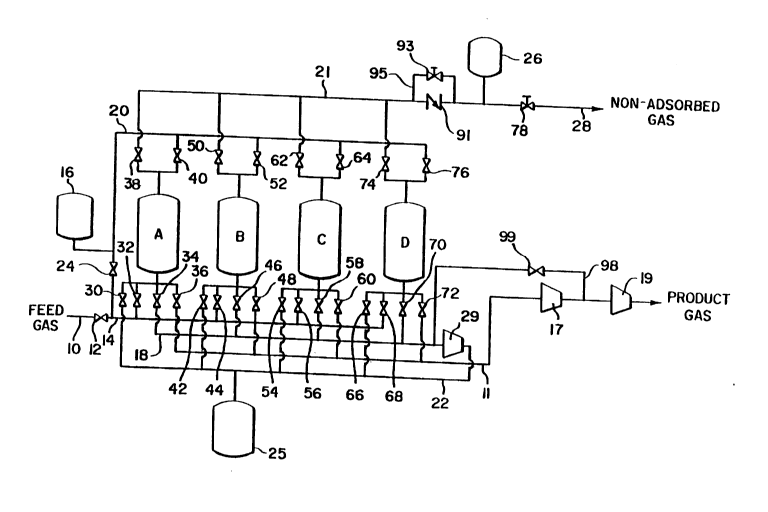
The natural gas feed gas is fed to the system at a pressure of about
15 25 to about 150 psia, and preferably about 50 psia. The feed gas passes
through inlet pipe 10 and through valve 12 and conduit 14. The system
will be illustrated with adsorbent bed A undergoing the nitrogen
pressurization, recycle feed pressurization and adsorption phases and
then describing the other phases for the other adsorbent beds. While
20 adsorbent bed A will be undergoing these three phases adsorbent beds B, C
and D will be undergoing the other phases of evacuation, depressurization
and recycle, respectively. For the nitrogen pressurization phase valve 38
on adsorbent bed A will be open with the other adsorbent bed A valves 30,
32, 34, 36 and 40 being closed. In the subsequent recycle feed
25 pressurization of adsorbent bed A valve 32 will be open with the other
adsorbent bed A valves 30, 34, 36, 38 and 40 being closed. Valve 24 also
will be open with valve 12 closed during recycle feed repressurization.
When adsorbent bed A is in an adsorption phase valve 32 will be opened
216084~
1 2
with valves 30, 34 and 36 ot adsorbent bed A closed. On the exit end of
adsorbent bed A valve 38 is open with the valve 40 being closed. The less
strongly adsorbed gas exiting adsorbent bed A during the adsorption phase
passes through valve 38 and conduit 21, with some of this less strongly
5 adsorbed gas stored in tank 26. Less strongly adsorbed gas which is not
used in the system is bled off through valve 78 and conduit 28. Tank 26
stores less strongly adsorbed gas that is to be used to pressurize
adsorbent beds in a nitrogen pressurization phase.
This completes the nitrogen pressurization, recycle feed
10 pressurization and adsorption phases for adsorbent bed A. During this
period of time adsorbent bed D has been on a Phase ll recycle phase. When
adsorbent bed D enters a recycle phase valves 66 and 76 on adsorbent bed
D are opened with all other adsorbent bed D valves 72, 68, 70 and 74 being
closed. The input depressurization gas to adsorbent bed D flows from
15 adsorbent bed C which is on a depressurization phase through valve 58 to
conduit 18 and on to compressor 29 where the pressure is raised to about
feed gas input pressure or higher. All of the other valves 54, 56, 60, 62
and 64 on adsorbent bed C are closed. The depressurization gas then
flows by conduit 22 through valve 66 and into adsorbent bed D. Tank 25 is
20 available for the storage of this gas. A recycle feed gas exits adsorbent
bed D through valve 76 and conduit 20 to the feed gas input line 14. Tank
16 stores recycle feed gas and valve 24 regulates the flow of the recycle
feed gas.
At this same time adsorbent bed B is on a phase IV evacuation
25 phase. During this phase adsorbent bed B valve 48 is open with all other
adsorbent bed B valves 42, 44, 46, 50 and 52 being closed. This adsorbent
Bed B is evacuated to more than about 20 inches of Hg vacuum and
preferably to more than about 28 inches of Hg vacuum by vacuum pump 17.
This product gas which flows through conduit 11 is more than 95 percent
2160846
1 3
more strongly adsorbed hydrocarbon gases, and preferably more than 98
percent more strongly adsorbed hydrocarbon gases. This pressure of this
product gas is then boosted to use pressure, which can be pipeline
pressure, by compressor 19.
In conduit 21 there is a check valve 91 and a throttle valve 93.
Check valve will allow flow from the adsorbent beds to tank 26 but not in
the reverse direction. Throttle valve provides a regulated flow to the
adsorbent beds during the nitrogen pressurization phases.
1 0
As an option conduit 98 connects to conduit 18 before compressor
29 and connects to conduit 11 after vacuum pump 17. This conduit 98 has
a valve 99. Valve 99 will be open depending on the hydrocarbon
concentration of the feed gas. If the feed gas has a hydrocarbon
15 concentration of less than about 75 percent by volume then valve 99 will
be opened during part of the evacuation phase. This will provide
additional gas as needed during the recycle phase. If the hydrocarbon
concentration of the feed gas is greater than about 75 percent then valve
99 will be open during part of the depressurization phase. This will
20 remove gas from the system. The objective is to provide a sufficient
amount of recycled depressurization gas during the depressurization
phase.
The phases of the process have been described for one segment of a
25 cycle. In order to complete a full cycle each of the adsorbent beds must
undergo each phase. Upon the completion of a full cycle the cycles are
then repeated. In Figure 3 there is a phase sequencing for a full cycle
which consists of 360 seconds. This is a preferred timing. The timing
21608~6
1 4
will be affected by many factors including feed stream composition,
adsorbent bed geometry and adsorbent particle size. This phase sequence
is for four adsorbent beds. Consequently, the time periods are set at 90
seconds each. In this regard one 90 seconds sequence for each adsorbent
bed consists of the nitrogen pressurization phase, the recycle feed
pressurization phase and adsorption phase. The adsorption part of the
sequence can be up to 60 seconds, but usually will be about 45 to 60
seconds depending on factors such as the more strongly adsorbed
hydrocarbon content of the feed gas. The time allocated for both the
nitrogen pressurization phase and the recycle feed pressurization phases
will be about 30 to 45 seconds. This will be divided between these
phases. Adsorption should be continued until just prior to breakthrough
and then the recycle phase of the sequence initiated. During the
adsorption phase recycle feed gas is fed to the adsorbent bed along with
the feed gas. This provides for a maximum conservation of the product
components in the feed gas. While one of the adsorbent beds is going
through these three phases with a combined timing of 90 seconds the
other adsorbent beds are going through a single phase for the entire 90
seconds.
The adsorbent beds sequentially go through these phase sequences in
the order as set out in Figure 3. In Table 1 there is set out the position of
the valves for a full cycle of operation. The valve numbers are with
reference to the schematic diagram of Figure 2. By reference to Table 1
and Figure 2 the operation of a full cycle of 360 seconds of the pressure
swing adsorption process can be conducted.
The X notation designates the nitrogen pressurization phase and will
in a 90 seconds pressure swing timing be about 15 seconds. Y designates
21608~
1 5
the recycle feed pressurization phase and will be about 15 to 30 seconds.
The remainder of the 90 second pressure swing timing will be an
adsorption phase. This will be about 45 to 60 seconds depending on the
length of the recycle feed pressurization phase. During each 90 second
5 period there will be an adsorbent bed on the three phase sequence of
nitrogen pressurization, feed recycle pressurization and adsorption.
1 0
1 5
21608 l~
1 6
The size of each adsorbent bed will depend on the particular gas
stream, gas flows, hydrocarbon content and other factors such as capital
cost. The adsorbent beds will range in height of from about 2 to 15
5 meters or more. The width or diameter of each adsorbent bed will be
from about 1.5 meters to 4 meters or more. Each bed will contain from
1000 pounds to 40,000 pounds of adsorbent. The flow rate of gas through
the beds will be in the range of about 300 to 3000 scf/minute depending
on the adsorbent bed size.
1 0
Standard piping, valves and controllers can be used. The on/off
valves will usually be butterfly valves. Throttle valves and check valves
are used where noted. In most instances the system will be computer
controlled, with built in safeguards.
1 5
The preferred embodiments of the present hydrocarbon recovery
processes have been disclosed in this specification. However various
modifications can be made to the processes and yet comprise the present
concepts. Such modifications are considered to be within the present
2 0 discoveries.
Example
A natural gas stream having a hydrocarbon content of 70 percent by
volume is fed at a pressure of 50 psia to a pressure swing adsorption
25 system as shown in Fig. 2 where the adsorbent beds each contain about
4250 pounds of activated carbon adsorbent. The cycle timing is as shown
in Fig 3 with adsorption being 45 seconds, nitrogen pressurization 15
seconds and recycle feed pressurization 30 seconds. The flow rate is
2160846
694 scfm. The output product natural gas is pipeline quality at a purity
of 98 percent hydrocarbons by volume. The product gas is produced at a
rate of 471 scfm. The pressure swing system operates continuously until
the system needs maintenance.