Language selection

Search

Patent 2160893 Summary

Third-party information liability

Some of the information on this Web page has been provided by external sources. The Government of Canada is not responsible for the accuracy, reliability or currency of the information supplied by external sources. Users wishing to rely upon this information should consult directly with the source of the information. Content provided by external sources is not subject to official languages, privacy and accessibility requirements.

Claims and Abstract availability

Any discrepancies in the text and image of the Claims and Abstract are due to differing posting times. Text of the Claims and Abstract are posted:

  • At the time the application is open to public inspection;
  • At the time of issue of the patent (grant).
(12) Patent: (11) CA 2160893
(54) English Title: METHOD AND EQUIPMENT FOR FIGHTING FIRE
(54) French Title: METHODE ET EQUIPEMENT DE LUTTE CONTRE LES INCENDIES
Status: Expired and beyond the Period of Reversal
Bibliographic Data
(51) International Patent Classification (IPC):
  • A62C 03/02 (2006.01)
  • B64D 01/16 (2006.01)
(72) Inventors :
  • SUNDHOLM, GORAN (Finland)
(73) Owners :
  • MARIOFF CORPORATION OY
(71) Applicants :
  • MARIOFF CORPORATION OY (Finland)
(74) Agent: KIRBY EADES GALE BAKER
(74) Associate agent:
(45) Issued: 2005-09-20
(86) PCT Filing Date: 1994-05-04
(87) Open to Public Inspection: 1994-11-10
Examination requested: 2001-04-04
Availability of licence: N/A
Dedicated to the Public: N/A
(25) Language of filing: English

Patent Cooperation Treaty (PCT): Yes
(86) PCT Filing Number: PCT/FI1994/000172
(87) International Publication Number: FI1994000172
(85) National Entry: 1995-10-18

(30) Application Priority Data:
Application No. Country/Territory Date
932038 (Finland) 1993-05-05

Abstracts

English Abstract


The object of the invention is to provide a new
method and new equipment for fighting fires, in
particular outdoor fires difficult to extinguish,
such as forest fires and oil fires. This is
achieved in that, by means of a preferably mobile
construction, a set of hydraulic accumulators
provided with outlet nozzles capable of utilizing a
high drive pressure, producing, by suction effect, a
fog-like penetrating liquid spray, is brought to
action range from a fire and thereafter the
hydraulic accumulators are emptied into the fire.


Claims

Note: Claims are shown in the official language in which they were submitted.

5
Claims:
1. Equipment for fighting fires comprising a set
of hydraulic accumulators movable by means of a
suspension structure to action range from a fire and
provided with outlet nozzles, wherein the nozzles are
of a type capable of utilizing a high drive pressure
to produce, by suction effect, a fog-like penetrating
liquid spray, and the set of hydraulic accumulators
is held together by an enveloping jacket structure in
such a way that between the hydraulic accumulators
are formed longitudinal air channels.
2. Equipment according to claim 1, wherein
further longitudinal air channels are formed between
the hydraulic accumulators and the jacket structure.
3. Equipment according to claim 2, wherein the
set of hydraulic accumulators is carried by a plate
fixed in the jacket structure and provided with
openings.
4. Equipment according to claim 1, wherein the
jacket structure comprises an air collecting means
at an end away from the outlet nozzles of the
hydraulic accumulators.
5. Equipment according to claim 4, wherein the
air collecting means is generally conical.
6. Equipment according to claim 1 or claim 4,
wherein the jacket structure comprises jacket
openings.
7. Equipment according to claim 6, wherein the
jacket openings are positioned near the outlet
nozzles of the hydraulic accumulators.
8. Equipment according to claim 1, wherein the
jacket structure is made in two parts joined by
means of a flange joint arranged by tightening a
band element around the set of hydraulic
accumulators.

6
9. A method for fighting fires by means of
equipment according to any one of claims 1 to 8,
whereby the equipment is brought to action range
from a fire and thereafter the hydraulic
accumulators are emptied into the fire.
10. A method according to claim 9, wherein the
set of hydraulic accumulators is lowered from a
helicopter to action range.
11. A method for fighting fires by means of
equipment according to claim 5, whereby the
equipment is brought to action range from a fire and
thereafter the hydraulic accumulators are emptied
into the fire wherein the air stream generated by
the main rotor of the helicopter is lead into the
air collecting means for intensifying the
penetration power and the effect of the
extinguishing liquid.
12. A method according to any one of claims 9
to 11, wherein the fires are outdoor fires including
forest fires and oil fires.

Description

Note: Descriptions are shown in the official language in which they were submitted.


WO 94125111 PCTIF'I94100172
21 ~a893
Method and equipment for fighting fire
The present invention relates to a method and
equipment for fighting fires, in particular outdoor
fires difficult to extinguish, such as forest fires
and oil fires.
Forest fires and oil fires, as well as many other
types of fires, are often either so difficultly
accessible or generate already in the beginning, when
the fire could be extinguished by a prompt action,
such a strong heat that an early fighting of the fire
remains undone.
The object of the invention is to provide a new
method and new equipment to more efficiently than
hereto fight such difficultly extinguishable fires.
The method of the invention is mainly
characterized in that, by means of a preferably mobile
construction, a set of hydraulic accumulators provided
with outlet nozzles capable of, utilizing a high drive
pressure, producing, by suction effect, a fog-like
penetrating liquid spray, is brought to action range
from a fire and thereafter the hydraulic accumulators
are emptied into the fire.
According to a preferable mode of the method, the
set of hydraulic accumulators is lowered from a
helicopter to action range, the air stream generated
by the main rotor of the helicopter preferably being
- utilized for intensifying the penetration power and
the effect of the extinguishing liquid.
The equipment according to the invention is
mainly characterized in that it comprises a set of
hydraulic accumulators movable by means of a
suspension structure to action range from a fire and
provided with outlet nozzles capable of, utilizing a
high drive pressure, producing, by suction effect, a
fog-like penetrating liquid spray.

WO 94/25111 PCT/FI94/00172
~isos~3
2
The set of hydraulic accumulators is preferably
held together by an enveloping jacket structure
preferably provided with jacket openings and/or a
collecting air intake at the closed end of the
hydraulic accumulators opposite to the noz.~re heads.
By means of the invention e.g. di'stant forest
fires can be quickly and efficiently foug,~t, which has
not been possible hereto.
The invention shall in the following be described
in more detail with reference to a preferred
exemplifying embodiment of the equipment according to
the invention, shown in the attached drawing.
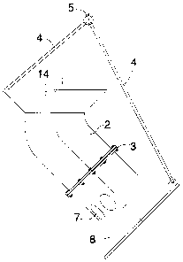
Figure 1 shows the equipment according to the
invention, directed downwards.
Figure 2 shows the equipment directed to the
side.
Figure 3 shows a partial longitudinal section of
the equipment of figure 1.
Figure 4 shows the equipment of figure 1 seen
2p from above.
The equipment shown in the drawing comprises a
set or a battery of hydraulic accumulators 1, in the
example according to the drawing seven accumulators,
which are held together by an enveloping jacket
structure 2 which in the drawing is made of two parts
joined together by means of a flange joint 3. The
accumulators 1 can have an initial charge pressure of
up to about 280 bar, although lower pressures also are
possible, and can for the rest either be of
conventional structure with a so-called gas bladder or
membrane, or possibly be made in principle as has been
presented in the patent application 931405, so that
they at first deliver liquid only and in a later
stage, when the drive pressure of the accumulators has
fallen, a mixture of liquid and drive gas.
The equipment is intended to by means of stays 4

WO 94125111 PCT/FI94/00172
3
and a lift loop 5 be able to be lifted and lowered as
needed from e.g. a helicopter or a crane.
The upper part of the jacket structure 2 in
figure 1 has a funnel-like part 6 widening upwards,
preferably more or less comically, and the lower part
of the jacket structure preferably has a number of
jacket openings 7 near the outlet nozzle heads of the
hydraulic accumulators 1, and a funnel-like part 8.
The outlet nozzle heads of the hydraulic
accumulators 1, which also can be called spray heads,
are visible in figure 3 and are designated 9. The
spray heads 9 are preferably made as presented in the
international patent application PCT/FI92/0155, with a
number of obliquely downwards and outwards directed
nozzles adapted mutually with respect to, among other
things, droplet size and accumulator drive pressure,
that they, producing a suction, deliver fog-like,
proportionally concentrated liquid sprays, which
effectively are capable of penetrating fire seats.
The hydraulic accumulators 1 are carried by a
support plate 10 visible in figure 3 and preferably
fixed in the lower part of the jacket structure 2 and
comprising a number of openings 11 visible in figure
4. Mutually between the hydraulic accumulators 1, as
well as between the hydraulic accumulators 1 and the
jacket structure 2, run air passages which are
designated 12 and are visible likewise in figure 4.
Reference numeral 13 in figure 13 indicates a band
element which under the influence of the flange joint
3 presses the hydraulic accumulators in abutment
against each other.
The equipment according to the invention can,
preferably from a helicopter, be lowered to a suitable
height above a fire seat and can be released by means
of remote controlled means, known per se and not shown
in the drawing. The nozzle heads 9 of the hydraulic

WO 94125111 PCTIFI94100172
~~60893 ..
4
accumulators produce a forceful suction, whereby
necessary additional air is sucked in partly through
the jacket openings 7 and partly via thev:.channels 12
running along the set of accumulators and out past the
nozzle heads 9 through the openings 11 of the plate
10. In particular through the jacket openings 7 will
also smoke gases be sucked in, which is of advantage
in that also these gases have an extinguishing effect.
As a fire can be attacked from above, which is
the case e.g. for forest fires, and the equipment thus
is in vertical position according to figures 1, 3 and
4, the air stream produced by the main rotor of the
helicopter, which air stream is partly collected by
the funnel-like part 6, boosts the penetration and the
general effect of the extinguishing liquid.
If it for some reason is not suitable to attack a
fire from above, the equipment can be turned obliquely
to the side, as shown in figure 3, possibly sideways
altogether. Such fires can be oil fires e.g. on oil
drilling rigs, or possibly fires in high buildings. At
least in certain such cases a crane or the like can be
used instead of a helicopter.
Especially in such cases, when the equipment is
turned sideways but it still is of advantage to carry
out the maneuvres of the equipment from a helicopter,
the air stream produced by the rotor of the helicopter
can be utilized by means of a bent-up funnel-like part
14 at the closed end of the long bottle-like hydraulic
accumulators 1, as is shown in figure 3. In the
embodiment of figure 3 there are no jacket openings 7
on the upper side of the jacket structure.

Representative Drawing
A single figure which represents the drawing illustrating the invention.
Administrative Status

2024-08-01:As part of the Next Generation Patents (NGP) transition, the Canadian Patents Database (CPD) now contains a more detailed Event History, which replicates the Event Log of our new back-office solution.

Please note that "Inactive:" events refers to events no longer in use in our new back-office solution.

For a clearer understanding of the status of the application/patent presented on this page, the site Disclaimer , as well as the definitions for Patent , Event History , Maintenance Fee  and Payment History  should be consulted.

Event History

Description Date
Time Limit for Reversal Expired 2010-05-04
Letter Sent 2009-05-04
Grant by Issuance 2005-09-20
Inactive: Cover page published 2005-09-19
Inactive: Final fee received 2005-07-06
Pre-grant 2005-07-06
Notice of Allowance is Issued 2005-05-09
Letter Sent 2005-05-09
Notice of Allowance is Issued 2005-05-09
Inactive: Approved for allowance (AFA) 2005-03-31
Amendment Received - Voluntary Amendment 2004-12-23
Inactive: S.30(2) Rules - Examiner requisition 2004-07-08
Letter Sent 2001-11-05
Letter Sent 2001-04-26
Inactive: Status info is complete as of Log entry date 2001-04-26
Inactive: Application prosecuted on TS as of Log entry date 2001-04-26
Inactive: Entity size changed 2001-04-25
Amendment Received - Voluntary Amendment 2001-04-04
Request for Examination Requirements Determined Compliant 2001-04-04
All Requirements for Examination Determined Compliant 2001-04-04
Deemed Abandoned - Failure to Respond to Maintenance Fee Notice 1997-05-05
Inactive: Adhoc Request Documented 1997-05-05
Application Published (Open to Public Inspection) 1994-11-10

Abandonment History

Abandonment Date Reason Reinstatement Date
1997-05-05

Maintenance Fee

The last payment was received on 2005-04-11

Note : If the full payment has not been received on or before the date indicated, a further fee may be required which may be one of the following

  • the reinstatement fee;
  • the late payment fee; or
  • additional fee to reverse deemed expiry.

Patent fees are adjusted on the 1st of January every year. The amounts above are the current amounts if received by December 31 of the current year.
Please refer to the CIPO Patent Fees web page to see all current fee amounts.

Fee History

Fee Type Anniversary Year Due Date Paid Date
MF (application, 4th anniv.) - small 04 1998-05-04 1998-04-22
MF (application, 5th anniv.) - small 05 1999-05-04 1999-04-14
MF (application, 6th anniv.) - small 06 2000-05-04 2000-04-17
Request for examination - standard 2001-04-04
MF (application, 7th anniv.) - small 07 2001-05-04 2001-04-12
MF (application, 8th anniv.) - standard 08 2002-05-06 2002-04-15
MF (application, 9th anniv.) - standard 09 2003-05-05 2003-04-15
MF (application, 10th anniv.) - standard 10 2004-05-04 2004-04-15
MF (application, 11th anniv.) - standard 11 2005-05-04 2005-04-11
Final fee - standard 2005-07-06
MF (patent, 12th anniv.) - standard 2006-05-04 2006-04-18
MF (patent, 13th anniv.) - standard 2007-05-04 2007-04-16
MF (patent, 14th anniv.) - standard 2008-05-05 2008-04-25
Owners on Record

Note: Records showing the ownership history in alphabetical order.

Current Owners on Record
MARIOFF CORPORATION OY
Past Owners on Record
GORAN SUNDHOLM
Past Owners that do not appear in the "Owners on Record" listing will appear in other documentation within the application.
Documents

To view selected files, please enter reCAPTCHA code :


To view images, click a link in the Document Description column. To download the documents, select one or more checkboxes in the first column and then click the "Download Selected in PDF format (Zip Archive)" or the "Download Selected as Single PDF" button.

List of published and non-published patent-specific documents on the CPD .

If you have any difficulty accessing content, you can call the Client Service Centre at 1-866-997-1936 or send them an e-mail at CIPO Client Service Centre.


Document
Description 
Date
(yyyy-mm-dd) 
Number of pages   Size of Image (KB) 
Representative drawing 1998-06-29 1 6
Abstract 1994-11-09 1 40
Description 1994-11-09 4 162
Claims 1994-11-09 2 59
Drawings 1994-11-09 3 38
Abstract 2004-12-22 1 16
Claims 2004-12-22 2 65
Representative drawing 2005-03-30 1 6
Reminder - Request for Examination 2001-01-07 1 119
Acknowledgement of Request for Examination 2001-04-25 1 178
Commissioner's Notice - Application Found Allowable 2005-05-08 1 161
Maintenance Fee Notice 2009-06-14 1 171
PCT 1995-10-17 9 379
Correspondence 2005-07-05 1 29
Fees 1997-04-15 1 35
Fees 1996-04-22 1 58