Language selection

Search

Patent 2160932 Summary

Third-party information liability

Some of the information on this Web page has been provided by external sources. The Government of Canada is not responsible for the accuracy, reliability or currency of the information supplied by external sources. Users wishing to rely upon this information should consult directly with the source of the information. Content provided by external sources is not subject to official languages, privacy and accessibility requirements.

Claims and Abstract availability

Any discrepancies in the text and image of the Claims and Abstract are due to differing posting times. Text of the Claims and Abstract are posted:

  • At the time the application is open to public inspection;
  • At the time of issue of the patent (grant).
(12) Patent: (11) CA 2160932
(54) English Title: GOLF TEE
(54) French Title: TEE POUR BALLE DU GOLF
Status: Term Expired - Post Grant Beyond Limit
Bibliographic Data
Abstracts

English Abstract

This invention is a new golf tee device to produce a straight trajectory for the driving of a golf ball from the tee area by means of an elevated, angled tube.


French Abstract

Cette invention est un nouveau dispositif de tee pour balle du golf destiné à produire une trajectoire rectiligne pour l'entraînement d'une balle de golf de la région de té au moyen d'un tube coudé élevé.

Claims

Note: Claims are shown in the official language in which they were submitted.

CLAIMS
I claim:
1. A golf tee which is comprised of:
(a) a hollow tube 75mm long, having one open end and a second spherically
closed
end with an inside diameter wide enough to allow insertion of a standard golf
ball
with 1mm clearance around its circumference;
(b) a cylindrical tapered post which is 55mm in length, having a point on one
end and
a diameter of 12mm at the second end, the second end attached to said tube at
an
angle so that when said post is inserted pointed end in ground vertically, the
open
end of the tube is higher above the ground than the closed end, allowing the
tube
to rest at an angle of 22° from the horizontal,
whereby the face of a golf club, striking the spherically closed end of the
tube, will cause a
golf ball inside said tube to be propelled out of the open end upward and
forward in a
straight trajectory.
2. The tee from claim 1, having a disk attached to the post 24mm from the
point of the post
to keep the closed end of the tube from making contact with the ground.
3. The tee from claims 1 and 2, whereby the second end of the post is attached
to the tube at
a point 55mm from the open end of the tube and centre line of post.
4. The tee from claims 1 to 3, whereby the tube wall thickness is 1mm.
5. The tee from claims 1 to 4, whereby the tube is made from high impact-
resistant plastic.
6. The tee from claims 1 to 5, whereby the disk has a diameter of 40mm and a
thickness of
2mm to distribute the load of the tube with a golf ball inside it.
5

Description

Note: Descriptions are shown in the official language in which they were submitted.


CA 02160932 1999-10-19
SPECIFICATION
This invention relates to the game of golf. The specific area is the start of
a hole where a
wooden or metal-wood club is used for the driving of a golf ball resting on an
elevated tee
device.
2. There are approximately 28 million golfers in North America and about 80%
of them
(myself included) have trouble properly hitting a golf ball resting on a
standard tee. The
main problem is that the club face puts unwanted side spin on said ball
causing said ball to
land in undesirable areas on either side of the safe fairway. This leads to
higher scores
which mean disappointment and/or frustration.
My golf tee solves the problem of unwanted side spin thusly:
(a) A golf ball is placed into the upper, open end of the tube and falls by
gravity to the
lower, closed end of the tube.
(b) The closed end of the tube, where the driving club face makes contact
through the
swing, shields the golf ball from direct contact with the club face.
(c) The length of the tube causes the golf ball to be propelled in a virtually
straight
trajectory, similar to a bullet fired inside a gun barrel, thereby allowing
said ball to
land on the safe fairway a good distance from the tee area.
(d) The disk provides weight distribution and an optimum height for striking
the tube
with a golf club.
2

CA 02160932 1999-10-19
BRIEF DESCRIPTION OF THE DRAWINGS
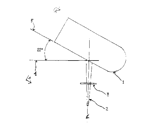
Figure 1 is a side elevation view of the present invention.
Figure 2 is a front view of the present invention.

CA 02160932 1999-10-19
DETAILED DESCRIPTION OF THE DRAWINGS
A tube 1, 75mm in length with an inside diameter of 46mm and wall thickness of
lmm, which has
an open end and a spherically closed end.
A post 2, SSmm in length which has a thickness of l2mm at the top end tapering
to a point at the
other end, said pointed end to insert vertically into the ground.
A disk 3, having a diameter of 40mm and a thickness of 2mm.
The horizontal plane 4.
An elevated plane 5 which rises 22° from the centre line of the post 2
and the horizontal plane 4.
The tube 1 is attached to the top end of the post 2 at an angle of 22°
from the horizontal plane 4
and at a point SSmm from the open, higher elevated, end of the tube and the
centre line of the
post.
The disk 3 is attached to the post 2 at a point 24mm from the pointed end of
the post and on the
centre line of the post and the centre point of the disk and parallel to the
horizontal plane 4.
4

Representative Drawing
A single figure which represents the drawing illustrating the invention.
Administrative Status

2024-08-01:As part of the Next Generation Patents (NGP) transition, the Canadian Patents Database (CPD) now contains a more detailed Event History, which replicates the Event Log of our new back-office solution.

Please note that "Inactive:" events refers to events no longer in use in our new back-office solution.

For a clearer understanding of the status of the application/patent presented on this page, the site Disclaimer , as well as the definitions for Patent , Event History , Maintenance Fee  and Payment History  should be consulted.

Event History

Description Date
Inactive: Expired (new Act pat) 2015-10-19
Inactive: IPC deactivated 2015-03-14
Inactive: IPC from PCS 2015-01-17
Inactive: First IPC from PCS 2015-01-17
Inactive: IPC from PCS 2015-01-17
Inactive: IPC expired 2015-01-01
Maintenance Request Received 2014-09-24
Maintenance Request Received 2013-09-25
Inactive: Office letter 2004-09-28
Change of Address Requirements Determined Compliant 2004-09-28
Change of Address or Method of Correspondence Request Received 2004-09-09
Grant by Issuance 2000-02-15
Inactive: Cover page published 2000-02-14
Pre-grant 1999-11-24
Inactive: Final fee received 1999-11-24
Publish Open to Licence Request 1999-11-24
Small Entity Declaration Determined Compliant 1999-11-24
Letter Sent 1999-11-17
Notice of Allowance is Issued 1999-11-17
Inactive: Approved for allowance (AFA) 1999-11-01
Amendment Received - Voluntary Amendment 1999-10-19
Inactive: S.30(2) Rules - Examiner requisition 1999-09-23
Inactive: Status info is complete as of Log entry date 1999-09-15
Inactive: Application prosecuted on TS as of Log entry date 1999-09-15
Amendment Received - Voluntary Amendment 1999-08-25
Application Published (Open to Public Inspection) 1997-04-20
Request for Examination Requirements Determined Compliant 1995-10-19
All Requirements for Examination Determined Compliant 1995-10-19

Abandonment History

There is no abandonment history.

Maintenance Fee

The last payment was received on 1999-09-28

Note : If the full payment has not been received on or before the date indicated, a further fee may be required which may be one of the following

  • the reinstatement fee;
  • the late payment fee; or
  • additional fee to reverse deemed expiry.

Patent fees are adjusted on the 1st of January every year. The amounts above are the current amounts if received by December 31 of the current year.
Please refer to the CIPO Patent Fees web page to see all current fee amounts.

Fee History

Fee Type Anniversary Year Due Date Paid Date
MF (application, 2nd anniv.) - small 02 1997-10-20 1997-10-10
MF (application, 3rd anniv.) - small 03 1998-10-19 1998-09-30
MF (application, 4th anniv.) - small 04 1999-10-19 1999-09-28
Final fee - small 1999-11-24
MF (patent, 5th anniv.) - small 2000-10-19 2000-10-16
MF (patent, 6th anniv.) - small 2001-10-19 2001-09-27
MF (patent, 7th anniv.) - small 2002-10-21 2002-10-02
MF (patent, 8th anniv.) - small 2003-10-20 2003-09-10
MF (patent, 9th anniv.) - small 2004-10-19 2004-09-09
MF (patent, 10th anniv.) - small 2005-10-19 2005-09-30
MF (patent, 11th anniv.) - small 2006-10-19 2006-09-07
MF (patent, 12th anniv.) - small 2007-10-19 2007-09-21
MF (patent, 13th anniv.) - small 2008-10-20 2008-10-03
MF (patent, 14th anniv.) - small 2009-10-19 2009-09-21
MF (patent, 15th anniv.) - small 2010-10-19 2010-09-14
MF (patent, 16th anniv.) - small 2011-10-19 2011-09-23
MF (patent, 17th anniv.) - small 2012-10-19 2012-09-07
MF (patent, 18th anniv.) - small 2013-10-21 2013-09-25
MF (patent, 19th anniv.) - small 2014-10-20 2014-09-24
Owners on Record

Note: Records showing the ownership history in alphabetical order.

Current Owners on Record
MICHAEL J. BAXTER
Past Owners on Record
None
Past Owners that do not appear in the "Owners on Record" listing will appear in other documentation within the application.
Documents

To view selected files, please enter reCAPTCHA code :


To view images, click a link in the Document Description column. To download the documents, select one or more checkboxes in the first column and then click the "Download Selected in PDF format (Zip Archive)" or the "Download Selected as Single PDF" button.

List of published and non-published patent-specific documents on the CPD .

If you have any difficulty accessing content, you can call the Client Service Centre at 1-866-997-1936 or send them an e-mail at CIPO Client Service Centre.


Document
Description 
Date
(yyyy-mm-dd) 
Number of pages   Size of Image (KB) 
Abstract 1999-10-18 1 7
Description 1999-10-18 3 64
Claims 1999-10-18 1 37
Drawings 1999-10-18 1 16
Description 1996-03-07 3 62
Abstract 1996-03-07 1 8
Claims 1996-03-07 1 24
Drawings 1996-03-07 1 17
Abstract 1999-07-28 1 8
Description 1999-07-28 2 46
Claims 1999-07-28 1 24
Abstract 1999-08-24 1 8
Description 1999-08-24 2 48
Claims 1999-08-24 1 37
Drawings 1999-08-24 1 15
Representative drawing 1997-07-09 1 5
Representative drawing 2000-01-23 1 5
Reminder of maintenance fee due 1997-06-21 1 109
Notice: Maintenance Fee Reminder 1997-07-21 1 119
Notice: Maintenance Fee Reminder 1998-07-20 1 131
Notice: Maintenance Fee Reminder 1999-07-19 1 120
Commissioner's Notice - Application Found Allowable 1999-11-16 1 164
Notice: Maintenance Fee Reminder 2000-07-19 1 118
Notice: Maintenance Fee Reminder 2001-07-22 1 120
Notice: Maintenance Fee Reminder 2002-07-21 1 130
Notice: Maintenance Fee Reminder 2003-07-21 1 115
Notice: Maintenance Fee Reminder 2004-07-19 1 119
Notice: Maintenance Fee Reminder 2005-07-19 1 117
Notice: Maintenance Fee Reminder 2006-07-19 1 119
Notice: Maintenance Fee Reminder 2007-07-22 1 121
Notice: Maintenance Fee Reminder 2008-07-21 1 122
Notice: Maintenance Fee Reminder 2009-07-20 1 118
Notice: Maintenance Fee Reminder 2010-07-19 1 123
Notice: Maintenance Fee Reminder 2011-07-19 1 121
Notice: Maintenance Fee Reminder 2012-07-22 1 128
Notice: Maintenance Fee Reminder 2013-07-21 1 120
Notice: Maintenance Fee Reminder 2014-07-21 1 120
Fees 2003-09-09 2 70
Correspondence 1995-11-16 6 207
Correspondence 1999-11-23 1 36
Fees 1998-09-29 1 72
Fees 2000-10-15 1 48
Fees 2001-09-26 2 79
Fees 2002-10-01 2 69
Fees 1997-10-09 1 67
Fees 1999-09-27 2 95
Correspondence 2004-09-08 3 142
Fees 2004-09-08 1 102
Correspondence 2004-09-27 1 7
Fees 2005-09-29 2 154
Fees 2006-09-06 2 115
Fees 2007-09-20 2 95
Fees 2008-10-02 2 279
Fees 2009-09-20 2 246
Fees 2010-09-13 1 133
Fees 2011-09-22 1 128
Fees 2012-09-06 2 258
Fees 2013-09-24 1 129
Fees 2014-09-23 1 123